Note: Descriptions are shown in the official language in which they were submitted.
2139459
PATENT APPLICATION
ATTORNEY DOCKET NUMBER D/93125
DRUM SUPPORTING HUB AND DRUM ASSEMBLY
BACKGROUND OF THE INVENTION
This invention relates in general to drum support apparatus and more
specifically to a drum supporting hub, a drum assembly containing the hub
and method for fabricating the drum assembly.
A photoreceptor conventionally utilized for copiers and printers
comprises a hollow electrically conductive cylindrical drum substrate which
has been dip coated with various coatings including at least one
photoconductive coating comprising pigment particles dispersed in a film-
forming binder. These drum type photoreceptors are supported on an
electrically conductive shaft by drum supporting hubs. The hubs are usually
constructed of plastic material and have a hole through their center into
which a supporting axle shaft is inserted. Since hubs are usually constructed
of electrically insulating plastic material, an electrical grounding means
comprising a flexible spring steel metal strip is secured to the hub and
positioned to contact both the electrically conductive axle shaft and the
electrically conductive metal substrate of the photoreceptor drum. One
type of grounding means is illustrated in US-A 4,561,763. This metal
ground strip is often bent out of alignment when inserted into one end of a
photoreceptor drum. Such misalignment can result in the metal strip not
contacting the interior of the drum or the axle or both after insertion of the
hub into the end of the drum is completed. Further, coatings electrically
insulating in the dark that are formed on the surface of the interior of the
drum during dip coating can adversely affect electrical grounding of the
drum to the electrically conductive drum axle shaft. If inadequate electrical
grounding of the drum to the axle shaft is detected after the drum has
been inserted into a modular replacement unit in which photoreceptor and
various other subsystems such as cleaning and charging units are
permanently mounted, repair of the drum is usually impossible without
1
2139459
destruction of the module. Often the hub is secured to the end of the drum
by a thermosetting resin. Recycling of used drums having glued hubs is
difficult, if not impossible, because of damage to the hub or the drum or
both during removal of the hub from the drum by common techniques such
as by hammering. Such removal techniques damage or destroy both the
drum and the hub. The use of bolts and nuts to secure hubs to drums
requires time intensive activity and does not address the problem of
electrically grounding a drum substrate to the drum axle shaft.
Thus, there is a continuing need for improved photoreceptors that are
more reliable and facilitate recycling.
INFORMATION DISCLOSURE STATEMENT
US-A 4,561,763 to D. Basch issued on December 31, 1985 a drum
supporting hub is disclosed having a tapered pot-like hub configuration
comprising a bottom section and a rim, the rim comprising a plurality of
circumferentially spaced resilient fingers extending at a slight incline
outwardly from the axis of the pot-like hub away from the bottom section,
at least three of the fingers having lips at the ends of the fingers, the lips
projecting away from the axis for engagement with an end of a cylindrical
drum upon insertion of the pot-like hub into the drum, the rim other than
the lips having an outside diameter slightly larger than the outside
diameter of the bottom. The drum supporting hub is employed in a drum
assembly comprising the hub, a cylindrical drum having a circular cross-
section and a shaft positioned along the axis of the drum. A metal shim is
utilized to electrically ground the drum to the shaft.
SUMMARY OF THE INVENTION
It is, therefore, an object of the present invention to provide an
improved drum supporting hub and drum assembly which overcomes the
above-noted disadvantages.
It is another object of this invention to provide an improved drum
supporting hub and drum assembly which achieve excellent electrical
2
grounding of an electrostatographic substrate which does not degrade over
time.
It is still another object of this invention to provide an improved drum
supporting hub and drum assembly which facilitate recycling of
electrostatographic
drums and hubs.
It is yet another object of this invention to provide an improved drum
supporting hub and drum assembly which reduces the number of assembly steps
utilized to manufacture an electrostatographic drum.
It is another object of this invention to provide an improved drum supporting
hub and drum assembly which eliminates the need for gluing to mount a hub to
the
end of an electrostatographic drum.
It is another object of this invention to provide an improved drum supporting
hub and drum assembly which quickly achieves excellent anchoring of the hub to
the
drum.
In accordance with another aspect of the present invention is a drum
supporting hub comprising a disk shaped member having a circular periphery, a
hole extending axially through the center of said disk shaped member, and at
least
one long thing electrically conductive resilient member secured to said disk
shaped
member, said resilient member having a central section adjacent said hole and
having opposite ends, each of said ends terminating into at least one pointed
tip
adjacent said circular periphery of said disk shaped member for engagement
with a
cylindrical drum upon insertion of said hub into said drum, and said resilient
member having a major plane substantially parallel to the axis of said disk
shaped
member.
According to another aspect of the present invention is an electrostatographic
imaging member assembly comprising a hollow cylindrical electrically
conductive
substrate having an interior surface and a coated outer surface and a drum
supporting hub mounted on at least one end of said conductive substrate, said
hub
comprising a disk shaped member having a circular periphery, a hole extending
axially through the center of said disk shaped member, and at least one long
thin
electrically conductive resilient member secured to said disk shaped member,
said
resilient member having a central region adjacent said hole and having
opposite ends
3
2~ 38459
bent in opposite directions from each other, and each of said ends terminating
into at
least one pointed tip embedded into said interior surface of said substrate.
In accordance with yet another aspect of the present invention is a process
for fabricating an electrostatographic imaging member assembly comprising
providing a hollow cylindrically shaped electrostatographic imaging member
having
an interior surface, a coated outer surface and two ends, providing a drum
supporting a hub comprising a disk shaped member having a circular periphery,
a
hole extending axially through the center of said disk shaped member, and at
least
one long thin electrically conductive resilient member secured to said disk
shaped
member, said resilient member having a central region adjacent said hole and
having
opposite ends, each end of said resilient member terminating into at least one
pointed tip adjacent said circular periphery of said disk shaped member, and
inserting said hub with a twisting motion into one of said ends of said hollow
cylindrically shaped electrostatographic imaging member to bend said
electrically
conductive resilient member whereby said pointed tip at each end of said
resilient
member engages said interior surface to retain said hub in an end of said
hollow
cylindrically shaped electrostatographic imaging member.
The foregoing and other objects of the present invention are accomplished by
providing a drum supporting hub comprising a disk shaped member having a
circular periphery, a hole extending axially through the center of the disk
shaped
member, and at least one long thin electrically conductive resilient member
secured
to the disk shaped member, the resilient member having a central section
adjacent
the hole and having opposite ends, each of the ends terminating into at least
one
pointed tip adjacent the circular periphery of the disk shaped member, and the
resilient member having a major plane substantially parallel to the axis of
the disk
shaped member. This hub may be inserted in at least one end of a cylindrical
electrostatographic imaging member to produce an imaging member assembly.
BRIEF DESCRIPTION OF THE DRAWINGS
In general, the advantages of the improved drum supporting hub and drum
assembly will become apparent upon consideration of the following disclosure
of the
invention, particularly when taken in conjunction with the accompanying
drawings
wherein:
3a
"p.
2139459
FIG. 1 is a schematic illustration of a long thin substantially flat
electrically conductive resilient member utilized in the drum supporting
hub of this invention.
FIG. 2 is a schematic illustration of the resilient member illustrated in
FIG. 1 viewed from one side.
FIG. 3 is a cross section of the resilient member viewed in the direction
illustrated by the arrows in FIG. 2.
FIG. 4 is a drum supporting hub of this invention utilizing a pair of
resilient members.
FIG. 5 is a schematic illustration of the drum supporting hub illustrated
in FIG. 4 viewed from one side.
FIG. 6 is a schematic illustration of the drum supporting hub illustrated
in FIG. 4 mounted in one end of an electrostatographic imaging member.
FIG. 7 is another embodiment of a drum supporting hub of this
invention in which a pair of resilient members are supported by a bearing
component of the drum supporting hub.
FIG. 8 is a schematic illustration of the drum supporting hub illustrated
in FIG. 7 viewed from one side.
FIG. 9 is another embodiment of a drum supporting hub of this
invention.
FIG. 10 is still another embodiment of a resilient member of this
invention
FIG. 11 is an illustration of another embodiment of a resilient member
of this invention.
FIG. 12 is schematic, illustration of still another embodiment of a drum
supporting hub of this invention.
These figures merely schematically illustrate the invention and are not
intended to indicate relative size and dimensions of actual devices
components thereof.
DETAILED DESCRIPTION OF THE DRAWINGS
The present invention may be employed in any suitable device that
requires support for a drum. However, for purposes of illustration, the
4
21 394 59
invention will be described with reference to an electrostatographic
imaging system. A typical electrophotographic imaging system is
illustrated in U.S. Patent No. 3,900,258 to R.F. Hoppner et al.
Referring to FIGS. 1 and 2, a long thin substantially flat electrically
conductive resilient member 10 is illustrated having opposite ends which
terminate into at least one pointed tip 12. The ends of the resilient
member 10 should have at least one pointed tip 12 to achieve embedding
of the end of the resilient member into the interior surface of hollow
cylindrical electrically conductive substrates (not shown) into the interior
of
which resilient member 10 is inserted. Resilient member 10 should be
tapered at each end with the taper terminating in at least one point 12.
The amount of taper does not appear critical but is desirable to facilitate
insertion of the resilient member into the interior of the substrate when
the drum supporting hub is inserted by a twisting motion. A taper may be
used on both sides of tip 12 or on only one side, the other side being
straight (not shown). Tip 12 and adjacent end region 18 of resilient
member 10 are shown bent in opposite directions from each other in FIG. 2.
Resilient member 10 has a central section 16, the center region 17 of which
contains at least one flared edge 14. Any suitable material may be utilized
for long thin substantially flat electrically conductive resilient member 10.
Resilient member 10 should also be bendable, but resist permanent
deformation. Preferably, resilient member 10 comprises a metal having
hard, spring-like properties. Typical hard, spring-like metals include, for
example, stainless steel, copper beryllium alloy, phosphorous bronze and
the like or a conductive plastic. Resilient member 10 should have an
electrical resistivity of less than about 1000 ohm cm. The specific material
and length, width, and thickness selected affect the resiliency of resilient
member 10. The Width and thickness should be sufficient to resist
permanent deformation and to retain the drum supporting hub (not
shown) in position at at least one end of the hollow cylindrical drum.
Typical physical widths are, for example, between about 0.2 centimeter and
~'~ 3g4~9~
about 1 centimeter and typical thicknesses are between about 0.25
millimeter and about 1 millimeter.
In FIG.3, a cross section of resilient member 10 is shown taken in the
direction shown by the arrows illustrated in FIG. 2.
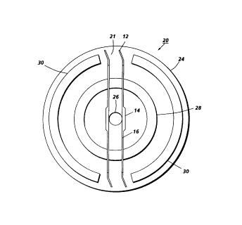
In FIG. 4, a drum supporting hub 20 is shown which comprises disk
shaped member 21 to which is attached optional drive gear 22 having gear
teeth 23 arranged around the periphery thereof. If desired, disk shaped
member 21 and drive gear 22 may be formed as a unitary article by any
suitable technique such as molding. Gear teeth 23 are adapted to engage
with the teeth of another gear (not shown) connected to a suitable power
source as is conventional in the art. Such an arrangement is well known in
the art and is illustrated, for example, in U.S. Patent 3,900,258 to R.F.
Hoppner et al.
Alternatively, hub 20 may be driven directly by hexagonal or square axle
shafts (not shown) which mate with correspondingly shaped openings in
hub 20. The axle shaft can be driven directly by an electric motor (not
shown) or by any other suitable power source as is well known in the art.
Disk shaped member 21 has a circular periphery 24 and a centered hole 26.
A circular rib or ridge 28 is formed as an integral part of the molded disk
shaped member 21 by conventional processes such as molding. If desired,
circular ridge 28 can be preformed and thereafter fastened to disk shaped
member 21 by any suitable means such as by an adhesive, screw or the like.
Circular ridge 28 secures a pair of spaced, parallel resilient elements 10 to
disk shaped member 21 adjacent to hole 26. Disk shaped member 21
utilized in drum supporting hub 20 may be made of any suitable material
such as plastic or metal. Typical plastic materials include thermosetting or
thermoplastic resins which are dimensionally stable. These plastic members
may be filled or unfilled. Any suitable conventional filling material may be
utilized. Typical thermoplastic resins include, for example, acrilonitrile
butadiene styrenes (ABS), polycarbonates, nylons, acrylics and the like.
Typical thermosetting resins include, for example, alkyds, allylics, epoxies,
phenolics, and the like. Although more expensive, metals such as steel,
6
jfp
"QR........;orv
21.39459
aluminum, copper, bronze, brass and the like may be utilized in disk
shaped member 21.
Although resilient member 10 is shown secured to hub 20 by ridge 28
into which resilient member 10 is molded, it may be secured to disk shaped
member 21 by any other suitable means. For example, resilient member 10
may be bolted or otherwise screwed to ridge 28 or other suitable
projections extending toward the interior of a hollow cylindrical drum
supported by hub 20. If desired, ridge 28 may contain slots in which the
resilient member 10 is glued or secured by mechanical fastening means such
as screws, clamps or the like.
The central section 16 of resilient members 10 have a major plane
substantially parallel to the axis of hole 26. In other words, the larger
surface rather than the thin edge surfaces of resilient members 10 will come
into substantially tangential contact with the arcuate surface of the axle
shaft (not shown) that will eventually be used to support the hub 20. Since
resilient member 10 is substantially flat, the expression "major plane", as
employed herein, is defined as in the plane of either side of the central
section 16 of the large exposed surfaces of resilient member 10 rather than
in the plane of either of the narrow edge surfaces of thin resilient member
10. Resilient members 10 are aligned so that they interfere slightly with the
installation of an axle shaft (not shown) through hole 26 and bow slightly
(not shown) away from the axle shaft after it is inserted between resilient
members 10. This slight interference insures frictional and electrical contact
after the axle shaft has been inserted through hole 26 and through the
space between resilient members 10. Although a single long thin
substantially flat electrically resilient member 10 may be utilized, a second
resilient member 10 positioned on the other side of the axle shaft is
preferred to achieve a balanced load on the axle shaft and to ensure
electrical contact between the axle shaft and the interior of the hollow
cylindrical electrically conductive substrate. To facilitate insertion of an
axle shaft in the space between resilient members 10, flared edges 14 are
provided on each resilient member to initially engage the end an axle shaft
as it is inserted between resilient members 10. The flared edges 14 function
7
2.39459
as inclined planes to spread apart resilient members 10 and prevent
damage to resilient members 10 when the axle shaft is inserted. The
location of flared edge 14 depends on the direction in which the axle shaft
is inserted. Thus, if the axle shaft is initially inserted into hole 26 prior
to
passage through the space between resilient members 10, flared edges 14
are located on the side of resilient members 10 closest to disk shaped
member 21. However, if the axle shaft is initially inserted into the far end
of a drum prior to passage through the space between resilient members
10, flared edges 14 are located on the side of resilient members 10 facing
the far end of the drum. If the axle shaft might be inserted from either end
of the drum, it is desirable that a flared edge 14 be provided on both edges
of each resilient member 10.
Semi-circular drum alignment ridges 30 are also molded into disk
shaped member 21. If desired, alignment ridges 30 can be preformed and
thereafter fastened to disk shaped member 21 by any suitable means such
as by an adhesive, screw or the like. Drum alignment ridges 30 ensures that
drum supporting hub 20 is centered in the end of drum (not shown). If
desired, the side of drum alignment ridge 30 facing the interior surface of
the drum may be tapered, beveled or otherwise or inclined toward the
drum centerline (not shown) to facilitate insertion of hub 20 into one end
of the drum and to promote a snug fit between hub 20 and the drum.
Thus, for example, drum alignment ridges 30 may have a truncated cross
section. Alternatively, instead of using alignment ridges 30, a conventional
recess (not shown) may be formed in circular periphery 24 to accept the end
of a drum or a conventional recess (not shown) may be formed in the end of
a drum adjacent the interior surface of the drum to accept hub 20.
Prior to installation into the end of a drum, the pointed tips 12 of the
resilient members 10 extend beyond the outer edge of semi-circular drum
alignment ridge 30 as shown in FIGS. 4 and S. The amount that resilient
members 10 extend beyond the outer edge of semi-circular drum
alignment ridge 30 should be sufficient to achieve compression of resilient
member 10 and ensure positive engagement of pointed tips 12 with the
interior surface of a cylindrical drum upon insertion of hub 20 into one end
8
_139459
of the drum. Similarly, the opening between adjacent ends of alignment
ridge 30 should be sufficiently wide to permit adequate movement of the
resilient fingers 26 during insertion of the supporting hub 16 into the end
of cylindrical drum 12 {see FIG. 6). In a typical example, the pointed tip of
the resilient member extends about 1 millimeters (1/32) inch beyond the
outer edge of the drum alignment ridge 30. The width of the sides of
flared edge 14 should be sufficient to catch and guide axle shaft 40 when it
is inserted into the hole of the drum supporting hub 20. A landing 32 is
provided on the face of disk shaped member 21 to engage with and align
supporting hub 20 with the drum into which supporting hub 20 is inserted.
If desired, landing 32 may alternatively be formed as a recessed surface (not
shown) cut or molded into circular periphery 24.
Referring to FIG. 6, drum supporting hub 20 is shown after it has been
inserted into one end of an electrostatographic imaging drum 34.
Electrostatographic imaging drum 34 comprises a hollow cylindrical
electrically conductive substrate 36 and at least one electrostatographic
layer 38. Electrostatographic layers are well known in the art and may
comprise a dielectric layer for electrographic imaging or at least one
electrophotographic imaging layer for electrophotographic imaging. An
axle shaft 40 has been installed through hole 26 and in the space between
resilient members 10. Flared edges 14 facilitated insertion of axle shaft 40
between resilient members 10. Since the space between resilient members
prior to insertion of axle shaft 40 is less than the diameter of axle shaft
40, frictional engagement between axle shaft 40 and resilient members 10
is achieved. Frictional engagement ensures electrical contact. This
arrangement permits electrical grounding of drum 34 through resilient
member 10 and shaft axle shaft 40.
Drum supporting hub 20 is inserted into the end of drum 34 with a
twisting motion of either drum supporting hub 20 or drum 34, or both
drum supporting hub 20 and drum 34. Preferably, end regions 18 at each
end of resilient member 10 adjacent pointed tip 12 are bent at an angle of
up to about 60 degrees measured from the original plane of resilient
member 10 prior to bending to enhance the attack angle of pointed tip 12
9
_2~3945~
into the interior surface of drum 34. A typical angle of attack is 30°.
This
prevents slippage between hub 20 and drum 34 when hub 34 is driven by
any suitable means as drive gear 22. Preferably, the distance of the bend
from pointed tip 12 is between about 2 millimeters and about 25 percent of
the total length of resilient member 10. The direction of rotation for
driving is in a direction Which increases bite of the pointed tip into the
substrate. When drum 34 is stationary and hub 20 is inserted into the end of
drum 34 opposite the end closest to the viewer of FIG. 6, hub 20 is twisted in
a clockwise direction. If hub 20 is held stationary, drum 34 is moved in a
counter-clockwise direction when it is mounted onto hub 20. The twisting
motion causes the bent adjacent end region 18 to bend even more thereby
facilitating insertion of resilient members 10 into the interior of drum 34.
When drum 34 is rotated by drive means which engage gear teeth 23 of
drive gear 22, the direction of motion of hub 20 should be in the direction
indicated by arrow B. This causes pointed tips 12 to further embed
themselves into the interior surface of drum 34 to prevent slippage
between drum 34 and hub 20. Avoidance of slippage assures registration
of electrostatographic images and enhances achievement of quality
electrostatographic images.
When it is desired to remove hub 20 from the end of drum 34 and
drum 34 is to be held stationary, hub 20 should be twisted in the direction
illustrated by arrow A in FIG. 6. Since hub 20 may be readily removed from
drum 34 without damage to drum 34 or hub 20, both components may be
easily recycled with less waste of material and less expenditure of time.
In FIG. 7, another embodiment is illustrated in which drum supporting
hub 50 comprises an annular outer member 52 and a bearing member 54.
A pair of long thin substantially flat electrically conductive resilient
members 56 are molded into bearing member 54. Also molded into
bearing member 54 is an annular retainer ridge 58 and a key 60. If desired,
any other suitable means may be substituted for key 60 for securing
bearing member 54 to annular outer member 52. Typical alternative means
include, for example, collar in annular outer member 52 fitted with a set
screw (not shown). Bearing member 54 along With resilient members 56
2139459
can be readily mounted into annular outer member 52 by merely pressing
bearing member 54 into a hole 62 located at the center of annular outer
member 52 until retainer ridge 58 extends through to the opposite side of
annular member 52 thereby locking bearing member 54 into annular outer
member 52. If removal of bearing member 54 from annular outer member
52 is desirable at a later date, such removal may be readily facilitated by
means of an ordinary punch. Key 60 of bearing member 54 engages a
corresponding slot in hole 62 in annular outer member 52 to prevent
rotation of bearing member 54 in hole 62.
Still another embodiment of this invention is shown in FIG. 9 in which
drum supporting hub 70 comprises a plurality of separate drum alignment
projections arranged in a generally circular formation instead of a solid
ridge such as semi-circular drum alignment ridges 30 shown in FIG. 4. A
long thin substantially flat electrically conductive resilient member 76 is
secured to support hub 70 by means of support projections 78. Resilient
member 76 may be directly molded into the support projections 78 or
merely inserted and glued into slots formed in support projections 78. Any
other suitable means of mounting resilient member 76 to hub 70 may be
substituted for support projections 78, if desired.
- In FIG. 11, another embodiment of a long thin substantially flat
electrically conductive resilient member 80 is shown. Resilient member 80
comprises a centrally located flared edge 82 and pointed tip 84 at each end.
End region 86 adjacent to tip 84 is not bent and is in the same plane as most
of resilient member 80. At least one tapered side 88 leading to pointed tip
84 facilitates entry of resilient member 80 into the interior of the drum
when the drum supporting hub (not shown) is twisted into one end a drum
(not shown). If only one tapered side is utilized at each end of a resilient
member, the tapered side should face the end of the drum into which the
hub is inserted. The expression "tapered side" as employed herein is
intended to indicate an edge leading to a pointed tip, the edge being
inclined relative to the longitudinal centerline of a long thin substantially
flat electrically conductive resilient member.
11
--- X139459
In FIG. 11, another embodiment of a long thin substantially flat
electrically conductive resilient member 90 is shown with flared edges 92
and a plurality of pointed tips 94. Although only two pointed tips 94 at
each end of resilient member 90 are shown, three or more tips may be
utilized if desired.
FIG. 12 illustrates another drum supporting hub 100 of this invention.
Hub 100 comprises a disk shaped member 102 bearing arc shaped
alignment ridges 104 and a circular ridge 106 which supports a pair of long
thin substantially flat electrically conductive resilient members 180
arranged perpendicular to another pair of long thin substantially flat
electrically resilient members 112. Resilient members 108 and 112 straddle
hole 110 which is provided for an axle shaft (not shown) to increase the
surface area available for frictional engagement and electrical contact
between resilient members 108 and 112 the exterior surface of an axle shaft
and also to promote enhanced self centering of hub 20 and drum (not
shown) around the axle shaft. The space between each resilient member of
a pair should be slightly less than the diameter of the axle shaft to ensure
positive electrical contact with the axle shaft.
Although, the hubs illustrated in the drawings may be identical at
each end of the drum, the drum supporting hubs need not be identical.
The invention has been described in detail with particular reference to
preferred embodiments thereof but it will be understood that variations
and modifications can be effected within the spirit and scope of the
invention as described herein above and as defined in the appended claims.
12