Note: Descriptions are shown in the official language in which they were submitted.
~- 21~96~6
8TEERABLE CA,nh ~K
Field Of Invention
This invention relates to medical catheters,
and more particularly to steerable catheters for
inserting into body vessels or cavities.
Background Of The Invention
Various commercially available catheters and
endoscopes exist for introducing into the body vessels
and cavities a variety of surgical tools, fluids, and
other materials, such as radiographic contrast
materials, angioplasty balloons, fiberoptic scopes,
laser lights, and cutting instruments. Also, various
techniques and systems have been developed for guiding
or steering the catheters in the body vessels and
cavities for use of these tools, fluids, and other
materials.
Examples of such guiding or steering
techniques and systems for catheters may be seen in
U.S. Patent No. 4,983,165 to Loiterman entitled
"Guidance System For Vascular Catheter Or The Like,"
U.S. Patent No. 4,776,844 to Ueda entitled "Medical
Tube," U.S. Patent No. 4,934,340 to Ebling et al.
entitled "Device For Guiding Medical Catheters and
Scopes," U.S. Patent No. 4,930,521 to Metzger et al.
entitled "Variable Stiffness Esophageal Catheter," U.S.
Patent No. 3,470 to Barchilon entitled "Dirigible
Catheter," U.S. Patent No. 3,605,725 to Bentov entitled
"Controlled Motion Devices," and the Patent Cooperation
2i3~46
-2-
Treaty ("PCT") Patent Application No. PCTWO88/00810 of
Tenerz et al. entitled "Guide For Mechanical Guiding Of
A Catheter In Connection With Cardio And Vessel
Ex~m;n~tion. " These catheters, however, failed to give
the physician or other operator sufficient control of
the distal end of the catheter and made it difficult to
manipulate the distal end for specific isolation on
particular sections of the body vessel or cavity.
Some steerable catheters or systems have been
made to try to give the physician control of the use of
the catheter during surgical procedures wherein fluids
and the various tools are needed for the operation by
providing a flexible tube for controlling the direction
of movement of the distal end of the catheter.
Examples of these other attempts may be seen in the PCT
Patent Application No. PCTWO91/11213 of Lundquist et
al. entitled "Catheter Steering Mechanism," European
Patent Application No. 370,158 of Martin entitled
"Catheter For Prolonged Access," and U.S. Patent No.
4,737,142 to Heckele entitled "Instrument For
~min~tion And Treatment Of Bodily Passages." These
devices, however, still failed to provide the control
and manipulation of the catheter needed for use with
the surgical tools and fluids required for an
operation.
Other attempts to control and manipulate the
catheter, such as seen in U.S. Patent 4,986,258 by Cho
et al. entitled "Endoscope With Tapered Shaft" and
European Patent Office Published Application 0-489-937-
A1 by Schmitt et al. entitled "Medical Instrument",fail to provide adequate control and manipulation while
also providing adequate access to a lumen of the
catheter during the surgical procedures or the like.
Therefore, there is still a need for a
steerable catheter that provides the control and
manipulation of the catheter for simultaneous use with
the surgical tools, such as fiberoptic scopes or the
AMENI~EO SHEET
~1~9646
-2/1-
like, and fluids needed for medical operations to
thereby allow the physician to positionally locate and
isolate problem areas within the body vessel or cavity.
SummarY Of The Invention
It is therefore an object of the present
invention to provide a catheter having improved
steering.
~4MEND,E~) SHEET
.
~ 21~64~ :
It is also an object of the present invention
to provide a catheter that allows the physician or
operator to have more control over the distal end
therein and provides feedback to the physician of the
angular attitude of the distal end.
It is another object of the present invention
to provide a catheter having a housing of such a size
as to be readily held in the hand of the user for the
physician or operator to control the steering of the
catheter while simultaneously providing access to the
lumen within the catheter for various surgical tools or
fluids.
It is a further object of the present
invention to provide a catheter having a fiberoptic
scope sheath adapted to engage the housing of the
catheter for inserting a fiberoptic scope into a lumen
of the catheter.
These and other objects, features, and
advantages of the present invention are provided in a
catheter having more controlled movement in the distal
end and having feedback on this movement to the
catheter user the details of which are disclosed in the
detailed description and the enclosed drawings.
In accordance with the present invention, a
steerable catheter is provided for use in body vessels
or cavities. The steerable catheter comprises a
housing having upper and lower surfaces and being of
such a size as to be readily held in the hand of the
user. The catheter also has elongate tube means having
a proximal end connected to the housing and extending
outwardly therefrom and being formed of material of
such a stiffness so as to maintain the elongate tube
means in a substantially straight condition in the
absence of an external force applied thereto. A distal
end portion of the elongate tube means is flexible.
Guide wires are connected to the housing by the
proxl~l ends thereof and extend outwardly
~ lFNn~ S~lE~
4 2139~46 - -
therefrom through the elongate tube means. The distal
ends of the guide wires are connected to the flexible
distal end portion of the elongate tube means. Guide
wire control means is carried by the housing and
cooperates with the proximal end portions of the guide
wires for controlling the angular attitude of the
flexible distal end portion of the elongate tube means.
The guide wires and control means cooperate so as to
limit the angular attitude of the flexible distal end
portion of the elongate tube means to angular
adjustments in a common plane extending generally
parallel to the upper surface of the housing and
wherein the angular adjustment of the flexible distal
end portion of the elongate tube means in all other
planes is obtained by rotation of the user's hand, so
that more control of the attitude of the flexible
distal end portion of the elongate tube means is
obtained during use of the catheter.
A pair of lumen extend longitudinally from
the distal end of the elongate tube means and into the
housing. The housing has a pair of access ports
positioned in the upper surface of the housing which
provide access to the pair of lumen preferably through
a piping connector. A fiberoptic sheath is adapted to
be attached to the access port of the housing for
inserting a fiberoptic scope or the like through one of
the access ports and into one of the lumen. A proximal
tube is also provided which extends through the housing
and preferably outwardly from a pro~;m~l end of the
housing.
Brief DescriDtion Of The Drawin~s
FIG. 1 is an environmental view of the
steerable catheter being held by the hand of the
catheter operator while simultaneously having a
fiberoptic scope inserted into an access port in the
housing of the catheter according to a preferred
~-ho~;ment of the present invention.
AMEN~ED SHEET
213954~ - -
-4\1-
FIG. 2 is a top plan view of the steerable
catheter with the top cover removed from the housing
and with parts broken away for clarity.
AMEN~E~ SHEEl'
2i39646
FIG. 3 is a bottom plan view of the steerable
catheter with the bottom cover removed from the housing
and with parts broken away for clarity.
FIG. 4 is a side cross-sectional view of the
steerable catheter according to the preferred
embodiment of the present invention.
FIG. 5 is an exploded view of the control
wheel of the housing according to the preferred
embodiment of the present invention.
FIG. 6 is an enlarged view of the flexible
outer end portion of the elongate tube means of the
steerable catheter taken from the circled portion of
FIG. 4 and rotated ninety (go) degrees.
FIG. 7 is an enlarged front view of the
flexible outer end portion of the elongate tube means
of the steerable catheter taken along line 7-7 of FIG.
6.
FIG. 8 is a top plan view of the steerable
catheter with the top cover removed from the housing
and with the control wheel rotated so as to move the
flexible outer end portion of the elongate tube means
of the steerable catheter to the right.
FIG. 9 is a top plan view of the steerable
catheter with the top cover removed from the housing
and with the control wheel rotated so as to move the
flexible outer end portion of the steerable catheter to
the left.
FIG. 10 is a side view of the steerable
catheter having the fiberoptic scope sheath attached to
an access port in the housing according to a preferred
embodiment of the present invention.
FIG. 11 is an enlarged view of the circled
portion of the steerable catheter having the fiberoptic
scope sheath from FIG. 10 with parts broken away for
clarity.
21~964~
--6--
FIG. 12 is a cross-sectional view of the
steerable catheter with the fiberoptic scope sheath
taken along line 12-12 of FIG. 10 according to the
preferred embodiment of the present invention.
FIG. 13 is a top plan view of the steerable
catheter according to the present invention with the
top cover removed from the housing and with parts
broken away for clarity illustrating another embodiment
of the control means for the catheter.
FIG. 14 is a bottom plan view of the
steerable catheter according to the present invention
with the bottom cover removed from the housing and with
parts broken away for clarity illustrating another
embodiment of the control means for the catheter.
FIG. 15 is a side view of the steerable
catheter according to the present invention with parts
broken away for clarity illustrating another embodiment
of the control means for the catheter.
FIG. 16 is an exploded view of the control
wheel according to another embodiment of the present
invention .
FIG. 17 is an enlarged view of the flexible
outer end portion of the elongate tube means of the
steerable catheter according to another embodiment of
the present invention taken from the circle portion in
FIG. 15 and rotated ninety (90) degrees.
FIG. 18 is an enlarged front view of the
flexible outer end portion of the elongate tube means
of the steerable catheter according to another
embodiment of the present invention taken along line
18-18 of FIG. 17.
FIG. 19 is a top view with the top cover of
the housing removed therefrom according to another
embodiment of the present invention and illustrating
the movement to the flexible outer end portion of the
elongate tube means of the steerable catheter.
213964~
FIG. 20 is a top view with the top cover of
the handle member removed therefrom according to
another embodiment of the present invention and
illustrating the movement to the flexible outer end
portion of the elongate tube means of the steerable
catheter.
Descript~on Of A Preferre~ Embo~iment
The present invention now will be described
more fully hereinafter with reference to the
accompanying drawings in which a preferred embodiment
of the invention is shown. Like numbers refer to like
elements throughout.
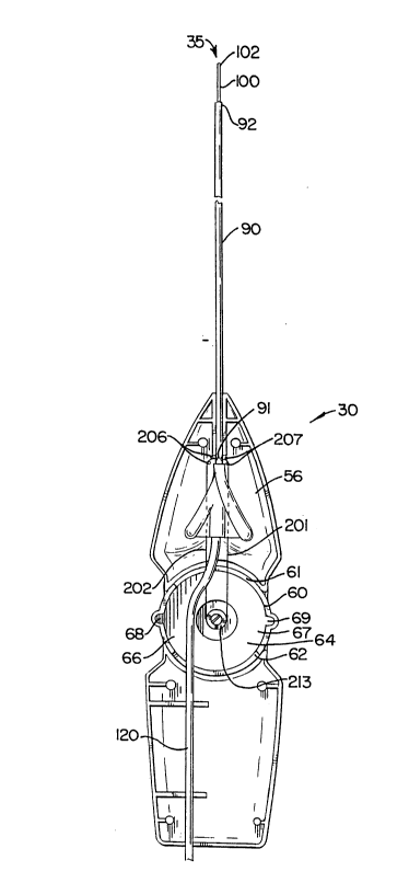
Referring now to FIG. 1, shown is an
environmental view of a preferred embodiment of the
steerable catheter 30 having distal 35 and proximal 45
ends according to the present invention. The steerable
catheter 30 is being held in the hands of a catheter
operator, such as a physician. The steerable catheter
30 has a housing 50, an elongate tube means 80, and a
proximal tube 120. The elongate tube means 80 has a
first tube and a second tube 100. Two lumens 94, 9S
(FIG. 7) extend longitudinally from the distal end 35
of the catheter, through the first 90 and second 100
tubes of the elongate tube means 80 and into the
housing 50. The first tube 90 is formed of a material
of such a stiffness so as to maintain the first tube 90
in a substantially straight condition in the absence of
an external force applied thereto. It is understood
that a substantially straight condition would generally
mean that the tube in not generally bendable but a
certain amount of arc may occur under some conditions
or application of an external force as previously
mentioned. The second tube 100 is generally more
flexible than the first tube 90. The elongate tube
means 80 in this embodiment comprises the first tube 90
2139546
.
-- --8--
and the second tube 100, but this invention would
include using one, two, or more tubes.
The housing 50 is of such a size as to be
readily held in the hand of the catheter operator or
other user. Access ports 161, 162 are provided in the
housing 50 for accessing the two lumens 94, 95 within
the elongate tube means 80. One end 91 of the first
tube 90 is connected to the housing 50 and then the
first tube 90 extends outwardly therefrom. The second
tube loo, in turn, extends longitudinally from a second
end 92 of the first tube 90. An end 102 of the second
tube 100 forms the distal end 35 of the steerable
catheter 30. The proximal tube 120 extends
longitudinally through the housing 50 and extends
lS longitudinally from the housing 50. A first end 121
(not shown in this view) of the proximal tube 120
accesses the first end 91 of the tube within the
housing 50. The connector 140 attached to the second
end 122 of the proximal tube 120 forms the proximal end
20 45 of the steerable catheter 30.
A control wheel 60 is mounted to the
housing 50 to aid in guiding and steering the distal
end 35 of the steerable catheter 30. The control wheel
is generally circular in shape and has a front end 61,
25 a back end 62, a top end 63, a bottom end 64, and two
side ends 66, 67. Lobes 68, 69 are located on the two
side ends 66, 67 of the control wheel. A tip
direction indicator 70 is located on a top end 63 of
the control wheel 60. The tip direction indicator 70
lies in a longitudinal direction with respect to the
upper surface 55 of the housing 50. The distal end 35
of the steerable catheter 30 moves by rotating the
control wheel 60 via the lobes 68, 69 on the side ends
66, 67 of the control wheel 60. The tip direction
35 indicator 70, in turn, rotates clockwise and counter-
clockwise to a position indicating the direction and
21~96~6
. g
angular attitude of the distal end 35. Position
markers 58 are located on the upper surface 55 of the
housing 50 around the top end 63 of the control wheel
60 to thereby mark the relative angular attitude of the
distal end 3S of the steerable catheter 30 as it is
being deflected and controlled.
FIGS. 2-7 illustrate the internal
construction of the steerable catheter 30 according to
the invention. In FIGS. 2 and 3, the top cover 56 and
bottom cover 57 are each respectively removed from the
housing 50 to clarify the construction therein. These
views illustrate the attachment of the first end 121 of
the proximal tube 120 to the first end 91 of the first
tube 90. These views also illustrate the placement of
a portion of the proximal tube 120 within the
housing 50.
The side cross-sectional view of FIG. 4
further illustrates the connection of the ends of the
proximal tube 120, the first tube go, and the second
tube 100 inside and outside the housing 50. This view
also illustrates the mounting of the control wheel 60
within the housing 50 and with respect to the proximal
tube 120.
Referring again to FIGS. 2 and 3, two guide
wires 201, 202 longitudinally extend from the distal
end 3 5 of the steerable catheter 30 through the second
tube 100 and through the first tube 90. The guide
wires 201, 202, in turn, extend from the first end 91
of the first tube 90, around wire guide members 20 6,
207, and attach to the control wheel 60. Hence, when
the control wheel 60 rotates, the guide wires 201, 202
move to thereby provide movement and control of the
distal end 35 of the steerable catheter 30.
FIG. 5 is an exploded perspective view of the
control wheel 60 showing the connection of the guide
wires 201, 202 therein. The inner ends of the guide
21~96~
--10--
wires 201, 202 within the housing 50 wrap around a
circular hub base 213 on the bottom end 64 of the
control wheel 60. The guide wires 201, 202 are secured
to a wire receptacle 212 in the hub base 213 by a
sleeve 214 and screw 216. The outer ends of the guide
wires 201, 202 are sonic welded to the second tube 100.
Plugs in the second tube 100 may also be used to
connect the guide wires 201, 202 at outer ends.
This particular arrangement of the wires with
the control wheel makes the wheel self-locking as the
wheel rotates within the housing. Friction (f) is
caused by the wire pull (W) acting as a normal force on
the housing 50. Since the desire of the user is that
the wheel not freely rotate during use, this
requirement can be satisfied if the moment due to the
wire pull (Ml = W x r, where r is the radius of the hub
base) does not exceed the moment due to friction
(M2 = f x R, where R is the radius of the control wheel
60). Since f = ~ x W (where ~ is the coefficient of
friction), then by substitution M2 = ~ x W x R. If the
moment due to the wire pull (Ml) is less than the
moment due to friction (M2), then W x r < ~ x W x R.
So if r/R < ~ then the wheel will not rotate by wire
pull.
The control wheel 60 and the inner ends of
the guide wires 201, 202 cooperate as described to
control the angular attitude 220 of the second tube
100. The control wheel 60 and guide wires 201, 202
cooperate to limit the angular attitude of the second
tube 100 to angular adjustments in a common plane
extending generally parallel to the upper surface of
the housing 50. The angular adjustments 220 in all
other planes is obtained by rotation of the user's hand
so that more control of the attitude of the second tube
100 is obtained during use of the catheter 30. Detents
are also located in the control wheel at zero (0),
213954G
--11--
fifteen (15), and thirty (30) degrees with respect to
the angular attitude 220 of the distal end 35 of the
catheter 30. These detents, however, may not be used
at all or be located at various angular attitude 220
positions.
FIGS. 6 and 7 illustrate the distal end 35 of
the steerable catheter 30 and the construction of the
guide wires 201, 202 and lumens 94, 95 therein. FIG. 6
is an enlarged view of the flexible tube portion 100
and the first tube 9o taken from the circled portion of
FIG. 4. FIG. 7 is a front view of the distal end 35 of
the steerable catheter 30 taken along line 7-7 of FIG.
6. Along with the guide wires 201, 202, the second
tube 100 and the first tube 90 of the elongate tube
means 80 have two working lumens 94, 95 extending
longitudinally from the distal end 35, through the
second tube 100, through the first tube 90, and into
the housing 50. The lumens 94, 95 provide access for a
variety of surgical tools, fluids, and other materials,
such as radiographic contrast materials, angioplasty
balloons, fiberoptic scopes, laser lights, and cutting
instruments. This access enables the physician or
catheter operator to simultaneously steer the catheter
while also using the various surgical tools, fluids,
and other materials as needed in the procedure.
FIGS. 8 and 9 are shown to further illustrate
the controlled movement of the distal end 35 of the
steerable catheter 30 via rotation of the control wheel
60. FIGS. 8 and 9, similar to FIG. 2, are taken from a
top view with the top cover 58 of the housing 50
removed therefrom and with parts broken away for
clarity. As can be seen from FIGS. 8 and 9, the distal
end 35 moves horizontally toward the direction of the
tip direction indicator 70 located on a top end 63 of
the control wheel 60. The hand of the operator rotates
the control wheel 60 by movement of the lobes 68, 69 on
21~9646
-12-
the side ends 66, 67 thereof. The rotation of the
control wheel 60 via the lobes 68, 69 causes tension in
one direction or the other to be place upon the guide
wires 201, 202 wrapped around the hub base 213 to
thereby move the distal end 3S a controlled or limited
amount. The construction of the control wheel 60 and
the guide wires 201, 202 is such that the angular
attitude 220 of the distal end 35 is no greater than
thirty (30) degrees.
Referring now to FIGS. 10-12, the fiberoptic
scope sheath 250 of the preferred embodiment of the
steerable catheter 30 will now be discussed. As shown
in FIG. 10 with the fiberoptic scope sheath 250
enlarged for illustrative purposes, the fiberoptic
scope sheath 250 connects to either of the access ports
161, 162. The fiberoptic scope sheath 2S0 provides
feedback to the operator of the steerable catheter 30
on the positional location of a fiberoptic scope 290 or
the like when the scope 290 extends into a lumens 94,
95 of the catheter 30. A fiberoptic scope 290
generally has a small diameter and may be fragile when
pushed into the body cavity or vessel. Because the
fiberoptic scope 290 is not radiopaque, the scope tip
location in relation to the distal end 3S of the
steerable catheter 30 may be undetectable to an imaging
screen supplementing the fiberoptic scope image, such
as that provided by a fluoroscope or the like. A
fluoroscope or the like may be used to indicate the
location of the distal end 35 of the catheter 30. The
fiberoptic scope sheath 250, in turn, provides imaging
indication, control, and protection for the fiberoptic
scope 290 when the scope 290 is used with the steerable
catheter 30.
As shown in FIGS. lO and 11, the fiberoptic
scope sheath 2S0 essentially terminates at the access
to the lumen 94 and provides the imaging indication,
21396~6
-13-
control, and protection discussed above. FIG. 12 is a
cross-sectional view of the elongate tube means
having the fiberoptic scope sheath 250 thereon taken
along line 12-12 of FIG. 10. The fiberoptic scope
sheath 250, as seen in these views has a first sheath
tube 255 with first 256 and second 257 ends, and inner
258 and outer 259 tube walls. The inner tube wall 258
of the first tube 255 longitudinally receives the
fiberoptic scope 290 through the first end 256 of the
first sheath tube 255. A second sheath tube 260 having
first 261 and second ends 262, and inner 263 and outer
264 tube walls longitudinally receives the first sheath
tube 255. The inner tube wall 263 of the second tube
260 has ribs 270 which engage the outer tube wall 259
of the first sheath tube 255. The second end 262 of
the second sheath tube 260 engages a connector 280
which is adapted to connect to one of the access ports
161, 162 in the housing 50. In turn, the fiberoptic
scope 290 accesses one of the lumens 94, 95 of the
steerable catheter 30 through the first sheath tube 255
and into one of the access ports 161, 162. FIG. 11
also shows a cross-sectional enlargement of seals 165
in the access ports 161, 162. The seals are formed of
an elastomeric material such as silicone rubber and
have a very small axial opening therethrough that
permits a small object such as the fiberoptic scope 290
or the like to enter, but which otherwise prevents
fluid flow in either direction, and thus protects the
lumens 94, 95 from receiving contaminants or the like
therein.
FIGS. 13-20 will now be discussed to
illustrate the construction of another embodiment of
the steerable catheter 30 ' of the present invention.
Similar elements in FIGS. 13-20 are labeled with prime
notation corresponding to FIGS. 1-12 and are not
described further herein. In FIG. 18, the front view
21~96~6
- -14-
of the distal end 35 ' of the steerable catheter 30 '
taken along line 18-18 of FIG. 17 is shown. This view
shows rectangular-shaped guide wires 501, 502 instead
of the circular-shaped guide wires 201, 202 of the
preferred embodiment of the steerable catheter 30.
Although the overall construction of the other
embodiment is generally the same as a preferred
embodiment, the rectangular-shaped guide wires 501, 502
provide additional control for the movement of the
distal end 35 ' of the catheter 30 ' .
~ IGS. 13, 14 and 16 illustrate the engagement
and connection of the guide wires 501, 502 of the other
embodiment of the steerable catheter 335 to the control
wheel 60 ' and housing 50 ' . The guide wires 501, 502
extend from the distal end 35 ', through the elongate
tube means 40 ', and into the housing 50'. Inside the
housing 50 ', the guide wires 501, 502 exit the elongate
tube means 40~, extend through the control wheel 60 ',
and terminate into wire terminals 356, 357. The hub
base 413 of the control wheel 60' of this embodiment is
in the form of a cam which places tension on the guide
wires 501, 502 when the control wheel 60' is rotated
clockwise or counter-clockwise. The control wheel 60'
is located within the housing 50 ' in a center portion
thereof for laterally moving the guide wires 501, 502
to thereby control the flexible outer end portion of
the tube means 80~ by moving the guide wires 501, 502.
The cam hub base 413 depending from a center portion of
the control wheel 60' bears against and laterally
displaces the portions of the guide wires 501, 502
adjacent the cam hub base 413 so that the guide wires
501, 502 are urged longitudinally and thereby move the
flexible outer end portion.
FIGS. 19 and 20 illustrate the rotation of
the control wheel 60' to thereby cause movement and
adjustments in the angular attitude 220' of the distal
2139~46
-15-
end 35' of the steerable catheter 30'. The engagement
and connection of the guide wires 501, 502 in the
distal tube 40' and the control wheel 360 provide the
additional control for the distal end 35' of the
steerable catheter 30'.
In the drawings and specification, there have
been disclosed typical preferred embodiments of the
invention and, although specific terms are employed,
they are used in a generic and descriptive sense only
and not for the purposes of limitation, the scope of
the invention being set forth in the following claims.