Language selection

Search

Patent 2139783 Summary

Third-party information liability

Some of the information on this Web page has been provided by external sources. The Government of Canada is not responsible for the accuracy, reliability or currency of the information supplied by external sources. Users wishing to rely upon this information should consult directly with the source of the information. Content provided by external sources is not subject to official languages, privacy and accessibility requirements.

Claims and Abstract availability

Any discrepancies in the text and image of the Claims and Abstract are due to differing posting times. Text of the Claims and Abstract are posted:

  • At the time the application is open to public inspection;
  • At the time of issue of the patent (grant).
(12) Patent Application: (11) CA 2139783
(54) English Title: PAPER SHEET GUIDING CYLINDER FOR A PRINTING MACHINE
(54) French Title: TAMBOUR DE GUIDAGE DES FEUILLES DE PAPIER, DESTINE A UNE MACHINE A IMPRIMER
Status: Dead
Bibliographic Data
(51) International Patent Classification (IPC):
  • B41F 22/00 (2006.01)
  • B41F 21/00 (2006.01)
  • B65H 29/04 (2006.01)
  • B65H 29/24 (2006.01)
(72) Inventors :
  • DETMERS, ANDREAS (Germany)
  • FILSINGER, KARL-HEINZ (Germany)
(73) Owners :
  • HEIDELBERGER DRUCKMASCHINEN AG (Germany)
(71) Applicants :
(74) Agent: DENNISON ASSOCIATES
(74) Associate agent:
(45) Issued:
(86) PCT Filing Date: 1993-06-17
(87) Open to Public Inspection: 1994-02-03
Examination requested: 1995-01-06
Availability of licence: N/A
(25) Language of filing: English

Patent Cooperation Treaty (PCT): Yes
(86) PCT Filing Number: PCT/EP1993/001542
(87) International Publication Number: WO1994/002399
(85) National Entry: 1995-01-06

(30) Application Priority Data:
Application No. Country/Territory Date
P 42 23 839.0 Germany 1992-07-20

Abstracts

English Abstract


A paper sheet guiding cylinder for a printing
machine is mounted in the machine side frames, is
drivingly linked to the printing machine drive, and
has an outer casing provided with through holes.
Means are provided for blowing air into the paper
sheet guiding cylinder and means located inside the
paper sheet guiding cylinder deflect the blown air
in the direction of the cylinder casing. In order to
deflect the blown air, a radial ventilator is rotatively
mounted in the paper sheet guiding cylinder (11)
and is linked to driving means which are independ-
ent from the paper sheet guiding cylinder. Through
holes are provided in the side walls (20) of the pa-
per sheet guiding cylinder (11).


Claims

Note: Claims are shown in the official language in which they were submitted.


16

AMENDED CLAIMS

1. A paper sheet guiding cylinder for a printing machine that is mounted in the machine side
frames, is drivingly linked to a printing machine drive, and has an outer casing provided with
through holes. Means are provided for blowing air into the paper sheet guiding cylinder and
means located inside the paper sheet guiding cylinder deflect the blown air inside the paper
sheet guiding cylinder towards the cylinder casing,

characterised by the fact

that in order to supply blown air into the paper sheet guiding cylinder (11) and to deflect the
blown air inside the paper sheet guiding cylinder (11) towards the cylinder casing, there is
provided coaxially to the axis of the paper sheet guiding cylinder (11) a rotatively mounted
radial ventilator that at its end faces connects with the ambient air across through holes (23)
provided in front walls (20, 21) of the paper sheet guiding cylinder (11), has ventilator blades
(18, 19, 28, 29) arranged concentrically about the axis of the paper sheet guiding cylinder
(11) and running along the paper sheet guiding cylinder (11), and is drivable by means of
driving means (15) with adjustable speed that are independent from the paper sheet guiding
cylinder (11).

2. A paper sheet guiding cylinder for a printing machine according to the features of Claim 1,

characterised by the fact

that inlet nozzles (24) are connected non-rotatively with the radial ventilator on at least one
of the sides of the radial ventilator that face the front walls (20, 21) of the paper sheet guiding
cylinder (11).


17


3. A paper sheet guiding cylinder for a printing machine according to the features of Claim 2,

characterised by the fact

that within the ventilator blades (18, 19, 28, 29) of the radial ventilator that are arranged in
a ring concentric to the cylinder axis there is provided annularly a cylindrical channel (43) that
runs axially and that terminates axially
in the inlet nozzle (24).

4. A paper sheet guiding cylinder for a printing machine according to the features of Claim 3,

characterised by the fact

that the ventilator blades of the radial ventilator are mounted between two circular carrier
plates of the ventilator on these,
that the carrier plates are mounted concentrically on the shaft (16, 32) of the radial ventilator,
that the shaft (16, 32) is mounted concentrically in the paper sheet guiding cylinder,
that the carrier plates are each provided with inlet nozzles in order to supply blown air to the
channel (43).

5. A paper sheet guiding cylinder for a printing machine according to the features of Claim 3,

characterised by the fact

that concentrically to the paper sheet guiding cylinder (11) and in it a shaft (16, 32) is
rotatively mounted,
that in the middle of the width of the paper sheet guiding cylinder (11) one or two closely
interspaced carrier plates (17, 30, 31, 39, 40) are mounted concentrically on the shaft (16,
32),
that on the side faces of the one (17) or on the opposite sides of both the carrier plates (30,
31, 39, 40) are mounted the ventilator blades (19, 28, 29) that each run


18

parallel to the shaft axis and that are arranged concentrically about the shaft (16, 32).

6. A paper sheet guiding cylinder for a printing machine according to the features of one or
more of the preceding Claims,

characterised by the fact

that the radial ventilator is provided with a drive shaft (16) by which it is mounted
concentrically to the paper sheet guiding cylinder (11) and that this shaft is extended on one
side of the paper sheet guiding cylinder by a shaft journal (14) of the paper sheet guiding
cylinder (11) through the machine side wall to the exterior and that the extension reaching
through to the exterior is drivingly linked to driving means that are outside the machine side
wall and controllable independently from the printing machine drive.

7. A paper sheet guiding cylinder for a printing machine according to the features of one or
more of Claims 1 to 5,

characterised by the fact

that the paper sheet guiding outer casing of the paper sheet guiding cylinder (11) is provided
at least over the paper sheet guiding angular area of the paper sheet guiding cylinder (11),
with gripper rails (10) of the gripper chains (3) that pass around the front walls of the paper
sheetguiding cylinder (11),
that the radial ventilator possesses a shaft (32) that is mounted concentrically to the
sprockets (5, 6) and is drivingly linked to independently controllable driving means that are
arranged on an interior side of one machine side wall between the two spans of a chain.

8. A paper sheet guiding cylinder for a printing machine from one or more of Claims 1 to 7,


19


characterised by the fact

that the direction of rotation of the radial ventilator is variable.


9. A paper sheet guiding cylinder for a printing machine from one or more of Claims 1 to 7,

characterised by the fact

that the direction of rotation of the radial ventilator is contrary to the direction of rotation of
the paper sheet guiding cylinder (11).
Description

Note: Descriptions are shown in the official language in which they were submitted.


lb ~ - ~J 16: Q6 HLP~ET STUTTG~RT l +49 6~1 92 71~99 ~q 711 78~46~ NR. ~385 D13'
`~ 2139783

A-1003


Paper sheet guiding cyllnder tor a printing machlne

The invention relates to a paper sheet guiding cylinder for a printin~ machine that is moun~ed in
the rn~chine sid~ frarnes, is drivin~ly linked to th~ printing m~chine drive, and has an outer
c~sing provided with through holes, Means are provided for blowing air into the paper sheet
guiding cylinder and means loc~ted inside the paper sheet guiding cylinder deflect ths blown air
in the direction of the cylinder casing.

P~per sheet gui~ing cylinders ate known in the art ~o be used in printing machine~ to transport
printed paper sheets betw~en the printing units or in the delivery ssction. Ths p~per she~t should
also be guided stably and smear free wilh printed sheets whose printed side is oriented towards
the outer c~sing of ths paper sheet guiding cylinder. The outer ca~ing~ are also known in the art
to be provided with expensive special coa~in~8. The paper sheet guiding cylind~rs are also
known in the art to be provided with blown air passed from their interior to the outer casing to the
exterior by means of blow jets oriented outwards and connected non-rotatively to the paper sheet
guiding cylinder and with a complex external blown air supply, The blown air jets only cover a
certain part o~ the paper sheet guidin~ area. In order to cover a larger part of the paper shee~
guiding area it is necessary to arran~e several rows of blow jets in closè succession one sf~er the
other. The external blown air supply requires a large num~er of sealing means, air supply means
~1 a complex blown air control system.

From DE-OS 36 38 452 A1 it is also disclosed to connect air blades for deflecting the blown air to
the exterior inside a paper sheet guiding cylinder non rotqtively to the paper sheet guiding
cylinder. While it is possible by mear1s of ~hese air

2139783

lf;~l'-~q4 lb~ LP~ET STUTTG~T ~ +49 6221 92 71~9 +~q ~ 162 Nf? ~3~'' D~:33


blades to adequately supply the cylinder surtace with an air cushion aS high speeds such that the
printed side of a paper shset does not come into contact with the outer casing ot the paper sheet
guiding cylinder and hence to largely avoid smearing effects, when printing conditions are
altered, and at low speeds in particular, Ihe air supply is not enough to prevent further touching
c~ntacts. Therefore wide working area~, for example the proof printing or production run printing
of hi~hly Rccurate special orders that are usually printed At slow speeds. canl1ot be transported
reliably free frorn srnears. lt ~he machine stops
suddenly the paper sheets can simply collapse under their own weight and in critical areas ~an
even stick to the outer casings of ~he paper sheet guidlng cylinder. On the other hand at very
high speeds that go beyond the narrow speed range of stable smear-free paper sheet guiding the
air cushion easily becomes too thick and also bscause of breakaway elfects of the flow, the
paper sheets can flutter and also contact paper sheet ~uiding surfflces wi~h their printed sides.

The invention is based on the problem of achieving a stable guiding of pfinted paper sheets with
simple means.

According to the invention the problem is achieved by an embodiment of the paper sheet guiding
cylinder in accordance with the features of Claim 1. The radial ventilator that is rotatively mounted
in relation to and driven independently ot the paper sheet guiding cylinder facilitates stable paper
sheet guiding over the full werking area. Both at rnachine stop and also at very high speeds an air
cushion necessary for s~able paper sheet

2139783

16 1' ~ 16:~3? ~LP~`~ET STUTTGHRT ~ +~9 62~1 9? ,~399 +'1~ 4~ 5 DCI'1
I


guiding can be set individually becau~e of th~ radial ventilator speed control that is independRnt from
the papar ~heet guiding cylinder. Even in thc event of a very abrupt machine stop ~he printed paper
sheet side can b~ prevented from Qtickin~ to the paper sheet ~uidin~ cylindcr. S~a~le paper shee~
guiding is gu~ranteeci over ~he full paper shee~ guidin~ arsa of the paper sheet guiding cylinder. The
through holes in the front walls of the paper sh~st guiding cylinder facilitate an adequate air supply
without additional extsrnal complexity. The lar~e amount of n~aintenance and assembly work
involved by external air supply rneans ~ecome~ redundant. Stable paper sheet ~uiding i~ achieved
by simple means. No additional provision of space for complex air supply means is necessary. The
complsxity o~ the control system for controlling the radial ventilator is low compared with the known
control sy~tems for external air supply. The reduction in smearing e~fects teads to a reduction in
paper wasta~e, an improvement In the quality of the prinled paper ~heets because of the absenca
of ink carry-over onto to subsequent paper sheets and the reduction in the amount of cleaning
needed for the paper sheet guiding cylinder.

The embodiment of the invention in accordance with the fsa~ure of Claim 2 facililates an additional
improvement in th~ supply ot air to tne radial v8ntilator, improving the adjustability of the desired
cushion ot air and the sta~le paper sheet ~uiding. Owing to the improved efficiency of the radial
ventilator it can be uscd more energy eKiciently, the driving mean~ can have a lower power and
costs and space requirements for the driving means can be reduced.

The embodiment of the invenlion in accordance with the feature of Ciaim 3 facilitate~ an addi~ional
improvement in the supply of air.

2139783
- 16~ , lv 1i8 hL~ ET ~TUTTG~RT ~ +-1q 6~1 g2 ,139'3 +~ ~ .2 ~P. 1~5 D~3-
-


The embodimnnt of the invention in accordance with the features of Claim 4 tacilitates a stable even
supply of air oYer the full width of the paper sheet guidin~ cylinder.

Tho ombodiment of ~he invention in accordance with the feature of Claim 5 facilitates a stable e~en
supply of blown air over the full width of the paper sheet guiding cylinder with particularly simple
preferred means.

The device of the invention in accordance with the features of Gl~im 6 facilitates a particularly simple
preferr~d driving connection tor the radial ventilator. The driving means can be arranged completely
outside the machine si~e wall and do not therefore obstruct the already confined space between the
machine front walls. The driving means are ~asily accessible. The control circuit for the driving
means can be d~igned to be particularly ~imple.

The form of the invention in accordance with the fea~ures of Claim 7 cons~i~u~es a further
embodiment of the driving connection.

1 he form of the invention in accordance with the feature of Clalm 8 constitutes a further tensioning
of the transport~d paper shsets by the blown air moving counter to tho direction of transport of the
paper sheets. This proves to be especially beneficial for ths short term machine stop in particular.

In the preferred forn~ ot embodiment the direction of rotation of the radial ventilator in accordance
with the fe~ture of Claim 9 is designed to be reversible. This ~acilitates the optimum m~tching of the
supply of blown air to the print job profile. In particular the chan~e from very thin paper sheets to ver,Y
thick paper sheets and vice versa can be carried o~lt particularly

213g783

l~g~ HLP~`IET STUTTGHRT ~ +~9 6'21 92 ,0~9 +~ 11 ?~13'1162 NR.~85 D~:16


stably with this form of ernbodiment.

The invention is explained in further detail bclow by reference to the design examples for a paper
she~t ~uiding cyllnder in the chain arm o~ a paper sheet printing machine illustrated in Fig~lres 1 ~o
6.

These show:

Fig, 1 Elevation of a chain delivery device with motor ~or the rad;al ventilator arranged outsids the
machin~ side frames.

Fig. 2 Plan view of the design example in accordance with Fig. 1

Fig. 3 Elevation of a chain delivery device with motor arranged between the side frames

Fig. 4 Plan view of the de~ign form in accordance with ~ig. 3

Fig. 5 Elevation of a further design exan~ple driven from the exterior
Fi~. 6 Plan view of ~he design form in accordancc with Fig. 5

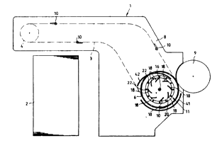
Figs. 1 and 2 illustrate a detivery device 1 of a paper sheet rotary offset printing machine in which
~rinted paper sl~eets from thc printing cylinder 9 of the last printing unit are accepted by gripper rails
10 at~ached to chain~ 3 and are transported oYer a delivery st~ck 2 where they are s1acked. The
~ripper rails are carried on two chains 3 between the side frames 7 and 8. In the area of the arm
c~ rum 11 the chains 3 are each guided continuously over sprockets ~ and 6. Sprocket 5 is att~ched
On a s1ub shafs 13 that is rotatively mounted in side wall 7 and on

21`3978~ t ~
C
16 12 ~ l~ q ~LP~-IET STUTTG~T l ~49 6'21 g2 7~9g + 19 ~ 2 ~`IR. ~ J


whose extension outside ths side trame 7 a sprocket 12 is attached which is connected wi~h ~he
pr~nting machine drive that is not shown any turther. The sprocket 6 is also rota~ively mounted on
a s~ub ~haft 14 in the machine side trame 8 ~oncentric with sprocket 5. The stub shaft 14 is designed
to be a hollQw shaft. A shaft 16 is rotati~ely mounted concentric to the stub shaf~s 13 and 14 and i~
extended through the holloul stub shaft 14 to the exterior. A motor 1~ is moun~ed on the extension
oulside the machine side fr~me ~ and is supported against the machine side frame in a known
manner. The shaft 16 runs transversaly to the paper ~h~et transport direction and is rotatively
mounted by its other shaft journal in stub shaft 13. In the rniddle of the machine ~id~h on shaft 16
a circular carrier flange 17 is rnounted in whose outer perimetsr area even1y spaced deflector blades
18 and 1g for radial Yéntilation are attached on both sid~s towards the machinR side frames 7 and
8 over the circumference of ths carrier fiange 17. The deflector blade plates 18 and 19 extend
toward~ the exterior over the full transport width and are provided at their extremity with annular
plates 25 and 26 oriented concentrically ~o the shaft 16. Circular flanges 20 and 21 ars al~o attached
on the stub shafts 13 and 14 bet~een the sprockets 5 and 6. Towards the csntre of the machine
inlst nozzles 24 are mounted on the flanges 20 and 21 orien~d concentrically to shaft 16. These
nozzles connect the ring channel 43 located within the deflector blade8 1~ betw~en deflector blade~
19 and shaft 16 with the fltmosphere by means of through holes 23 dis~ribu~d over the
circumferonce of tlanges 21 and 20. Crossbars 22 are also attached in the flan~es 20 and 21 spaced
around their circumference and at a ~r~ater radlus than that of the deflector blades 19. These
crossbars ~xtsnd across the full width bQ~ween ~he t~o flangss 20 and 21

` 2139783
lb 12 lb:Q9 ~LP~`IET STlJTTG~f?T ~ +19 6~21 92 7~39~ t~ 711 78~ 2 NR.~3~J DO~
._


Paper sheets lhat ~re transferred from printing cylinder 9 to ~ripper rails 10 on the con~inuous chains
10 (slc) are transported by the ~ripper rAils 3 (~ic) between guide plates 41 that are mounted in the
side frames 8. 7 and the outer face of the crossbars 22 on delivery drum 11. To this end the chains
3 are driven by the printing machine drive across sprocket 12, stub shaft 13, flange ~0 crossbars
22, Ilange 21 and sprockets 5 and 6. Independently ~t this the deflector blades 18 and 19 are ~riven
by means of mo~or 1~ across shaft 16 and flange 17. The deflector blades on ~he ra~ial ventilator
draw suction air through the through hol~x 23 in flan~es 20 and 21 acro~ ~he inlet noz~lee 24 into
the chann~le 43 and discharge i~ radially and circum1~rentially as blown air to the exterior. By this
msans an ad~quate cushion of air ~or stable paper sheet guiding can be achieved o~r the entir~
circumference of the delively drum. [)esired opera~lng profiles can ~e set steplessly by the aid of the
motor controller for the motor 15.

It is possible to use a motor 15 that is variable in it~ direction of drive. By this it is if necessary
possible to orient blown air coun~er to the direction of transport of She paper sheets as ~ result of
which the trailing e~ge of the paper sheet is slightly tensioned against the leading edge of the paper
shes~ that is held by the gripper rails a~ a result of which flutter effects can also be preven~ed. Even
in the event of a machine stop the motor 15 can continue to drive the def1ector blade~ 19 and 18,
thereby sustainin~ the cushion ot air.

To improvc eff~ciency it is also conceivable So attach an additional guide plate 42 above the delivsry
drum between the machine side frames. for exarnple to isolate the r~maining delivery ar~a from

2139783
16 1-' 16:~g HL~ ET ~TUTTG~PT ~ +.19 6~21 ~2 71399 +~q, 11 ;7813~14


-8


the blown air and also th~ transport area of the printing cylinder.

~igures 3 and 4 illustr~te another embodiment of the invention. Ths sprockets ~ and 6 are
stationa~ fitted on a shaft 35 that Is rotatlvely mounted in the machine side trames 7 and 8 and
runs transverse to the paper sheeS ~ransport direction. The shaft 35 is extended through machine
side frame t towards the exterior snd is in connection with the prinling machlne drive by means
o~ a sprocket 12 that Is mounted on it. I~e~ween sprockets 5 and 6 a hollow shaft 32 is rota~ively
mounted on shaft 35 and coaxially to it. Two flanges 30, 31 are rnounted on th~ hollow shaft 32
in the middle ot the machine width. At their ~nds facing the side frames ~ ~nd 8 deflector plates
28 and 29 are n~ounted for radial ventilation, coaxially to ehaft 35 and evenly spaced over the
outer circumference of flanges 30 and 31. At their extrenne end these are in turn attached to
annuiar pla~es 2~, 26 oriented coaxially to the shaft 35. Between annular plate 26 and sprocket 5
the hollow shaft 32 is connected by means of ~ dri~e belt 33 to a driven shaft 34 which is in turn
connected to an independent drive rnotor. Here a~ain the radial ventilator tormed by the d~flector
plates 28, 29 suck air from atmo~phere between sprockets 5, 6 and annular platsg 25, 26
throu~h channel 43 formed between the deflector plstes 28, 29 and hollow shaft 32 and
discharge it to atmosphere BS blown air in the direction of the paper sheet guiding plane.

Inst~ad of drive belt 33 it is ~Iso conceiv~ble to use a chain or sprocket drive.

Wi~h the embodiment of Fig. 1 and 2 it is equally conceivable to

213978~


16~12~9~ 16:1~ ~PIJET STUTTG~T ~ +49 6221 92 7~g +49 ''11 ,8~462 ~ 85 Dll~l


US8 rectangular section crossbars 36 as iilustraled in Figures ~ and 6 instead of the circular section
crossbar 22. The crossbar~ can also be ma~ched to ~hs aerodynamic requirements.

For easier assembly ~s illustrated in Fi~ure 6, ths con~iguration of the deflector piates, ~n example
of which was sho~n by w~y of ths ~econd embodimen~ in Figures 3 and 4, can also be carried out
with the aid of two flanges 37 and 38 that are ~hown sn exaggersted distanc~ apart. At the outer
sides of flanges 37 and 38 are attached the carri~r plate8 30, 3~, 40 within whose perim~ter area
the deflector plates 18, 19 are mounted as on the carrier plates 30, 31 in Fig. 4. This ~onfiguration
is conceivable both with ths drive in accordance with the first ombodirnent of Fig. 1 and 2, as is
illustrated in ~ig. 6, and In the second embodiment in which flange~ 37 and 38 are mounted on the
hollow shaft 32

Representative Drawing
A single figure which represents the drawing illustrating the invention.
Administrative Status

For a clearer understanding of the status of the application/patent presented on this page, the site Disclaimer , as well as the definitions for Patent , Administrative Status , Maintenance Fee  and Payment History  should be consulted.

Administrative Status

Title Date
Forecasted Issue Date Unavailable
(86) PCT Filing Date 1993-06-17
(87) PCT Publication Date 1994-02-03
(85) National Entry 1995-01-06
Examination Requested 1995-01-06
Dead Application 1999-06-17

Abandonment History

Abandonment Date Reason Reinstatement Date
1998-06-17 FAILURE TO PAY APPLICATION MAINTENANCE FEE

Payment History

Fee Type Anniversary Year Due Date Amount Paid Paid Date
Application Fee $0.00 1995-01-06
Maintenance Fee - Application - New Act 2 1995-06-19 $100.00 1995-05-25
Registration of a document - section 124 $0.00 1995-07-27
Maintenance Fee - Application - New Act 3 1996-06-17 $100.00 1996-05-21
Maintenance Fee - Application - New Act 4 1997-06-17 $100.00 1997-05-22
Owners on Record

Note: Records showing the ownership history in alphabetical order.

Current Owners on Record
HEIDELBERGER DRUCKMASCHINEN AG
Past Owners on Record
DETMERS, ANDREAS
FILSINGER, KARL-HEINZ
Past Owners that do not appear in the "Owners on Record" listing will appear in other documentation within the application.
Documents

To view selected files, please enter reCAPTCHA code :


To view images, click a link in the Document Description column. To download the documents, select one or more checkboxes in the first column and then click the "Download Selected in PDF format (Zip Archive)" or the "Download Selected as Single PDF" button.

List of published and non-published patent-specific documents on the CPD .

If you have any difficulty accessing content, you can call the Client Service Centre at 1-866-997-1936 or send them an e-mail at CIPO Client Service Centre.


Document
Description 
Date
(yyyy-mm-dd) 
Number of pages   Size of Image (KB) 
Description 1998-07-29 9 333
Claims 1998-07-29 4 156
Cover Page 1995-08-17 1 19
Abstract 1994-02-03 1 62
Description 1994-02-03 9 344
Claims 1994-02-03 4 120
Drawings 1994-02-03 6 138
Representative Drawing 1997-06-19 1 5
International Preliminary Examination Report 1995-01-06 28 836
Examiner Requisition 1996-05-10 2 77
Prosecution Correspondence 1996-09-10 14 502
Fees 1997-05-22 1 64
Fees 1996-05-21 1 52
Fees 1995-05-25 1 46