Note: Descriptions are shown in the official language in which they were submitted.
2139798
1 Pivoting and Variable Height Table
BACKGROUND
The present invention generally relates to a device
for allowing an object to be pivoted about a vertical axis
and to be positioned at variable heights, specifically to
a device for pivoting and variably adjusting the height
of a table, and particularly to a device for pivoting a
table over a bed or a movable nightstand at any desired
height.
While reclining or sitting in bed, it is often
desired to have a table positioned relative to the bed
for providing a support for various objects such as food
containers, writing tablets, or the like. Further, it is
desirable that the table be located out of the way when
15 it is not desired to be positioned relative to the bed.
Additionally, it is desirable that the table can be
positioned at variable heights depending upon the
particular use of the table, the size and comfort of the
21337~8
. . :
1 user, and like factors. A table pivotable and height
variable relative to a nightstand which is movable
relative to the bed has been found to be a form of
furniture which satisfies this market niche. With the
increasing awareness of this type of furniture, an
increasing need exists for devices for allowing tables or
like objects to be pivoted about a vertical axis and to
be positioned at variable heights and which are relatively
inexpensive to fabricate and assemble, which are not
10 prone to wear, which are easily operated, and which are
relatively simple in design having minimal components and
relatively few moving parts.
SUMMARY
The present invention solves this need and other
15 problems in the furniture field by providing, in the most
preferred form, at least first and second fingers movable
between a first position of a size for movement in the
inner passage of a vertical pillar and past annular
shoulder portions therein and a second position of a size
20 for abutting with one of the annular shoulder portions of
the inner passage for preventing vertical movement of the
fingers therebeyond and allowing the fingers to move on
the annular shoulder portion in a circular path.
In a further aspect of the present invention, the
25 pillar is formed by a plurality of indexing spacers
stacked along a vertical axis in a vertical tube, with
each of the spacers including an inner surface having an
-annular shoulder extending generally perpendicular to the
vertical axis.
It is thus an object of the present invention to
provide a novel device for allowing an object to be
pivoted about an axis and variably positioned along that
axis.
It is further an object of the present invention to
35 provide such a pivotable and variable positioning device
which is formed from relatively easily fabricated
components.
213979~
.
1 It is further an object of the present invention to
provide such a pivotable and variable positioning device
which can be easily assembled.
It is further an object of the present invention to
provide such a pivotable and variable positioning device
which is not prone to wear.
It is further an object of the present invention to
provide such a pivotable and variable positioning device
which is easily operated.
It is further an object of the present invention to
provide such a pivotable and variable positioning device
including minimal components.
It is further an object of the present invention to
provide such a pivotable and variable positioning device
15 including relatively few moving parts.
These and further objects and advantages of the
present invention will become clearer in light of the
following detailed description of an illustrative
embodiment of this invention described in connection
20 with the drawings.
DESCRIPTION OF THE DRAWINGS
The illustrative embodiment may best be described by
reference to the accompanying drawings where:
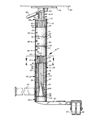
Figure 1 shows a perspective view of a device for
25 allowing a table to be pivoted about a vertical axis and
to be positioned at variable heights relative to a bed and
a movable nightstand according to the preferred teachings
of the present invention, with portions shown in phantom.
Figure 2 shows a cross-sectional view of the table
30 pivoting and variable height device of Figure 1 with the
fingers of the lift sub-assembly in their extended
position, with portions shown in phantom.
Figure 3 shows a partial cross-sectional view of the
table pivoting and variable height device of Figure 1 with
35 the fingers of the lift sub-assembly in their retracted
position.
2139798
_. .
1 Figure 4 shows a cross-sectional view of the table
pivoting and variable height device of Figure 1 according
to section line 4-4 of Figure 2.
Figure 5 shows a top plan view of the bottom bushing
of the table pivoting and variable height device of
Figure 1.
All figures are drawn for ease of explanation of
the basic teachings of the present invention only;
the extensions of the Figures with respect to number,
10 position, relationship, and dimensions of the parts to
form the preferred embodiment will be explained or will be
within the skill of the art after the following teachings
of the present invention have been read and understood.
Further, the exact dimensions and dimensional proportions
15 to conform to specific force, weight, strength, and
similar requirements will likewise be within the skill
of the art after the following teachings of the present
invention have been read and understood.
Where used in the various figures of the drawings,
20 the same numerals designate the same or similar parts.
Furthermore, when the terms "top", "bottom", "first",
"second", "inside", "outside", "outer", "inner",
"upper", "lower", "height", "width", "length", "end",
"side", "horizontal", "vertical", "axial", "radial",
25 "longitudinal", "lateral", and similar terms are used
herein, it should be understood that these terms have
reference only to the structure shown in the drawings as
it would appear to a person viewing the drawings and are
utilized only to facilitate describing the invention.
30 DESCRIPTION
A device for allowing a shelf or like object to be
pivoted about a vertical axis and to be positioned at
variable heights is shown in the drawings according to the
preferred teachings of the present invention and generally
35 designated 10. In the most preferred form of the present
invention, device 10 is utilized in connection with a
nightstand 12 which is movable relative to a bed 14.
21397~8
1 Specifically, bed 14 includes an elongated track 16 in
which a carriage, not shown, is movably mounted. Device
10 includes a vertical tube 18 which is cylindrical in
the most preferred form. A frame member 20 is secured to
and extends generally perpendicular from the lower end of
tube 18. Casters 22 are secured to the free end of frame
member 20. The bottom of nightstand 12 rests upon and is
secured to frame member 20 and one end of nightstand 12
abuts with tube 18, with nightstand 12 secured to tube 18
10 and frame member 20 by any suitable means. An arm 24
extends radially from tube 18 in a direction opposite to
frame member 20 and in the preferred form slightly
vertically above the lower end of tube 18. The outer,
free end of arm 24 is suitably secured to the carriage
15 movably mounted in track 16. Thus, nightstand 12 is
supported and movable by casters 22 and the carriage.
Device 10 according to the preferred teachings of the
present invention includes a plurality of indexing spacers
26. Spacers 26 are generally tubular in configuration
20 and include an outer surface 28 of a size and shape
corresponding to and for slideable receipt inside tube 18
which is cylindrical in the most preferred form. Spacers
26 further include an upper end 30 and a lower end 32.
The inner surface of spacer 26 includes a first portion
25 34 which in the most preferred form is cylindrical of a
diameter less than that of surface 28. Portion 34 extends
from upper end 30 towards but spaced from lower end 32 and
in the most preferred form extends approximately midway
between ends 30 and 32. The inner surface of spacer 26
30 further includes a second shoulder portion 36 which
extends generally perpendicular to the vertical,
longitudinal axis of spacer 26, of surface 28, and
portion 34 and in the most preferred form having a radial
thickness approximately double the radial thickness
35 between surface 28 and portion 34. The inner surface of
spacer 26 further includes a third portion 38 in the
preferred form which is cylindrical in the most preferred
2139798
1 form of a diameter equal to the inner edge of shoulder
portion 36. In the preferred form, portion 38 extends
from portion 36 towards but spaced from lower end 32 and
in the most preferred form extends approximately 5% of
the height between ends 30 and 32. The inner surface
of spacer 26 further includes a fourth portion 40 of a
decreasing size from portion 38 to end 32 and in the most
preferred form is of a conical shape. Specifically,
fourth portion 40 in the preferred form has a diameter
10 and shape equal to the lower end of portion 38 at its
interconnection thereto. Fourth portion 40 in the
preferred form has a diameter and shape at end 32 equal
to portion 34 at end 30.
In the most preferred form, end 30 has
15 circumferentially spaced lugs 42 extending axially
therefrom in a direction away from end 32. End 32 has
circumferentially spaced cavities 44 extending axially
therefrom in a direction toward end 30. Cavities 44 have
a size, shape, and position for slideable receipt of lugs
20 42 in the most preferred form with a close tolerance fit.
In the most preferred form, a plurality of spacers 26 are
slideably received and stacked end-on-end along the
vertical axis in tube 18, with end 32 of the lowest spacer
26 being supported above and in the preferred form on
25 frame 20, with end 32 of the second lowest spacer 26 being
supported on end 30 of the lowest spacer 26 with lugs 42
of the lowest spacer 26 received in cavities 44 of the
second lowest spacer 2~, and so on. In the most preferred
form, lugs 42 are not in axial alignment with cavities 44
30 in each spacer 26.
In the preferred teachings of the present invention,
device 10 further includes a bottom bushing 50 which is
generally tubular in configuration. In the preferred
form, bushing 50 includes an outer surface 52 of a size
35 and shape corresponding to and for slideable receipt
inside tube 18 which is cylindrical in the most preferred
form. Bushing 50 further includes an upper end 54 and a
~1~9798
1 lower end 56. Bushing 50 also includes a cylindrical
inner surface 58 of a diameter less than the inner edge of
shoulder portion 36 of spacers 26 in the preferred form.
Outer surface 52 includes circumferentially spaced troughs
60 extending axially the full height between ends 54 and
56. Troughs 60 have a size, shape, and position for
slideable receipt of lugs 42 of spacers 26 in the most
preferred form with a close tolerance fit. Outer surface
52 also includes circumferentially spaced cut-outs 62
10 extending axially the full height between ends 54 and 56
and circumferentially spaced from troughs 60. End 54 has
circumferentially spaced lugs 64 extending axially
therefrom in a direction away from end 56. Lugs 64 have
a size, shape, and position for slideable receipt in
15 cavities 44 in the most preferred form with a close
tolerance fit. In the most preferred form, bushing 50
is slideably received in tube 18, with end 56 being
supported on end 30 of the upper spacer 26 in tube 18,
with lugs 42 of the upper spacer 26 received in troughs
20 60 of bushing 50.
Device 10 according to the preferred teachings of
the present invention includes a plurality of positional
spacers 66 stacked end-on-end in tube 18. In the most
preferred form, positional spacers 66 are of identical
25 construction to spacers 26. The end 32 of the lowest
spacer 66 is supported on end 54 of bushing 50, with lugs
64 of bushing 50 received in cavities 44 of the lowest
spacer 66.
Device 10 according to the preferred teachings of
30 the present invention further includes a top bushing 68.
In the most preferred form, bushing 68 is generally of
identical construction as bushing 50 but includes an
annular lip 70 integrally secured to upper end 54 thereof.
Annular lip 70 has a size and shape greater than outer
35 surface 52 and generally equal and corresponding to the
outer surface of tube 18. End 56 of bushing 68 is
supported on end 30 of the upper spacer 66, with lugs 42
2133798
--8--
1 of the upper spacer received in troughs 60 of bushing 68.
Additionally, the lower axial end of lip 70 of bushing 68
abuts with and is supported on the upper end of tube 18.
In the most preferred form, a set screw 72 extends through
tube 18 and is threaded in bushing 68 to prevent slideable
removal of bushing 68 from tube 18 and to prevent rotation
of bushing 68 in tube 18. Due to the slideable receipt of
lugs 42 and 64 in cavities 44 and troughs 60, it can then
be appreciated that spacers 26 and 66 and bushing 50 are
10 then also prevented from rotating in tube 18. Likewise,
since spacers 26 and 66 and bushings 50 are sandwiched
between frame 20 and bushing 68, axial sliding movement
thereof within tube 18 is further prevented. Thus, it
can be appreciated that tube 18 with spacers 26 and 66
15 and bushings 50 and 68 sandwiched therein of the most
preferred form forms a vertical pillar having an
elongated, vertically extending passage defined by inner
surfaces 58 of bushings 50 and 68 and by portions 34, 36,
38, and 40 of spacers 26 and 66.
Device 10 according to the preferred teachings of the
present invention further includes a lift sub-assembly
74. Specifically, sub-assembly 74 includes a lift tube 76
having a cylindrical outer surface of a diameter equal to
and for slideable receipt in inner surface 58 of bushings
25 50 and 68. A mounting plate 78 is integrally secured to
the upper end of lift tube 76 such as by welding. A table
top or shelf 80 is secured to plate 78 by any suitable
means such as screws and thus is operatively attached to
sub-assembly 74 and each of the components thereof. A
30 handle 82 extends through first and second axially
extending elongated slots formed on diametrically opposite
sides of tube 18 adjacent the upper end thereof. Handle
82 is pivotably mounted about a horizontal axis parallel
to a tangent of the outer surface of tube 76 to an ear 84
35 secured to the outer surface of tube 76 and/or plate 78.
A lift rod 86 is pivotably mounted to handle 82 about a
horizontal axis parallel to the pivot axis of handle 82
~13~798
.
1 to ear 84 and positioned inside of tube 76. In the most
preferred form, rod 86 has square cross sections. Thus,
by pivoting handle 82, rod 86 is reciprocated in tube 76
parallel to the longitudinal axis of tube 76. Rod 86
extends from handle 82 to closely adjacent the lower end
of tube 76.
Sub-assembly 74 further includes an adjustment cone 88
having a collar 90 slideably received on the lower end of
rod 86 and secured thereon such as by a spring pin. The
10 first ends of a multiplicity of fingers 92 are integrally
secured to collar 90, with fingers extending downwardly
and outwardly from collar 90 and rod 86. The second ends
of fingers 92 terminate in a flat surface 94 which is
perpendicular to the axis of tube 76 when the outer
15 surface of the second ends of fingers 92 have a diameter
generally equal to first portion 34. In the most
preferred form, the outer surface of the second ends of
fingers 92 adjacent to flat surface 94 terminate in
portions of a cylindrical surface 96 having a diameter
20 generally equal to first portion 34 when flat surface 94
is perpendicular to the axis of tube 76. In the most
preferred form, two pairs of fingers 92 are provided on
opposite diametric sides of rod 86 and the vertical axis
of tube 18. Fingers 92 are flexible such as by pivoting
25 at collar 90 such that the second ends can move inwardly
against their tendency or bias to move outwardly.
Handle 82 is pivotable between an upper position and
a lower position to reciprocate rod 86 within tube 76.
Due to its interconnection to handle 82 through rod 86,
30 cone 88 is in a retracted position substantially within
tube 76 as shown in Figure 3 when handle 82 is in the
upper position. In the upper or retracted position, the
lower end of tube 76 abuts with the outside surfaces of
fingers 92 and flexes them inward such that surface 96 has
35 a diameter less than the diameter of the inner edge of
shoulder portion 36. Cone 88 is in an extended position
substantially outside of tube 76 when handle 82 is in
2139798
--10--
1 the lower position. In the lower or extended position,
fingers 92 are generally in a natural position such that
surface 96 has a diameter equal to or greater than the
diameter of first portion 34 with the lower end of tube
76 either being spaced from or abutting with the outer
surface of fingers 92 intermediate their first and second
ends.
In the preferred form and as shown in Figure 3,
surface 96 in the upper position has a diameter greater
10 than the outer surface of tube 76 and inner surfaces 58
of bushings 50 and 68. Furthermore, in the most preferred
form, surface 96 has a diameter greater than the outer
surface of tube 76 and inner surfaces 58 of bushings 50
and 68 if fingers 92 are simultaneously forced inward
15 due to the abutment together of the generally axially
extending edges of fingers 92. It can then be appreciated
that at least bushings 50 and 68 and spacers 66 must
slide on tube 76 prior to the assembly of sub-assembly 74
and specifically prior to the attachment of cone 88 in
20 sub-assembly 74 as cone 88 is unable to slide through
bushing 50 after assembly. Final assembly of device 10
and specifically positioning spacers 26 and 66 and
bushings 50 and 68 within tube 18 is then accomplished
after assembly of sub-assembly 74.
When handle 82 is in its lower position, surface 96
of fingers 92 abuts with the inner surface of spacers 26
and will slide downward therein until surface 94 abuts
with shoulder portion 36 and surface 96 abuts with first
portion 34 as shown in Figure 2. Due to the cylindrical
30 nature of first portion 34, inner surfaces 58, tube 76,
and surface 96, surface 94 of fingers 92 is allowed to
move on shoulder portion 36 in a circular path centered
on the vertical axis and thus tube 76 and shelf 80 are
able to rotate about a vertical axis lying along the
35 longitudinal axis of the cylindrical shape of first
portion 34, inner surfaces 58, tube 76 and surface 96.
In the most preferred form shown, device 10 allows shelf
80 to act as a table and be positioned vertically above
~139798
1 nightstand 12, vertically above bed 14, or at any desired
rotational position therebetween.
According to the teachings of the present invention,
shelf 80 can also be positioned at variable vertical
heights. Specifically to lower shelf 80, handle 82 is
pivoted from its lower position to its upper position to
retract cone 88 within tube 76. In its retracted position
as shown in Figure 3, surface 96 is smaller than the
diameter of the inner edge of shoulder portion 34 such
10 that cone 88 and the end of tube 76 are able to pass the
inner edges of shoulder portions 34 without engaging
shoulder portion 34. Sub-assembly 74 can then be slid
downward until shelf 80 is at roughly the desired vertical
height. At that time, handle 82 can be pivoted from its
15 upper position to its lower position to extend cone 88
outside of tube 76. In their extended position, fingers
92 flex outwardly towards their natural position until
surface 96 engages the inner surface of spacer 26. It
can then be appreciated that sub-assembly 74 will slide
20 downward (typically under the force of gravity) until
surface 94 engages with and abuts the next shoulder
portion 36 vertically below surface 94 when handle 82 is
pivoted to its lower position. At that time, surface 94
of fingers 92 abut with shoulder portion 36 to rotatably
25 support shelf 80 at that vertical height and to prevent
shelf 80 from moving vertically downward therebeyond.
When and if it is desired to raise shelf 80, handle
82 can be pivoted from its lower position to its upper
position such that surface 96 has a size smaller than the
30 inner edge of shoulder portions 34 as shown in Figure 3.
Then, sub-assembly 74 can be lifted to slide tube 76 in
spacers 26 until shelf 80 is at roughly the desired
vertical height. At that time, handle 82 can be pivoted
from its upper position to its lower position to extend
35 cone 88 outside of tube 76. In their extended position,
fingers 92 flex outwardly towards their natural position
until surface 96 engages the inner surface of spacer 26.
21397~8
-12-
1 It can then be appreciated that sub-assembly 74 will
slide downward (typically under the force of gravity)
until surface 94 engages with the next shoulder portion
36 vertically below surface 94 when handle 82 is pivoted
to its lower position. At that time, surface 94 of
fingers 92 abuts with shoulder portion 36 to rotatably
support shelf 80 at that vertical height and to prevent
shelf 80 from moving vertically lower. Alternately,
without moving handle 82, sub-assembly 74 can be lifted
10 to slide tube 76 in spacers 26. As tube 76 is slid,
surface 96 will slide within first portion 34 of spacer
26 in which surface 94 originally abutted with shoulder
portion 36 and then slide within fourth portion 40 of the
next vertically upper spacer 26. Fourth portion 40 will
15 then cam fingers 92 inward in a direction from their
natural position. After the free ends of fingers 92 pass
through third portion 38, fingers 92 will flex outwardly
towards their natural position until surface 96 abuts
with first portion 34 of spacer 26. Sub-assembly 74 can
20 be raised until surface 94 is positioned above shoulder
portion 36 at the desired height of shelf 80.
It can be appreciated that inner surfaces 58 of
bushings 50 and 68 slideably support tube 76 inside of
tube 18 for reciprocation parallel to the longitudinal
25 axis of tube 18. Thus, tube 76 and cone 88 will always
be centered in the inner surfaces of spacers 26 and 66.
Further since the inner surfaces of spacers 26 and 66 are
spaced from tube 76, sliding and rotational friction of
tube 76 in tube 18 is minimized. Further, as set forth
30 previously in the most preferred form, fingers 92 can not
be flexed inwardly to a size smaller than inner surface
58 of bushing 50. Due to the capture of bushing 50 in
tube 18 by its sandwiching with spacers 26 and 66 between
frame 20 and bushing 68, bushing 50 prevents fingers 92
35 from being pulled through inner surface 58 of bushing 50
and thus prevents further removal of sub-assembly 74
therebeyond. Thus, the vertical position of sub-assembly
74 is restricted to where fingers 92 are at least
213~7~
-13-
1 partially located in spacers 26 and specifically
intermediate frame 20 and bushing 50.
It can further be appreciated that device 10 according
to the preferred teachings of the present invention is
easily assembled from a minimal number of easily
fabricated components which are not prone to wear.
Specifically, the use of a plurality of spacers 26 and 66
and bushings 50 and 68 rather than a single component is
advantageous in that the molds for spacers 26 and 66 and
10 bushings 50 and 68 are less complex and there is less
chance of warpage or other fabrication defects. In this
regard, bushings 50 and 68 could be formed by extrusion to
reduce capital costs. Additionally, tubes 18 and 76, rod
86, as well as other components are fabricated from off
15 the shelf stock such that molds and other capital costs
are minimized. Additionally, the relatively movable
components, i.e. handle 82 relative to tube 76, rod 86
relative to handle 82, fingers 92 relative to each other
and to spacers 26, and tube 74 relative to the internal
20 passage of the vertical pillar formed by tube 18 and inner
surfaces 58 of bushings 50 and 68 in the preferred form,
are not prone to wear or breakage from use. Further,
assembly of spacers 26 and 66 and bushings 50 and 68
together is simply accomplished by interfitting lugs 42
25 and 64 in cavities 44 and troughs 60 and their assembly
with lift sub-assembly 74 in tube 18 is performed by
their slideable receipt in tube 18 and the securement
of set screws 72.
Thus since the invention disclosed herein may be
30 embodied in other specific forms without departing from
the spirit or general characteristics thereof, some of
which forms have been indicated, the embodiments
described herein are to be considered in all respects
illustrative and not restrictive. The scope of the
35 invention is to be indicated by the appended claims,
rather than by the foregoing description, and all changes
which come within the meaning and range of equivalency of
the claims are intended to be embraced therein.