Language selection

Search

Patent 2140189 Summary

Third-party information liability

Some of the information on this Web page has been provided by external sources. The Government of Canada is not responsible for the accuracy, reliability or currency of the information supplied by external sources. Users wishing to rely upon this information should consult directly with the source of the information. Content provided by external sources is not subject to official languages, privacy and accessibility requirements.

Claims and Abstract availability

Any discrepancies in the text and image of the Claims and Abstract are due to differing posting times. Text of the Claims and Abstract are posted:

  • At the time the application is open to public inspection;
  • At the time of issue of the patent (grant).
(12) Patent: (11) CA 2140189
(54) English Title: APPARATUS FOR CORRECTING SKEW OF A TRAVELING CRANE
(54) French Title: APPAREIL UTILISE POUR CORRIGER L'OBLIQUITE D'UN PONT ROULANT
Status: Expired
Bibliographic Data
(51) International Patent Classification (IPC):
  • B66C 17/00 (2006.01)
  • B66C 9/16 (2006.01)
  • B66C 13/00 (2006.01)
(72) Inventors :
  • THORSEN, GEORGE E. (United States of America)
(73) Owners :
  • MHE TECHNOLOGIES, INC. (United States of America)
(71) Applicants :
(74) Agent: RIDOUT & MAYBEE LLP
(74) Associate agent:
(45) Issued: 1999-02-16
(22) Filed Date: 1995-01-13
(41) Open to Public Inspection: 1996-05-22
Examination requested: 1995-01-13
Availability of licence: N/A
(25) Language of filing: English

Patent Cooperation Treaty (PCT): No

(30) Application Priority Data:
Application No. Country/Territory Date
08/342,857 United States of America 1994-11-21

Abstracts

English Abstract


An overhead traveling crane adapted to be supported on a
pair of spaced apart, generally parallel first and second rails,
the crane comprising a frame having opposite first and second
ends, a first drive wheel which is rotatably mounted on the first
end of the frame and which is adapted to roll along the first
rail, a first idler wheel which is rotatably mounted on the first
end of the frame and which is adapted to roll along the first
rail, a second drive wheel which is rotatably mounted on the
second end of the frame and which is adapted to roll along the
second rail, a second idler wheel which is rotatably mounted on
the second end of the frame and which is adapted to roll along
the second rail, a first motor mounted on the frame and drivingly
connected to the first drive wheel, a second motor mounted on the
frame and drivingly connected to the second drive wheel, an idler
shaft connecting the idler wheels such that the idler wheels
rotate at the same speed, a hoist moveable along the frame in a
direction generally perpendicular to the rails, and a load
engaging mechanism which is raised and lowered by the hoist.


French Abstract

La présente invention a pour objet un pont roulant destiné à être supporté par un premier et un deuxième rails espacés et essentiellement parallèles; le pont roulant est constitué des éléments suivants : un bâti comportant une première et une deuxième extrémités opposées, une première roue motrice en montage rotatif sur la première extrémité du bâti et destinée à rouler le long du premier rail, une première roue intermédiaire en montage rotatif sur la première extrémité du bâti et destinée à rouler le long du premier rail, une deuxième roue motrice en montage rotatif sur la deuxième extrémité du bâti et destinée à rouler le long du deuxième rail, une deuxième roue intermédiaire en montage rotatif sur la deuxième extrémité du bâti et destinée à rouler le long du deuxième rail, un premier moteur monté sur le bâti et en couplage mécanique avec la première roue motrice, un deuxième moteur monté sur le bâti et en couplage mécanique avec la deuxième roue motrice, un arbre d'interconnexion reliant les roues intermédiaires et assurant leur rotation solidaire à une même vitesse, un premier treuil mobile en déplacement le long du bâti dans une direction essentiellement perpendiculaire aux rails, ainsi qu'un mécanisme de prise de la charge dont le relèvement et l'abaissement sont effectués par le treuil.

Claims

Note: Claims are shown in the official language in which they were submitted.

-7-
CLAIMS
1. An overhead traveling crane adapted to be
supported on a pair of spaced apart, generally parallel
first and second rails, said crane comprising
a frame having opposite first and second ends,
a first drive wheel which is rotatably mounted on
said first end of said frame and which is adapted to
roll along the first rail,
a first idler wheel which is rotatably mounted on
said first end of said frame and which is adapted to
roll along the first rail, said first idler wheel
having a radially outwardly extending flange with an
inside wall facing outwardly and facing the first rail,
a second drive wheel which is rotatably mounted on
said second end of said frame and which is adapted to
roll along the second rail,
a second idler wheel which is rotatably mounted on
said second end of said frame and which is adapted to
roll along the second rail, said second idler wheel
having a radially outwardly extending flange with an
inside wall facing outwardly and facing the second
rail,
a first motor mounted on said frame and drivingly
connected to said first drive wheel,
a second motor mounted on said frame and drivingly
connected to said second drive wheel,
an idler shaft connecting said idler wheels such
that said idler wheels rotate at the same speed,
a hoist moveable along said frame in a direction
generally perpendicular to the rails, and
a load engaging mechanism which is raised and
lowered by said hoist.

2. A crane as set forth in Claim 1 wherein said
inside wall of said first flange angles away from the
first rail, and wherein said inside wall of said second
flange angles away from the second rail.

-8-
3. A crane as set forth in Claim 1 wherein said
frame includes spaced apart tracks extending generally
perpendicular to the rails, and wherein said hoist is
supported for movement along said tracks.

4. A crane as set forth in Claim 1 wherein said
load engaging mechanism is a hook.

5. A crane as set forth in Claim 1 wherein said
frame includes a pair of spaced apart, generally
parallel bridge members.

6. A crane as set forth in Claim 1 and further
comprising at least one journal box mounted on said
frame, and wherein said journal box rotatably supports
said idler shaft.

-9-
7. An overhead traveling crane comprising
a pair of spaced apart, generally parallel first
and second rails,
a frame having opposite first and second ends,
a first truck attached to said first end of said
frame,
a first drive wheel which is rotatably mounted on
said first truck and which rolls along said first rail,
a first idler wheel which is rotatably mounted on
said first truck and which rolls along said first rail,
said first idler wheel having a radially outwardly
extending flange with an inside wall facing outwardly
and facing said first rail,
a second truck attached to said second end of said
frame,
a second drive wheel which is rotatably mounted on
said second truck and which rolls along said second
rail,
a second idler wheel which is rotatably mounted on
said second truck and which rolls along said second
rail, said second idler wheel having a radially
outwardly extending flange with an inside wall facing
outwardly and facing said second rail,
a first motor mounted on said frame and drivingly
connected to said first drive wheel,
a second motor mounted on said frame and drivingly
connected to said second drive wheel,
an idler shaft connecting said idler wheels such
that said idler wheels rotate at the same speed,
a hoist moveable along said frame in a direction
generally perpendicular to said rails, and
a load engaging mechanism which is raised and
lowered by said hoist.

8. A crane as set forth in Claim 7 wherein said
inside wall of said first flange angles away from said
first rail, and wherein said inside wall of said second
flange angles away from said second rail.

-10-
9. A crane as set forth in Claim 7 wherein said
frame includes spaced apart tracks extending generally
perpendicular to said rails, and wherein said hoist is
supported for movement along said tracks.

10. A crane as set forth in Claim 7 wherein said
load engaging mechanism is a hook.

11. A crane as set forth in Claim 7 wherein said
frame includes a pair of spaced apart, generally
parallel bridge members extending between said trucks.

12. A crane as set forth in Claim 7 and further
comprising at least one journal box mounted on said
frame, and wherein said journal box rotatably supports
said idler shaft.

13. A crane as set forth in Claim 1 wherein each
of said idler wheels has a cylindrical outer surface.

14. A crane as set forth in Claim 7 wherein each
of said idler wheels has a cylindrical outer surface.

-11-
15. An overhead traveling crane comprising
a pair of spaced apart, generally parallel first
and second rails,
a frame having opposite first and second ends,
a first truck attached to said first end of said
frame,
a first drive wheel which is rotatably mounted on
said first truck and which rolls along said first rail,

a first idler wheel which is rotatably mounted on
said first truck and which rolls along said first rail,
said first idler wheel having a cylindrical outer
surface and a radially outwardly extending flange with
a first inside wall facing outwardly and facing said
first rail, said first inside wall being angled away
from said first rail,
a second truck attached to said second end of said
frame,
a second drive wheel which is rotatably mounted on
said second truck and which rolls along said second
rail,
a second idler wheel which is rotatably mounted on
said second truck and which rolls along said second
rail, said second idler wheel having a radially
outwardly extending flange with a second inside wall
facing outwardly and facing said second rail, said
second inside wall being angled away from said second
rail,
a first motor mounted on said frame and drivingly
connected to said first drive wheel,
a second motor mounted on said frame and drivingly
connected to said second drive wheel,
an idler shaft connecting said idler wheels such
that said idler wheels rotate at the same speed,
a hoist moveable along said frame in a direction
generally perpendicular to said rails, and
a load engaging mechanism which is raised and
lowered by said hoist.

-12-
16. A crane as set forth in Claim 15 wherein said
frame includes spaced apart tracks extending generally
perpendicular to said rails, and wherein said hoist is
supported for movement along said tracks.

17. A crane as set forth in Claim 15 wherein said
load engaging mechanism is a hook.

18. A crane as set forth in Claim 15 wherein said
frame includes a pair of spaced apart, generally
parallel bridge members extending between said trucks.

19. A crane as set forth in Claim 15 and further
comprising at least one journal box mounted on said
frame, and wherein said journal box rotatably supports
said idler shaft.

Description

Note: Descriptions are shown in the official language in which they were submitted.


- . . CA 02140189 1997-12-01


APPARATUS FOR CORRECTING SKEW OF A TRAVELING CRANE

FIELD OF THE INVENTION
The invention relates to overhead traveling cranes
which operate on spaced apart rails and, in particular,
to the correction of skewing of such cranes on their
rails.

BACKGROUND OF THE INVENTION
Overhead cranes which travel on wheels along
spaced apart, generally parallel rails are subject to
the continuous problem of the skewing of the crane on
the rails. The forces causing skewing are due to rail
displacement caused by rail support changes, rail
deterioration resulting from improper adjustment of
acceleration and deceleration forces of drive motors
and brakes, and variations in traction due to rail
contamination from moisture vapor and airborne
particles. The skewing itself exacerbates the problem
since it produces stresses on the rail structure which
contribute further to the displacement of the rails.
Moreover, the skewing causes severe stressing and wear
of the crane wheels. The end result of rail
displacement and deterioration and consequent increased
skewing is a short wear life of the rails requiring
their relatively frequent replacement and very frequent
replacement of the wheels.
Various prior art solutions to the skewing problem
have been developed. These include controls in which a
sensing device is used for detecting skew and adjusting
the drive motors of the crane to correct the skew.
Another approach, upon sensing skew of the bridge, is
to either apply a friction drag to the leading skewed
end of the bridge or activate a wheel brake on the
leading drive wheel of the skewed bridge. A further
solution, disclosed in U.S. Pat. No. 3,095,829, in a
crane having drive wheels driven and controlled
independently, is to decrease the clearance between the
rail and the outside flange of each of the drive

- CA 02140189 1997-12-01


wheels. Consequently, the outside flange of the
leading drive wheel, when the crane moves to a skewed
position, will contact the outer side of the rail on
which it rides and cause that wheel as well as its
S drive system to slow down due to the resulting friction
and thereby correct the skew. The skew sensing devices
used in prior art skew correction methods have
typicallybeen contacting devices such as rollers which
are connected to switches and proximity type switches
which will provide an output signal indicative of their
distance from the rail.
U.S. Patent No. 5,080,021 discloses an apparatus
for correcting skew of a traveling crane operating on
spaced apart rails in which the drive wheels always
rotate at the same speed.

CA 02140189 1997-12-01


SUMMARY OF THE INVENTION
The invention provides an improved apparatus for
correcting skew of a traveling crane in which the drive
wheels are driven independently. Skew is substantially
eliminated by connecting the idler wheels with an idler
shaft so that the idler wheels rotate at the same
speed. Preferably, the wheels have inside flanges as
described in U.S. Patent No. 5,080,021, which is
discussed above. The idler shaft drives the idler
wheel at the light end of the frame at the same speed
as the idler wheel at the heavy end. This essentially
prevents skewing when the crane is carrying a heavy
load. Also, the idler shaft pulls the heavy end during
acceleration.
This arrangement allows the crane to be operated
at substantially higher speeds than would otherwise be
possible, and allows reduction of the wheel base
relative to the bridge span. Larger wheels (which
provide better traction) and more powerful drive trains
can be employed. Rail, runway support and building
life are increased.
Other features and advantages of the invention
will become apparent to those skilled in the art upon
review of the following detailed description, claims
and drawings.

' CA 02140189 1997-12-01
.

--4--
DESCRIPTION OF THE DRAWINGS
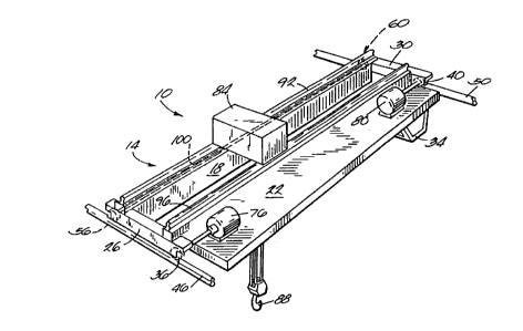
Fig. 1 is a perspective view of a traveling crane
embodying the invention.
Fig. 2 is a plan view partially broken away.
Fig. 3 is a view taken along line 3--3 of Fig. 2
and partially broken away.
Before one embodiment of the invention is
explained in detail, it is to be understood that the
invention is not limited in its application to the
details of the construction and the arrangements of
components set forth in the following description or
illustrated in the drawings. The invention is capable
of other embodiments and of being practiced or being
carried out in various ways. Also, it is to be
understood that the phraseology and terminology used
herein is for the purpose of description and should not
be regarded as limiting.

DETAILED DESCRIPTION OF THE PREFERRED EMBODIMENT
An overhead traveling crane 10 embodying the
invention is shown in the drawings. The crane 10
comprises (see Fig. 1) a frame 14 including a pair of
bridge cross-members 18 and 22, and trucks 26 and 30 at
opposite ends of the cross-members 18 and 22. An
operator's cab 34 is suspended from the frame 14.
Drive wheels 36 and 40 are respectively rotatably
mounted on the trucks 26 and 30 in engagement with
rails 46 and 50, respectively, so that the rails
support the crane 10. Additional non-driven or idler
wheels 56 and 60 are respectively rotatably mounted on
the trucks 26 and 30 in engagement with the rails 46
and 50, respectively, for further support of the crane
10. The rails 46 and 50 are respectively mounted on
beams 66 and 70 (see Fig. 3) or other suitable
foundation means. The rotatable engagement of the
drive and idler wheels with the rails permits travel of
the crane 10 along the rails. Motors 76 and 80 (see
Figs. 1 and 2) are mounted on the frame 14 and drive

CA 02140189 1997-12-01


the wheels 36 and 40, respectively. A hoist 84 (see
Fig. 1) having a load hook 88 is supported for travel
on tracks 92 and 96 which are respectively mounted on
the cross-members 18 and 22 of the crane 10. The hoist
84 also includes motors (not shown) for moving the
hoist along the tracks and for raising and lowering the
load hook 88. The crane 10 may be operated by well-
known controls, not shown, which control the operation
of the motors 76 and 80, the movement of the hoist on
the tracks, and the raising and lowering of the load
hook 88.
In order to substantially eliminate skewing of the
crane 10, the wheels 36, 40, 56 and 60 have inner
steering flanges as described in U.S. Patent No.
5,080,021, which is assigned to the assignee hereof,
and the idler wheels 56 and 60 are connected by an
idler shaft 100 (see Figs. 2 and 3) so that the wheels
56 and 60 rotate at the same speed. Specifically, each
of the wheels 56 and 60 has a cylindrical outer surface
101 and a radially outwardly extending flange with an
outwardly-facing inside surface 102. The inside
surface 102 of the wheel 56 faces the rail 46 and is
angled away from the rail 46. The inside surface 102
of the wheel 60 faces the rail 50 and is angled away
from the rail 50. The idler shaft 100 is supported on
bridge member 18 by journal boxes 104 and 108. When
the crane 10 is carrying a heavy load adjacent one end
of the bridge or frame 14, the idler shaft 100 drives
the idler wheel at the light end of the frame 14 at the
same speed as the idler wheel at the heavy end, and the
idler shaft 100 pulls the heavy end during
acceleration. This allows the crane 10 to be operated
at substantially higher speeds than would otherwise be
possible, and allows reduction of the wheel base
relative to the bridge span. Larger wheels, which
provide better traction, and a more powerful drive
train can be employed. Rail, runway support and
building life are increased.

- CA 02140189 1997-12-01


Various features of the invention are set forth in
the following claims.

Representative Drawing
A single figure which represents the drawing illustrating the invention.
Administrative Status

For a clearer understanding of the status of the application/patent presented on this page, the site Disclaimer , as well as the definitions for Patent , Administrative Status , Maintenance Fee  and Payment History  should be consulted.

Administrative Status

Title Date
Forecasted Issue Date 1999-02-16
(22) Filed 1995-01-13
Examination Requested 1995-01-13
(41) Open to Public Inspection 1996-05-22
(45) Issued 1999-02-16
Expired 2015-01-13

Abandonment History

There is no abandonment history.

Payment History

Fee Type Anniversary Year Due Date Amount Paid Paid Date
Request for Examination $400.00 1995-01-13
Application Fee $0.00 1995-01-13
Registration of a document - section 124 $0.00 1995-07-27
Maintenance Fee - Application - New Act 2 1997-01-13 $100.00 1996-11-06
Maintenance Fee - Application - New Act 3 1998-01-20 $100.00 1997-10-24
Final Fee $300.00 1998-09-30
Maintenance Fee - Application - New Act 4 1999-01-13 $100.00 1999-01-12
Registration of a document - section 124 $50.00 1999-10-26
Maintenance Fee - Patent - New Act 5 2000-01-13 $150.00 2000-01-04
Maintenance Fee - Patent - New Act 6 2001-01-15 $150.00 2001-01-03
Maintenance Fee - Patent - New Act 7 2002-01-14 $150.00 2002-01-09
Maintenance Fee - Patent - New Act 8 2003-01-13 $150.00 2002-12-27
Maintenance Fee - Patent - New Act 9 2004-01-13 $200.00 2004-01-02
Registration of a document - section 124 $100.00 2004-09-08
Maintenance Fee - Patent - New Act 10 2005-01-13 $250.00 2004-12-21
Maintenance Fee - Patent - New Act 11 2006-01-13 $250.00 2006-01-05
Maintenance Fee - Patent - New Act 12 2007-01-15 $250.00 2006-12-20
Maintenance Fee - Patent - New Act 13 2008-01-14 $250.00 2008-01-11
Maintenance Fee - Patent - New Act 14 2009-01-13 $250.00 2009-01-07
Maintenance Fee - Patent - New Act 15 2010-01-13 $450.00 2010-01-11
Maintenance Fee - Patent - New Act 16 2011-01-13 $450.00 2010-12-21
Maintenance Fee - Patent - New Act 17 2012-01-13 $450.00 2012-01-09
Maintenance Fee - Patent - New Act 18 2013-01-14 $450.00 2013-01-04
Maintenance Fee - Patent - New Act 19 2014-01-13 $450.00 2013-12-18
Owners on Record

Note: Records showing the ownership history in alphabetical order.

Current Owners on Record
MHE TECHNOLOGIES, INC.
Past Owners on Record
HARNISCHFEGER CORPORATION
THORSEN, GEORGE E.
Past Owners that do not appear in the "Owners on Record" listing will appear in other documentation within the application.
Documents

To view selected files, please enter reCAPTCHA code :


To view images, click a link in the Document Description column. To download the documents, select one or more checkboxes in the first column and then click the "Download Selected in PDF format (Zip Archive)" or the "Download Selected as Single PDF" button.

List of published and non-published patent-specific documents on the CPD .

If you have any difficulty accessing content, you can call the Client Service Centre at 1-866-997-1936 or send them an e-mail at CIPO Client Service Centre.


Document
Description 
Date
(yyyy-mm-dd) 
Number of pages   Size of Image (KB) 
Cover Page 1996-07-11 1 15
Description 1997-12-01 6 195
Claims 1997-12-01 6 176
Abstract 1996-05-22 1 31
Cover Page 1999-02-04 2 82
Drawings 1997-12-01 1 42
Description 1996-05-22 6 191
Claims 1996-05-22 4 104
Drawings 1996-05-22 1 42
Representative Drawing 1999-02-04 1 17
Representative Drawing 1998-04-08 1 18
Assignment 1999-10-26 15 588
Correspondence 1999-12-10 1 1
Assignment 2004-09-08 3 93
Correspondence 1998-09-30 1 37
Correspondence 1998-03-10 1 2
Prosecution-Amendment 1998-02-02 17 546
Assignment 1995-01-13 6 211
Prosecution-Amendment 1997-05-30 2 71
Fees 1999-01-12 1 30
Prosecution-Amendment 1997-12-01 16 518
Fees 1997-10-24 1 36
Fees 2000-01-04 1 29
Fees 2008-01-11 1 29
Fees 2009-01-07 1 36
Fees 2010-01-11 1 36
Fees 2010-12-21 1 35
Fees 1996-11-06 1 36