Note: Descriptions are shown in the official language in which they were submitted.
214~
-
-- ]
This invention relates to a wellhead pipe alignment
apparatus of a type which may be mounted on the frame of a
well derrick or drilling rig for engagement with a pipe
section either being connected to or disconnected from the
upper end of another pipe section within a well bore.
In the drilling and maintenance of wells it is necessary
to install in the well, or remove from it, lengths of drill
strings or casings which are formed by pipe sections joined
together~by threaded connectors. During the installation,
for example, the upper end of the last section of pipe of the
string is maintained slightly above the level of the work
table positioned at the base of the derrick, and the next
section is raised to a suspended position so that its lower
end is located immediately above the upper end of the last
section. The bottom end of the suspended section provides
male threads to be turned into a collar having the female
threads at the upper end of the last section. Unless the
suspended section is axially aligned with the upper end of
the last section as it is engaged and turned to complete the
screw connection between the two sections, cross threading
occurs, and the damage caused can be sufficient to require
the suspended section to be removed for repair, which, of
course, is time consuming and expensive.
The most common practice used in aligning the suspended
section is to locate a workman on a platform at a position
high on the derrick adjacent the upper end of the suspended
section so that as the lower end of the section is brought
2~ a3
into engagement with the upper end of the last section, the
workman manually manipulates the upper end of the suspended
section whereby the sections are axially aligned. This
practice is dangerous, particularly during unfavorable
weather conditions, and time consuming so as to significantly
increase the cost of the operation of installing or removing
strings of tubular members from the well. Moreover, this
approach does not always assure sufficiently accurate
alignment to avoid the problems of cross threading.
While there have been developed a number of alignment
devices, none have been sufficiently successful to be
utilized to any extent in the oil fields. One major
disadvantage appears to be that some of the known devices are
of a complex nature and are thus expensive and difficult to
lS install and operate. They are also cumbersome to transport
under the conditions which frequently exist in oil fields.
Others appear to provide unsatisfactory results either in
accuracy or in their manner of mounting. Also, in drilling a
well, after setting up the derrick, the drilling string is
assembled and usually disassembled and reassembled a number
of times, and then in subsequent testing and possibly
establishing a well for pumping, pipes of a number of
different sizes are handled by the crew at the derrick.
Thus, the alignment device must be capable of accommodating
the different sizes while, of course maintaining the
longitudinal axis of the section of pipe being installed or
removed coaxial with the next lower pipe section in the bore
t3
.._
hole. It is important, therefore, that any adjusting of the
device for pipe size be capable of being carried out
accurately and quickly. In any event, the most common
practice still is that of utilizing a person to manually
align the suspended pipe sections rather than making use of a
mechanical alignment apparatus which can be controlled from
the area of the worktable.
It is an object of the present invention to provide an
apparatus which can be controlled from a ground position for
]~ containing an upper portion of a pipe section and accurately
retaining the pipe section in axially alignment with the pipe
string in the bore hole.
It is a further object of the present invention to
provide an alignment apparatus which is versatile in that it
lS may be quickly adjusted for use with a number of different
pipe sizes.
The well pipe alignment apparatus of the present
invention is of the type for mounting on a derrick framework
above a wellhead and is engagable with an upper pipe section
having a screw connection at the lower end thereof for
threading engagement with an upper end of a lower pipe
section within a well bore. The apparatus includes a
supporting frame having an outer end for connection to the
derrick framework with a head assembly carried at an inner
end of the supporting frame above the upper end of the lower
pipe section. The head assembly has a base member with pipe
engaging means for aligning a central longitudinal axis of
_ 2~4~2~3~
_ 4
the upper pipe section with the line of axis of the lower
pipe section and allowing rotation of the pipe section with
the head.
According to one aspect of the invention the pipe
engaging means includes a fixed pipe engaging guide member
and a movable arm means pivotable between an open position
and a closed position. The fixed guide member and the arm
means together have at least three pipe engaging surfaces for
engaging a pipe of a particular outer diameter at spaced
]0 points about more than 180 of the pipe circumference. Power
actuating means are provided for moving the arm means between
the open and closed positions. Stop means are selectively
adjustable between a plurality of positions for determining
the position of the pipe engaging surface of the arm means
relative to the pipe engaging surface of the fixed guide
means for thereby selectively accommodating pipes of a
plurality of different diameters.
According to another aspect of the present invention,
the pipe engaging means includes a pipe engaging guide means
and arm means movable between an open position and a closed
position with power actuating means for moving the arm means
between the open and closed positions. The pipe engaging
guide means together with the arm means in the closed
position provide at least three pipe engaging surfaces for
engaging a pipe of a particular outer diameter at spaced
points about more than ]80~ of the pipe circumference. A
first adjustment means is provided for permitting movement of
the pipe engaging guide member relative to the head assembly
toward and away from the central longitudinal axis of the
upper pipe section, and including lock means for securing the
fixed pipe in a position selected to accommodate a specific
pipe size. A second adjustment means is selectively movable
to a position for determining the position of the pipe
engaging surfaces of the arm means in the closed position in
accordance with the selected pipe size.
In the accompanying drawings, which show an embodiment
of the invention by way of example,
Figure 1 is an elevational view of the bottom portion of
a derrick on which the pipe aligning apparatus of the present
invention is mounted;
Figure 2 is a side view of the apparatus shown in Figure
1 but on an enlarged scale and also showing the apparatus in
different operational positions in relation to the section of
pipe;
Figure 3 is a plan view of the alignment apparatus of
the present invention in a lowered operative position,
Figure 4 is a side view of the head assembly of the
alignment apparatus of the present invention;
Figure 5 is a top view of the head assembly of Figure 4,
showing the head assembly in an open, pipe reception
condition,
Figure 6 is a view similar to Figure 5, but showing the
head assembly in a closed, pipe encompassing condition;
Figure 7 is a cross-section view through the head
~r~ 2~ 3
assembly of Figures 4 to 6 as seen from the line 7--7 of
Figure 4.
In the drawings, which have reference characters
denoting elements corresponding to those described
hereinafter, the reference character ]0 generally denotes the
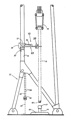
well pipe alignment apparatus of the present invention, and
in Figures ]. and 2, the apparatus ].0 is shown as being
mounted on a framework 12 of a derrick or oil well rig 1].
The derrick 11 is stationed on the ground above a well bore
]0 (not shown) into which a lower pipe section ]4, which may
actually be the top pipe section of a string consisting of a
plurality of pipe sections threadingly joined end-to end, has
been sunk into the bore. An upper pipe section ]5 is shown
as having been raised by a block system 16 to a suspended
]5 position above the lower pipe section 14. The lower pipe
section ].4 has an internally threaded collar portion or
female part ]7 at its upper end disposed above the worktable
19. The lower end or male portion ].8 of the upper pipe
section is externally threaded so that after alignment and
being slightly lowered, the upper section ].5 may be turned to
thread the threaded male portion ]8 of the upper section into
the threaded female part ]7 of the lower pipe section so as
to join the two sections together. It should be noted that
while reference is broadly made to pipe sections ].4 and 15,
which would normally be of identical structure in forming a
continuous string, the term pipe section is meant to denote
either sections to form a bore hole casing, a drill pipe, a
2~4~3
".,
pumping casing, or any other cylindrical members which may be
threaded together and lowered into a bore hole.
Turning now to Figure 2, the alignment apparatus ]0
includes a mounting bracket or structure 20 for clamping the
S apparatus to a horizontal or transverse member ]2a of the
framework ]2 in the derrick 1], the mounting structure
including lugs 2] carrying pins 22 on which an outer end 24
of a supporting frame 23 of the alignment apparatus ]0 is
mounted so as to allow the frame member and the head assembly
]0 25, which is carried on an inner end 26 of the frame member
23, to pivot about an axis A (Figure 3) from an operative
position to a retracted non-operative position. The
alignment apparatus ]0 is mounted on the derrick framework ]2
at a position above the work area so that in relation to the
lS length of the pipe section ]5, the head assembly in its
operative position engages the pipe section ]S adjacent its
upper end.
In the embodiment shown, the frame member 23 is in a
substantially horizontal position when in the active
position, and when it is in the fully retracted position 10"
(Figure 2), it is raised to a substantially vertical position
and disposed between vertical members of the derrick
framework 12 so as to be less subject to damage during the
raising and lowering of each pipe section ]S. It is
apparent, of course, that alternatively, in order to retract
the alignment apparatus to a non-operative position, the
frame could be allowed to swing downwardly so as to hang in a
2 ~ 3
'~ ~
substantially vertical position. In the illustrated
embodiment of Figure 2, however, the frame is held in the
substantially horizontal operative position by a pneumatic
cylinder 27 which is pivotally connected at its base to a lug
28 which is affixed to the mounting bracket. The outer end
of a piston rod 30 of the pneumatic cylinder 27 is pivotally
connected to a lug 31 which is affixed to the supporting
frame 23 of the pipe alignment apparatus at a location
adjacent the inner end of the frame 23.
When the piston rod 30 is fully extended, the frame 23
is supported in its generally horizontal position with the
head assembly 25 positioned over the well bore hole. As
controls 32 (Fig. 1) are activated to supply pressurized
fluid to the piston rod end of the cylinder so as to force
retraction of the piston rod 30, the frame 23 is pulled
upward as indicated by arrows 33 (Figure 2) to a retracted or
raised position 10". The controls 32 are preferably
positioned in an area adjacent the worktable 19, and in the
case where the means for raising the alignment apparatus to a
retracted position is a pneumatic cylinder, as indicated
above, the controls 32 may include a valve system which is
connected to a source air line 34. The valve system when
appropriately maneuvered places air line 34 which
communicates with a pressurized air source (not shown) to a
line 35 which extends to the pneumatic cylinder 27.
Alternatively, the controls at ground level may be electrical
for providing signals to activate a solenoid activated valve
2~4~
-
._ g
located at the level of the alignment apparatus.
The head assembly 25 includes a base member formed
primarily by a pair of parallel, horizontal upper and lower
flat base plates 36a,36b (Figure 4) which are spaced and
affixed, such as by welding to a vertical plate 37. The
vertical plate 37 is affixed to a shank 38. The purpose of
the alignment apparatus ]0 is to hold the upper end of the
pipe section 15 so that its centre is directly above the
centre of the next lower pipe section ]4. Thus, it is
necessary prior to commencing the installation of the pipe
section ]5 to ensure that the head assembly is above the
centre of the worktable ]9. The centering operation is
accomplished by adjusting the head assembly 25 relative to
the frame member 23 by way of a set-up means. As shown in
Figure 3, the inner end 26 of the frame 23 includes a pair of
spaced frame members 40,40 which are connected at their outer
ends 24 by a transverse member 4], which in turn is pivotally
connected to the framework of the derrick by pins 22 as
previously described. The members 40,40 converge inwardly
and are joined near the inner end 26 by a transverse brace
member 42. At the free ends 43,43 of members 40,40 there
are provided a pair of aligned sleeves 44,44 which
telescopically receive a cross shaft 45. Thus the cross
shaft 45 can slide longitudinal in the sleeves 44,44. The
cross shaft 45 in turn has a sleeve 46 which is perpendicular
to the axis of the aligned sleeve 44,44 and telescopically
receives the shank 38 of the head assembly 25. The sleeves
l o 2 ~
44,44 each have a winged locking screw 47 associated
therewith for engagement with the cross shaft to prevent
movement of the cross shaft in the sleeves. The sleeve 46
also has a winged locking screw 48 associated therewith for
engagement with shank 38 to prevent lengthwise movement of
the shank through sleeve 46. By loosening screw 48, the
shank 38 may be moved in either direction so as to allow
adjustment of the head assembly 25 as indicated by the arrow
50. When the desired location is established in this
direction, the screw 48 is again tightened. Thus, having
achieved the adjustment of the centre of the head assembly in
the to and fro direction 50 to correspond to the desired
centre C of the pipe section, the winged locking screws 47,47
can be released to allow lengthwise sliding of the cross
shaft 45. This permits the adjustment of the head assembly
in the side-to-side direction indicated by the arrow 51.
Having thus finalized the adjustment of the exact positioning
of the head assembly, the screws 47,47 are again tightened
and the apparatus is set up for the operation of aligning the
pipe section 15 as described above.
The head assembly 25 has mounted thereon pipe engaging
means which include a fixed pipe engaging guide member 52 and
a pair of movable arms 53,53. Looking at Figure 5 wherein
the upper horizontal base plate 36a is fully in view, it can
be seen that this base plate is provided with a substantially
semi-circular concave pipe receiving cavity or opening 54
which is of a radius somewhat greater than the radius of the
~ ~L
214~03
'~.
..,_
]-~-
largest pipe section to be handled by the pipe alignment
apparatus. The lower base plate 36b has a like opening
aligned with the opening of upper base plate 36a. Such
openings are straddled by ear portions 55,55 of each base
plate. Vertical pivot pins 56,56 each extend between the
aligned ears of the two base plates to provide an individual
pivotal mounting for each arm 53. The arms 53,53 have outer
pipe engaging portions which have pipe engaging surfaces 58
extending along an inner edge thereof, and the arms include
an inner portion which is integral with the outer portions
but extend at an obtuse angle relative to the outer portions.
Each arm 53 further has a tail or lever 57 which may be
formed integrally with the inner portion of the arm. The
lever portion 57 extends at an angle relative to the arm on
the opposite side of pivot pin 56 and consists of two
portions, a first portion 57a which has a post 60 attached to
the end thereof opposite to the arm. The post 60 extends
perpendicular to the upper side of the lever portion 57a for
the arm shown, for example, at the top of Figure 5. The post
60 for the other lever 57 (shown at the bottom of Figure 5)
extends perpendicular to the lower side of the lever portion
57a. The posts are of sufficient height to extend beyond the
outside surface of the upper and lower base plates 36,36.
The upper base plate has a notch 6] and the lower base plate
has a notch 62, so that as the arms pivot in the direction of
arrows 63 (Figure 5), the posts are free to swing outwardly
free of the base plates (Figure 6).
2~4~
~,_
12
Upper cylinder means 64a and lower cylinder means 64b
are mounted above and below the base plates 36a and 36b,
respectively (Figure 4). The base ends of the upper and
lower cylinder means 64a; 64b are pivotally attached to the
outside surfaces of base plates by pivot pins 65, and the
cylinder means each have a piston rod 66, the outer ends of
which are pivotally connected one each to the posts 60 of the
levers 57 by way of pivot pins 67 at the outer ends of the
posts 60. The cylinder means 64a, 64b are preferably
identical pneumatic cylinders which are connected in parallel
to air lines 69 (Figure ]), the lines being connected to
opposite ends of each cylinder so that as air is admitted
simultaneously to the base ends of both cylinders the piston
rods 66 are forced to the extended positions to swing the
arms 53, 53 from open position shown in Figure 5, in the
direction of the arrow 63, and eventually to the closed
position shown in Figure 6. Conversely, when the arms 53,53
are in the closed position of Figure 6 and air is admitted to
the other of the air lines 69, which is connected to the rod
ends of the cylinder, the arms are forced to the open
position (Figure 5). The activation of cylinders means 64a,
64b may thus be controlled by an operator from the controls
32 adjacent the turntable.
A second portion 57b of each lever 57 is an integral
portion of the lever which is shown as extending at an angle
to an end of the first portion beyond the post 60. The
second portion 57b functions as a stop engaging means for
2 7 ~ 3
13
controlling the closed position of the arm 53. The stop
means determines the outwardly projecting limit of the piston
rod 66 when the controls 32 have been activated to extend the
piston rod and thus close the arms 53,53. The lever portion
57b has adjacent its outer or free end the stop engaging
means in the form of a stop engaging surface 70 shown as an
arcuate shaped notch which engages a stop pin 71. The upper
and lower base plates 36a, 36b are each provided with two
series of bores or openings 72. Each series of openings 72
in one base plate is aligned with a like series of openings
in the other base plate so that the stop pin may be
selectively positioned in a pair of aligned openings and thus
extend between the base plates and be in a position to engage
within the notch 70 of the lever portion 57b as the piston
rods move to the extended position. The array or series of
each set of aligned openings presents the openings arranged
on an arc struck on a radius about the axis of the pivot pin
56 for its respective arm so that regardless of the
particular pair of openings 72 in which the stop pin for that
particular arm is located the notch will swing to a position
in which the pin 71 is received within the notch 70 forming
the stop engaging surface.
The fixed pipe guide member 52 is of a substantially Y-
shaped configuration consisting of a shank or base portion 74
and a pair of diverging leg portions 75. The inside of the
diverging leg portions form pipe engaging surfaces 76,76
extending therealong. While the member 52 has been termed a
~14~
. .,.j,
",_
]4
fixed pipe guide member, its position is in fact variable
depending on the outside diameter of the pipe being installed
or removed from the bore hole, but unlike the arms 53,53, it
does not move during the pipe enclosing or pipe releasing
operations which are achieved by the actuation of the
cylinder means 64a, 64b. The shank or base portion 74 which
has straight sides is confined between a pair of parallel
vertical guide plates 77,77 which are secured between the
inside surfaces of the upper and lower base plates 36a,36b.
The guide plates 77,77 form a channel, the longitudinal axis
of which is perpendicular to the axis of pivot A of the
supporting frame 23 and passes through the centre C of the
pipe section ]5 when the head assembly has been adjusted
properly in the direction of arrow 51 (Fig.3). The fixed
]5 pipe guide member, which is slidably received in the channel
between the guide plates 77,77, is thus movable along the
longitudinal axis of the channel toward and away from the
centre C of the pipe section. Means are provided for
allowing adjustment of the fixed guide member 52 to a number
of positions and for locking the member 52 in a selected
position. Such means are shown as consisting of two rows of
openings or bores 80a,80b in the shank 74, the rows being
parallel and spaced on opposite sides of the longitudinal
centre line thereof. There are shown three bores in one row
and two in the other, i.e. five in total, and the holes in
the two rows are not transversely disposed opposite each
other but are staggered. The upper and lower base plates
2~ 32~3
'_
]-s
36a, 36b have a pair of transversely spaced aligned holes 81
for one each aligning with the holes in one of the rows of
holes 80a, 80b. A pin 82 is provided for reception in one of
the holes of the pair 8] and to pass through a hole in one of
S the rows of holes 80a, 80b, depending on the position of the
guide member 52 along its axis of adjustment toward or away
from the pipe section ]5.
In operation, the supporting frame 23 is mounted on the
derrick 11 in a position as previously described by way of
]0 the mounting bracket 20. The head assembly is installed and
initially centered over the centre of the worktable by making
the adjustment in the side-to-side direction and the to and
fro directions, each followed by the locking of the screws
47,47 and the screw 48, respectively, as described above.
Depending on the pipe size being installed, such as the
tubular sections forming the drill rod, for example,
adjustmen-ts are made to the means which establish the fixed
position of the guide member 52, and the means which
establish the position of the pipe engaging surfaces of arms
53,53 when the arms are in their fully closed position for
the particular pipe in question. This may be readily done
if, for example, the positioning of the holes of the series
of holes 72 for determining the closed position of the arms
53,53 and the positioning of the holes in the rows of holes
81 in the shank 74 of the fixed guide 52, are arranged in a
manner such that the holes are represented as providing the
location of the surfaces 58 of the arms and 76 of the fixed
214~3
' ,.
16
guide 52 for properly encompassing a particular pipe size.
For example, as shown in Figure 5, the selection of the
position of pin 71 and of the position of the pin 82
represents the positioning of the appropriate closed position
of the arms 53,53, and the fixed position of the guide member
52 to encompass a mid sized tubular member commonly used in
well drilling, casing testing pumping pipes, etc. The holes
could in fact be marked to indicate the positioning of the
pins in the pair of holes 72 and the hole 80a or 80b for
]O accommodating a specific size of pipe.
It will be clear that when the arms 53,53 are moved to
their maximum closed position as determined by the setting of
the pins 71 for each arm, and wherein the position of the
guide 52 has already been fixed by the positioning of pin 82,
the point of contact at the surfaces 58 of the pipe engaging
surface of the arm 53,53 and the point of contact of the pipe
engaging surfaces 76 of the guide member will be located at a
radius from the centre of the pipe section ]5 approximately
equal to the radius of the outside diameter of the pipe
member being installed. Because the pipe section ]5 must be
turned, however, so as to thread its lower end into the next
lower pipe section ]4, a slight clearance must be allowed as
shown in Figure 6. Also, in view of the shape of the arms
and the guide member the point of normal contact provided by
the pipe surfaces 7~ and 58 will vary along the surfaces
depending on the pipe size in question. While it is
preferable to utilize a pair of arms as shown in the
_ 17
il]ustrated embodiment, it would be possible to use a single
arm, provided that together with the pipe guide member, the
guide surfaces are arranged to provide at least three points
of nominal contact spaced in total more than 180 about the
circumference of the pipe so that the pipe is captured within
the points of contact to thereby be held in alignment with
the pipe section below it.
During installation of a pipe section, controls 32 are
operated by a crew member so as to activate cylinders 27 to
move the head assembly to its retracted position 10" (Figure
2), this normally being done once a pipe section 15 has been
attached to the pipe section already in the bore hole. The
pipe string is then lowered and the next pipe section to be
attached is raised into position by the block system 16. The
controls 32 are then operated to lower the supporting frame
23, and thus the head assembly, into its operating position,
during which time the arms 53,53 are in their open position
(Figure 5). As the head assemb]y approaches its operating
position the pipe section 15 enters the opening 54 of the
head assembly, or it is pulled into the opening by the
closing of the arms 53,53 which is initiated by way of
controls 32. The pipe section once held in the aligned
position is rotated so as to thread the threaded lower end 18
into the threaded collar portion 17 of the pipe section 14.
This having been completed the controls 32 are operated to
initiate the opening of the arms by the retraction of the
piston rods 66 of the cylinder means 64a, 64b, and the head
18
assembly is moved to its raised or retracted position by the
simultaneous activation of the cylinder 27.
It can be readily appreciated from the above that the
alignment apparatus of this invention includes a head
assembly which allows for the accurate alignment of a pipe
section in a well head operation and allows for quick and
accurate adjustment of the head assembly to accommodate pipes
of various sizes.
The illustrated embodiment includes stop means which
provide for the selected adjustment by determining the amount
of pivot the cylinders can impart to arms 53,53 relative to
the base of the head assembly. This in turn determines the
final positioning of the pipe engaging surfaces 58,58 of the
arms in relation to the pipe engaging surfaces of the then
set guide 52 and its pipe engaging surfaces 76,76. Because
the head has been initially centred on installation, the pipe
engaging surfaces are thus properly located in relation to
the centre of the pipe section C so that when the pipe
section is held in the closed arms, the upper end of the pipe
section aligns with the centre of the pipe section 14. In
another embodiment of the invention what may be termed the
stop means for determining the position of the pipe engaging
surfaces 58,58 relative to the centre C so as to allow
adjustment for different pipe sizes could be a non-
adjustable or fixed stop. Such a fixed stop could beprovided so that when the cylinder means are activated to
close the arms 53,53, the closed position of the arms remains
1 9
the same in relation to the head regardless of the pipe size.
Instead, the previously described structure involving the
shank 38, sleeve 46, and wing nut 38, which is provided to
allow the initial adjustment of the head assembly as
indicated by arrow 50 (Figure 7), could be replaced with a
more elaborate adjustable stop means, possibly similar to the
means which allows the adjustment of the guide member 52.
Such means could be calibrated so that a selection of
movements in either direction would thus vary the
position of the pipe engaging surface 58,58 relative to the
centre C when the arms are fully closed. Thus, the closed
position of the arms is adjusted to accommodate the
particular size of pipe being used in the particular well
operation by shifting the entire head assemb]y. After the
adjustment of the head assembly as a whole, as represented by
the arrow 50, adjustment would then be made for the fixed
guide member 52 so that its pipe engaging surfaces provide
points of contact at a radius from the centre C approximately
equal to the diameter of the pipe. The calibration of
adjustment means provided by the combination of the holes
80a, 80b and the holes 81 would have to be different than
that for the first described embodiment in that the to and
fro adjustment carried out in relation to the closed position
for the arms 53,53 involves movement of the entire head
assembly which would cause movement of the fixed guide
member. Thus, the adjustment of the position of the fixed
guide member 52 would be calibrated to simultaneously
41~
~.
compensate for the head assembly movement as well as the
repositioning for a different pipe size.
Other alternative embodiments within the spirit of the
invention as defined by the claims will be apparent to those
skilled in the art.