Note: Descriptions are shown in the official language in which they were submitted.
CA 02140210 1998-10-14
A FITTING
The invention relates to a fitting for fixing a rear wall
of a drawer on drawer parts such as drawer sides or runners
of a drawer with a supporting part which can be fixed on a
drawer part and has fixing lugs which engage in receiving
openings in a corresponding part on each side of the
drawer.
In modern furniture construction drawers are known which
are made entirely by injection moulding of plastics
material, but drawers are also known in which the sides are
produced from plastics material or metal and are connected
to a rear wall also prefabricated from plastics material or
prefabricated from a metal.
In many cases, particularly in smaller production runs, it
is advantageous for the furniture manufacturer if, as far
as the width of the drawer is concerned, to not be
dependent upon prefabricated parts, i.e. in the production
of the piece of furniture he can produce drawers of any
width without special expenditure.
The object of the invention is to create a fitting which
enables a rear wall, made from a wood, extruded plastic
materials or the like which has been cut to the desired
length, to be connected by quick assembly to a drawer side
or an adapter connected to the drawer side or to a runner
of the drawer.
The object according to the invention is achieved in that
each supporting part can be coupled by means of the fixing
lugs to a holding part which can be fixed, preferably
screwed, on the rear wall, wherein the holding parts have a
fixing flange, aligned parallel with the rear wall and by
1
CA 02140210 1998-10-14
which they can be fixed on the rear wall, and a housing-
like portion, in the side wall of which are located holes
in which the fixing lugs engage.
By making use of the fitting according to the invention, it
is possible for a rear wall produced from a cut panel of
chipboard or extruded plastics material, aluminium etc. to
be incorporated into the modular system of a drawer
produced from prefabricated parts.
In accordance with one aspect of one embodiment of the
present invention, there is provided a fitting suitable for
use in attaching a rear wall of a drawer to a side part of
the drawer, the fitting comprising:
a holding part including a flange to extend in a direction
to be parallel to a rear surface of the rear wall and to be
attached thereto, and a housing portion integral with the
flange and extending laterally therefrom in a direction
such that when the flange is attached to the rear surface
of the rear wall, the housing portion is positioned at a
location of a respective lateral end of the rear wall to
form a lateral extension thereof
the housing portion including a closure wall extending
parallel to the flange in a direction to form a closed
lateral continuation of a front surface of the rear wall, a
member connecting the flange to one lateral end of the
closure wall, a side wall integral with an opposite lateral
end of the closure wall and defining therewith a corner,
the side wall extending perpendicular to the closure wall
in a direction to be rearward of the drawer, and locating
holes formed in the side wall: and
a supporting part to be attached to the side part of the
drawer, the supporting part having extending laterally
therefrom fixing lugs to engage in the locating holes to
thereby attach the holding part to the supporting part with
2
CA 02140210 1998-10-14
the housing portion positioned laterally between the side
part and the rear wall of the drawer.
In accordance with a further aspect of the present
invention there is provided a fitting member to be part of
a fitting for use in attaching a rear wall of a drawer to a
side part of the drawer, such fitting also including a
supporting part to be attached to the side part of the
drawer, the fitting member comprising a holding part to be
connectable to the supporting part, the holding part
including:
a flange to extend in a direction to be parallel to a rear
surface of the rear wall and to be attached thereto;
a housing portion integral with the flange and extending
laterally therefrom in a direction such that when the
flange is attached to the rear surface of the rear wall the
housing portion is positioned at a location of a respective
lateral end of the rear wall to form a lateral extension
thereof;
the housing portion including a closure wall extending
parallel to the flange in a direction to form a closed
lateral continuation of a front surface of the rear wall, a
member connecting the flange to one lateral end of the
closure wall, a side wall integral with an opposite lateral
end of the closure wall and defining therewith a corner,
the side wall extending perpendicular to the closure wall
in a direction to be rearward of the drawer, and locating
holes formed in the side wall.
Having thus described the invention, reference will now be
made to the accompanying drawings, illustrating preferred
embodiments and in which:
3
CA 02140210 1998-10-14
Figure 1 shows a perspective view of a drawer;
Figure 2 shows an exploded representation of a further
embodiment of a drawer;
Figures 3 and 4 each show a perspective view of a rear
wall;
Figures 5 and 6 show two different embodiments of the
holding parts;
Figure 7 shows a side view of a supporting part;
Figure 8 shows an end view of a supporting part;
Figure 9 shows a perspective view of a supporting part;
Figure 10 shows an end view of the rail mounting; and
Figure 11 shows a side view of the rail mounting on the
rear wall.
Similar numerals in the figures denote similar elements.
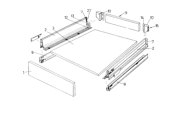
As illustrated in Figures 1 and 2, the drawer has
conventional two drawer sides 2, a front panel 1, a drawer
base 3 and a rear wall 6 or 11. The front panel 1 is
connected in the usual way to the drawer sides 2 or to the
runners 12 which are set into the drawer sides 2. The
runners 12, which run on supporting rails 9 fixed on the
side walls of the body, are provided on their rear end with
an adapter 13. The adapter is, for example, welded to
runner 12.
A adapter 13 supports the supporting part 7, which is
produced, for example, from plastics material or another
injectable material and is screwed, riveted or pushed onto
adapter 13.
The supporting parts 7 have fixing lugs 27 which are
directed towards the interior of the drawer and are of
resilient and preferably hook-shaped construction. In this
case the fixing lugs 27 point towards the central plane of
a
CA 02140210 1998-10-14
the drawer which is aligned perpendicular relative to rear
wall 6, 11 and perpendicular to drawer base 3.
The rear walls 6, 11 are both produced from a chipboard
material and have been cut to the desired length from a
longer board.
Before the drawer is assembled, each rear wall 6, 11 is
screwed on its two sides to fixing flanges 14 of the
holding parts 5, 10. In the illustrated embodiment the
fixing flanges 14 rest against the back of the rear wall 6,
11.
The holding parts 10 are the same height as the drawer
sides, whilst the holding parts 5 project beyond the drawer
sides 2 and serve for fixing a drawer rail.
Each holding part 5, 10 has a housing-like regions 15 with
a side wall 16. In the side wall 16 are located fixing
holes 17 disposed in the region of the edge 18 between side
wall 16 and a closure wall 19 of the housing-like regions
15, which closure wall is aligned parallel with the rear
wall 6, 11. The housing-like regions 15 are open towards
the rear but on the face of the rear wall 6, 11 inside the
drawer they close off the inner closure surface of the rear
wall 6, 11.
Furthermore the housing-like regions 15 are each provided
at the bottom with a cut-out 20 which receives the adapter
13 and the runner 12 when the holding parts 5, 10 are
installed.
A clip 4 which in each case holds a rail 3 can be inserted
into the holding parts 5.
5
CA 02140210 1998-10-14
Each holding part 5 has an upper closure wall 21 which
projects horizontally towards the rear and a side wall 16
which is of equal width and is directed towards the rear.
A slot 22 is located between the walls 16, 21 in the outer
upper corners of the holding parts 5.
The clips 4 are pushed into the slots 22. The clips 4 have
a central web 23 and two holding arms 24 spreading in a V-
shape as well as a cylindrical portion 25 with a base
surface of 270°.
The clips 4 are pushed onto the corners of the holding
parts 5 in such a way that the central web 23 protrudes
through the slot 22 and the holding arms 24 are supported
on the inner face of the wall 16, 21: The cylindrical
portion 25 of the clips 4 rests on the outside of the walls
16, 21.
In the illustrated embodiment there is disposed on the
clips 4 a lug 26 onto which the rail 3 is screwed and which
directly supports the rail 3.
Although embodiments of the invention have been described
above, it is not limited thereto and it will be apparent to
those skilled in the art that numerous modifications form
part of the present invention insofar as they do not depart
from the spirit, nature and scope of the claimed and
described invention.
8