Language selection

Search

Patent 2140211 Summary

Third-party information liability

Some of the information on this Web page has been provided by external sources. The Government of Canada is not responsible for the accuracy, reliability or currency of the information supplied by external sources. Users wishing to rely upon this information should consult directly with the source of the information. Content provided by external sources is not subject to official languages, privacy and accessibility requirements.

Claims and Abstract availability

Any discrepancies in the text and image of the Claims and Abstract are due to differing posting times. Text of the Claims and Abstract are posted:

  • At the time the application is open to public inspection;
  • At the time of issue of the patent (grant).
(12) Patent: (11) CA 2140211
(54) English Title: A GUIDE RAIL ASSEMBLY FOR DRAWERS
(54) French Title: GLISSIERE DE TIROIR
Status: Expired and beyond the Period of Reversal
Bibliographic Data
(51) International Patent Classification (IPC):
(72) Inventors :
  • GASSER, INGO (Austria)
  • HAMMERLE, HERMANN (Austria)
(73) Owners :
  • JULIUS BLUM GESELLSCHAFT M.B.H.
(71) Applicants :
  • JULIUS BLUM GESELLSCHAFT M.B.H. (Austria)
(74) Agent: MARKS & CLERK
(74) Associate agent:
(45) Issued: 1999-08-31
(22) Filed Date: 1995-01-13
(41) Open to Public Inspection: 1995-07-18
Examination requested: 1995-12-20
Availability of licence: N/A
Dedicated to the Public: N/A
(25) Language of filing: English

Patent Cooperation Treaty (PCT): No

(30) Application Priority Data:
Application No. Country/Territory Date
A 67/94 (Austria) 1994-01-17

Abstracts

English Abstract


A guide pail assembly for drawers, having a support
rail (2) fastenable to a furniture body a pull-out rail
(15) fastenable to the drawer and a middle rail (5) disposed
between the support rail and the pull-out rail on either side
of the drawer. The weight of the drawers is transmitted
between the rails (2, 5, 15) by means of track rollers (6, 22,
23). A respective deflection roller (9) for a control rope
(10) is disposed at the front and the rear end of the middle
rail (5). Disposed at the front end of the middle rail (5) is
an end bearer (4) made of plastic material, which at the front
has a curved, downwardly directed cap (14) for the front end
of the rail (5).


Claims

Note: Claims are shown in the official language in which they were submitted.

THE EMBODIMENTS OF THE INVENTION IN WHICH AN EXCLUSIVE
PROPERTY OR PRIVILEGE IS CLAIMED ARE DEFINED AS FOLLOWS:
1. A guide rail assembly for drawers having a support rail
fastenable to a furniture carcass, a pull-out rail
fastenable to the drawer and a middle rail disposed
between the support rail and the pull-out rail on either
side of the drawer, the weight of the drawers being
transmitted between the rails by means of track rollers
and a respective deflection roller preferably being
disposed at the front and the rear end of the middle
rail, and a control rope which is fastened to the
support rail and to the pull-out rail being guided over
the deflection rollers, an end bearer being disposed at
the front end of the middle rail, wherein the end bearer
has at the front a curved, downwardly directed cap for
the front end of the rail, as well as a rail, web which
extends in a longitudinal direction and has a straight
portion and a front, bent-down portion, there being
provided in the region of the rail web an opening, in
which a track roller associated with the middle rail is
supported.
2. A guide rail assembly as claimed in claim 1, wherein the
end bearer (4) has two upwardly projecting lugs which
carry the axle (7) for the track roller (6).
3. A guide rail assembly as claimed in claim 1, wherein the
end bearer is made of plastic material.
7

Description

Note: Descriptions are shown in the official language in which they were submitted.


21~~?1~
FIELD AND BACKGROUND OF THE INVENTION
The invention relates to a guide rail assembly for
drawers, having a support rail fastenable to a
furniture carcass, a pull-out rail fastenable to the drawer
and a middle rail disposed between the support rail and the
pull-out rail on either side of the drawer, the weight of the
drawers being transmitted between the rails by means of
track rollers and a respective deflection roller
preferably being disposed at the front and the rear end of the
middle rail, and a control rope which is fastened to the
support rail and to the pull-out rail being guided over the
deflection rollers, an end bearer being disposed at the front
end of the middle rail.
Various guide rai l assemblies for drawers are known, which
enable the entire drawer to be pulled out from the furniture
carcass and yet still be supported by the rails of the
pull-out device. In some cases,
a device is provided which is meant to ensure that
the rails operate differentially in relation to one another.
Said device may, for example, comprise a gear wheel which is
mounted on the middle rail and meshes with toothed racks on
the pull-out rail and the support rail. A simplified
construction would be the arrangement of a friction wheel on
the middle rail.
High-precision guidance of the middle rail is achieved by
means of a control rope which is fastened to the support rail
and the pull-out rail, extends on both sides of the middle
rail and at the front and rear end is guided over belt guides
of the middle rail. Such a differential guide rai l assembly
described in DE-Al-29 04 116.
A guide rai l assembly, in which the control
rope is guided over rollers, is known from US-PS-4,025,138.
1

2~~QZ~~
SUMMARY OF THE INVENTION
The object of the invention is, to provide an improved pull
out guide assembly of the afore-mentioned kind, whereby re-
insertion of a drawer which has been fully withdrawn from the
furniture body is facilitated.
According to the invention, said object is
achieved in that the end bearer
has at the front a curved, downwardly directed cap for the
front end of the rail, as well as a rail web which extends in
a longitudinal direction and has a straight portion and a
front, bent-down portion, there being provided in the region
of the rail web an opening, in Which a track roller associated
with the middle rail is supported.
The end bearer according to the invention facilitates
coupling of the pull-out rail with the middle rail and at the
same time offers protection to the deflection roller for the
control rope which is disposed at the front end of the middle
rail. Insertion of the pull-out rail into the guide rail
assembly is facilitated particularly by the rail webs
disposed in front of and behind the track roller.
BRIEF DESCRIPTION OF THE DRAWINGS
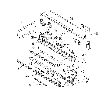
Fig.l is a diagrammatic exploded view of the parts of the
guide rail assembly and the drawer frame, Fig.2 is a
diagrammatic exploded view of the front end of the middle rail
and the cap, Fig.3 is a side view of the middle rail and the
cap prior to assembly, Fig.4 is a sectional view through the
middle rail and the mounted cap and Fig.S is a side view of
the middle rail with mounted cap.
DESCRIPTION OF THE PREFERRED EMBODIMENT
The drawer is formed by the ttao metal draraer frames 28, a
front panel, a bottom plaxe and the back wall 27.
2

Situated inside the drawer frame 28 are three fitting pieces
I6, 17, 18 which are fastened, e.g. welded, to the pull-out
rail 15.
The support rail 2 is fastened in a conventional manner by a
fastening Web 40 to the side wall of the cabi net . The drawer
base rests on a horizontal web 41 of the pull-out rail 15.
Situated in the horizontal web 41 are fir-tenon-shaped tabs
42, which may be pressed out of the horizontal web 41 and into
a groove or the like of the drawer base, e.g. the bottom plate
thereby anchoring the drawer on the pull-out rail 15.
The middle rail 5 is situated between the pull-out rail 15 and
the support rail 2. The middle rail 5 has a bottom profile
5', situated in Which is a carriage 3, in which track rollers
are supported.
The middle rail 5 is therefore guided relative to the support
rail 2 by means of the track rollers supported in the carriage
3.
The middle rail 5 is further provided with a top, partially U-
shaped profile 5". The track rollers 22, 23 supported on the
rear fitting piece 18 of the pull-out rail 15 run along on the
running webs 43, 44 of said profile 5". The running web 45 of
the pull-out rail 15 in turn runs along on the track roller 6
supported on the bottom profile 5' of the middle rail 5.
The middle rail 5 has a front and rear rope pulley 9 for the
control rope 10 which, in the form of a continuous belt, is
supported by means of the rope pulleys 9 on the middle rail 5.
The control rope Z0, which is formed, for example, by a wire
or plastic rope, has a snap-action rope coupling 8. The rope
coupling 8 comprises two coupling parts 12, 13 which are
connected to the ends of the control rope 10.
The coupling part 13 is anchored by means of a hook to the
support rail 2.
3

For connecting the control rope 10 to the pull-out rail 15, a
further coupling is provided. Said coupling comprises an
outer coupling part 19 and an inner coupling part 11. The
outer coupling part 19 is fastened to the pull-out rail 15 by
means of screws or rivets 20, which project through fastening
holes. The outer coupling part 19 embraces the inner coupling
part il in a pincer-like manner. The inner coupling part 11
may be pressed into a trough-like recess 55 of the outer
coupling part 19.
At the front end of the bottom profile 5' of the middle rail
5, a track roller 6 is supported by means of a rivet 7 on lugs
59 of an end bearer 4. The running web 45 of the pull-out
rail 15 runs along on the track roller 6. Two track rollers
22, 23 are mounted by means of rivets 21 on the rearmost
fitting piece 18. The track rollers 22 are guided in the top
profile 5" of the middle rail 5 and axe situated inside the
fitting piece 18. They effect a successive supporting action.
The front track roller 22 is narrower than the rear track
roller 23 and is supported, during displacement of the drawer,
on the web 43 of the top profile 5" of the middle rail 5.
Since the track roller 22 is supported on the bottom
horizontal web 43 and the track roller 23 is supported on the
top horizontal web 44, when the drawer is pulled out or pushed
in there is no change in the direction of rotation of the
track rollers 22, 23 and so the drawer is guided more
smoothly.
As already mentioned, an end bearer 4 made of plastic material
is fastened at the front end of the bottom profile 5' of the
middle rail 5. The end bearer 4 has an opening 62 through
which the track roller 6 projects. The end bearer 4, which
overlaps and with a curved cap 14 at least partially covers
the front end of the bottom profile 5' of the middle rail 5,
is provided with a rail web 63 having a straight portion 63'
4

214~r~1~
and a front, bent-down portion 63".
The end bearer 4 has pins 30, Which are insertable into
punched holes 31 of the middle rail 5 and by means of which
the end bearer 4 may be fitted onto the middle rail 5.
The end bearer 4 is provided with lateral webs 59, into which
may be inserted a rivet 7 serving as a bearing axle for the
track roller 6. The track roller 6 projects into a recess 62
in the end bearer 4.
When the drawer is inserted, the pull-out rails 15 are guided
With their running Webs 45 on the rail web 63 of the end
bearer 4, thereby substantially facilitating insertion of the
drawer into the guide rail assembly.
All three fitting pieces 16, 17, 18 have downwardly projecting
retaining webs 64.
The drawer frames 28 are of a double-walled construction,
having an outer wall 65 and an inner wall 66. At its bottom
edge the outer wall 65 has a retaining Web 67, bent inwards
and upwards in the manner of a hook, by means of which the
outer wall may be hung in the retaining webs 64 of the fitting
pieces 16, 17, 18.
The inner wall 66 has a horizontal web 68, which once the
drawer is assembled rests on the drawer base 38, and a
vertical lateral web 69 which lies laterally adjacent to the
drawer base 38. The transition from the horizontal web 68 to
the inner wall 66 is rounded off.
Since the drawer frame 28 is welded neither to the fitting
pieces 16, 17, 18 nor to the pull-out rail 15, drawer frames
made of any material - ranging from plastic and aluminium
frames to frames made of stainless steel - may be hung in the
fitting pieces 16, 17, 18. The furniture manufacturer is

~m~z~~
therefore offerded the possibility of equipping drawers of
widely differing price with the differential pull-out device
according to the invention.
A pull-in device 1 for the drawer is mounted on the support
rail 2. Said device comprises a spring-loaded tilting segment
121, which serves as a driver for a pin disposed on the middle
rail 5.
6

Representative Drawing
A single figure which represents the drawing illustrating the invention.
Administrative Status

2024-08-01:As part of the Next Generation Patents (NGP) transition, the Canadian Patents Database (CPD) now contains a more detailed Event History, which replicates the Event Log of our new back-office solution.

Please note that "Inactive:" events refers to events no longer in use in our new back-office solution.

For a clearer understanding of the status of the application/patent presented on this page, the site Disclaimer , as well as the definitions for Patent , Event History , Maintenance Fee  and Payment History  should be consulted.

Event History

Description Date
Inactive: IPC expired 2017-01-01
Inactive: IPC from MCD 2006-03-11
Time Limit for Reversal Expired 2004-01-13
Letter Sent 2003-01-13
Grant by Issuance 1999-08-31
Inactive: Cover page published 1999-08-30
Pre-grant 1999-05-21
Inactive: Final fee received 1999-05-21
Amendment Received - Voluntary Amendment 1999-03-25
Letter Sent 1999-03-12
Notice of Allowance is Issued 1999-03-12
Inactive: Approved for allowance (AFA) 1998-07-14
Inactive: Application prosecuted on TS as of Log entry date 1997-12-11
Inactive: Status info is complete as of Log entry date 1997-12-11
All Requirements for Examination Determined Compliant 1995-12-20
Request for Examination Requirements Determined Compliant 1995-12-20
Application Published (Open to Public Inspection) 1995-07-18

Abandonment History

There is no abandonment history.

Maintenance Fee

The last payment was received on 1998-12-29

Note : If the full payment has not been received on or before the date indicated, a further fee may be required which may be one of the following

  • the reinstatement fee;
  • the late payment fee; or
  • additional fee to reverse deemed expiry.

Patent fees are adjusted on the 1st of January every year. The amounts above are the current amounts if received by December 31 of the current year.
Please refer to the CIPO Patent Fees web page to see all current fee amounts.

Fee History

Fee Type Anniversary Year Due Date Paid Date
Request for examination - standard 1995-12-20
MF (application, 3rd anniv.) - standard 03 1998-01-20 1998-01-07
MF (application, 4th anniv.) - standard 04 1999-01-13 1998-12-29
Final fee - standard 1999-05-21
MF (patent, 5th anniv.) - standard 2000-01-13 1999-12-21
MF (patent, 6th anniv.) - standard 2001-01-15 2000-12-28
MF (patent, 7th anniv.) - standard 2002-01-14 2001-12-20
Owners on Record

Note: Records showing the ownership history in alphabetical order.

Current Owners on Record
JULIUS BLUM GESELLSCHAFT M.B.H.
Past Owners on Record
HERMANN HAMMERLE
INGO GASSER
Past Owners that do not appear in the "Owners on Record" listing will appear in other documentation within the application.
Documents

To view selected files, please enter reCAPTCHA code :


To view images, click a link in the Document Description column (Temporarily unavailable). To download the documents, select one or more checkboxes in the first column and then click the "Download Selected in PDF format (Zip Archive)" or the "Download Selected as Single PDF" button.

List of published and non-published patent-specific documents on the CPD .

If you have any difficulty accessing content, you can call the Client Service Centre at 1-866-997-1936 or send them an e-mail at CIPO Client Service Centre.

({010=All Documents, 020=As Filed, 030=As Open to Public Inspection, 040=At Issuance, 050=Examination, 060=Incoming Correspondence, 070=Miscellaneous, 080=Outgoing Correspondence, 090=Payment})


Document
Description 
Date
(yyyy-mm-dd) 
Number of pages   Size of Image (KB) 
Abstract 1995-07-17 1 19
Description 1995-07-17 6 226
Claims 1995-07-17 1 37
Drawings 1995-07-17 3 58
Representative drawing 1998-08-06 1 5
Representative drawing 1999-08-24 1 18
Commissioner's Notice - Application Found Allowable 1999-03-11 1 164
Maintenance Fee Notice 2003-02-09 1 174
Correspondence 1999-05-20 1 31
Fees 1996-12-23 1 59