Sélection de la langue

Search

Sommaire du brevet 2140211 

Énoncé de désistement de responsabilité concernant l'information provenant de tiers

Une partie des informations de ce site Web a été fournie par des sources externes. Le gouvernement du Canada n'assume aucune responsabilité concernant la précision, l'actualité ou la fiabilité des informations fournies par les sources externes. Les utilisateurs qui désirent employer cette information devraient consulter directement la source des informations. Le contenu fourni par les sources externes n'est pas assujetti aux exigences sur les langues officielles, la protection des renseignements personnels et l'accessibilité.

Disponibilité de l'Abrégé et des Revendications

L'apparition de différences dans le texte et l'image des Revendications et de l'Abrégé dépend du moment auquel le document est publié. Les textes des Revendications et de l'Abrégé sont affichés :

  • lorsque la demande peut être examinée par le public;
  • lorsque le brevet est émis (délivrance).
(12) Brevet: (11) CA 2140211
(54) Titre français: GLISSIERE DE TIROIR
(54) Titre anglais: A GUIDE RAIL ASSEMBLY FOR DRAWERS
Statut: Périmé et au-delà du délai pour l’annulation
Données bibliographiques
(51) Classification internationale des brevets (CIB):
(72) Inventeurs :
  • GASSER, INGO (Autriche)
  • HAMMERLE, HERMANN (Autriche)
(73) Titulaires :
  • JULIUS BLUM GESELLSCHAFT M.B.H.
(71) Demandeurs :
  • JULIUS BLUM GESELLSCHAFT M.B.H. (Autriche)
(74) Agent: MARKS & CLERK
(74) Co-agent:
(45) Délivré: 1999-08-31
(22) Date de dépôt: 1995-01-13
(41) Mise à la disponibilité du public: 1995-07-18
Requête d'examen: 1995-12-20
Licence disponible: S.O.
Cédé au domaine public: S.O.
(25) Langue des documents déposés: Anglais

Traité de coopération en matière de brevets (PCT): Non

(30) Données de priorité de la demande:
Numéro de la demande Pays / territoire Date
A 67/94 (Autriche) 1994-01-17

Abrégés

Abrégé anglais


A guide pail assembly for drawers, having a support
rail (2) fastenable to a furniture body a pull-out rail
(15) fastenable to the drawer and a middle rail (5) disposed
between the support rail and the pull-out rail on either side
of the drawer. The weight of the drawers is transmitted
between the rails (2, 5, 15) by means of track rollers (6, 22,
23). A respective deflection roller (9) for a control rope
(10) is disposed at the front and the rear end of the middle
rail (5). Disposed at the front end of the middle rail (5) is
an end bearer (4) made of plastic material, which at the front
has a curved, downwardly directed cap (14) for the front end
of the rail (5).

Revendications

Note : Les revendications sont présentées dans la langue officielle dans laquelle elles ont été soumises.


THE EMBODIMENTS OF THE INVENTION IN WHICH AN EXCLUSIVE
PROPERTY OR PRIVILEGE IS CLAIMED ARE DEFINED AS FOLLOWS:
1. A guide rail assembly for drawers having a support rail
fastenable to a furniture carcass, a pull-out rail
fastenable to the drawer and a middle rail disposed
between the support rail and the pull-out rail on either
side of the drawer, the weight of the drawers being
transmitted between the rails by means of track rollers
and a respective deflection roller preferably being
disposed at the front and the rear end of the middle
rail, and a control rope which is fastened to the
support rail and to the pull-out rail being guided over
the deflection rollers, an end bearer being disposed at
the front end of the middle rail, wherein the end bearer
has at the front a curved, downwardly directed cap for
the front end of the rail, as well as a rail, web which
extends in a longitudinal direction and has a straight
portion and a front, bent-down portion, there being
provided in the region of the rail web an opening, in
which a track roller associated with the middle rail is
supported.
2. A guide rail assembly as claimed in claim 1, wherein the
end bearer (4) has two upwardly projecting lugs which
carry the axle (7) for the track roller (6).
3. A guide rail assembly as claimed in claim 1, wherein the
end bearer is made of plastic material.
7

Description

Note : Les descriptions sont présentées dans la langue officielle dans laquelle elles ont été soumises.

21~~?1~
FIELD AND BACKGROUND OF THE INVENTION
The invention relates to a guide rail assembly for
drawers, having a support rail fastenable to a
furniture carcass, a pull-out rail fastenable to the drawer
and a middle rail disposed between the support rail and the
pull-out rail on either side of the drawer, the weight of the
drawers being transmitted between the rails by means of
track rollers and a respective deflection roller
preferably being disposed at the front and the rear end of the
middle rail, and a control rope which is fastened to the
support rail and to the pull-out rail being guided over the
deflection rollers, an end bearer being disposed at the front
end of the middle rail.
Various guide rai l assemblies for drawers are known, which
enable the entire drawer to be pulled out from the furniture
carcass and yet still be supported by the rails of the
pull-out device. In some cases,
a device is provided which is meant to ensure that
the rails operate differentially in relation to one another.
Said device may, for example, comprise a gear wheel which is
mounted on the middle rail and meshes with toothed racks on
the pull-out rail and the support rail. A simplified
construction would be the arrangement of a friction wheel on
the middle rail.
High-precision guidance of the middle rail is achieved by
means of a control rope which is fastened to the support rail
and the pull-out rail, extends on both sides of the middle
rail and at the front and rear end is guided over belt guides
of the middle rail. Such a differential guide rai l assembly
described in DE-Al-29 04 116.
A guide rai l assembly, in which the control
rope is guided over rollers, is known from US-PS-4,025,138.
1

2~~QZ~~
SUMMARY OF THE INVENTION
The object of the invention is, to provide an improved pull
out guide assembly of the afore-mentioned kind, whereby re-
insertion of a drawer which has been fully withdrawn from the
furniture body is facilitated.
According to the invention, said object is
achieved in that the end bearer
has at the front a curved, downwardly directed cap for the
front end of the rail, as well as a rail web which extends in
a longitudinal direction and has a straight portion and a
front, bent-down portion, there being provided in the region
of the rail web an opening, in Which a track roller associated
with the middle rail is supported.
The end bearer according to the invention facilitates
coupling of the pull-out rail with the middle rail and at the
same time offers protection to the deflection roller for the
control rope which is disposed at the front end of the middle
rail. Insertion of the pull-out rail into the guide rail
assembly is facilitated particularly by the rail webs
disposed in front of and behind the track roller.
BRIEF DESCRIPTION OF THE DRAWINGS
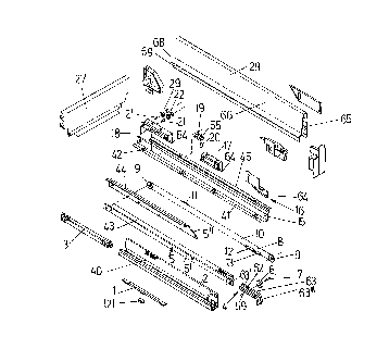
Fig.l is a diagrammatic exploded view of the parts of the
guide rail assembly and the drawer frame, Fig.2 is a
diagrammatic exploded view of the front end of the middle rail
and the cap, Fig.3 is a side view of the middle rail and the
cap prior to assembly, Fig.4 is a sectional view through the
middle rail and the mounted cap and Fig.S is a side view of
the middle rail with mounted cap.
DESCRIPTION OF THE PREFERRED EMBODIMENT
The drawer is formed by the ttao metal draraer frames 28, a
front panel, a bottom plaxe and the back wall 27.
2

Situated inside the drawer frame 28 are three fitting pieces
I6, 17, 18 which are fastened, e.g. welded, to the pull-out
rail 15.
The support rail 2 is fastened in a conventional manner by a
fastening Web 40 to the side wall of the cabi net . The drawer
base rests on a horizontal web 41 of the pull-out rail 15.
Situated in the horizontal web 41 are fir-tenon-shaped tabs
42, which may be pressed out of the horizontal web 41 and into
a groove or the like of the drawer base, e.g. the bottom plate
thereby anchoring the drawer on the pull-out rail 15.
The middle rail 5 is situated between the pull-out rail 15 and
the support rail 2. The middle rail 5 has a bottom profile
5', situated in Which is a carriage 3, in which track rollers
are supported.
The middle rail 5 is therefore guided relative to the support
rail 2 by means of the track rollers supported in the carriage
3.
The middle rail 5 is further provided with a top, partially U-
shaped profile 5". The track rollers 22, 23 supported on the
rear fitting piece 18 of the pull-out rail 15 run along on the
running webs 43, 44 of said profile 5". The running web 45 of
the pull-out rail 15 in turn runs along on the track roller 6
supported on the bottom profile 5' of the middle rail 5.
The middle rail 5 has a front and rear rope pulley 9 for the
control rope 10 which, in the form of a continuous belt, is
supported by means of the rope pulleys 9 on the middle rail 5.
The control rope Z0, which is formed, for example, by a wire
or plastic rope, has a snap-action rope coupling 8. The rope
coupling 8 comprises two coupling parts 12, 13 which are
connected to the ends of the control rope 10.
The coupling part 13 is anchored by means of a hook to the
support rail 2.
3

For connecting the control rope 10 to the pull-out rail 15, a
further coupling is provided. Said coupling comprises an
outer coupling part 19 and an inner coupling part 11. The
outer coupling part 19 is fastened to the pull-out rail 15 by
means of screws or rivets 20, which project through fastening
holes. The outer coupling part 19 embraces the inner coupling
part il in a pincer-like manner. The inner coupling part 11
may be pressed into a trough-like recess 55 of the outer
coupling part 19.
At the front end of the bottom profile 5' of the middle rail
5, a track roller 6 is supported by means of a rivet 7 on lugs
59 of an end bearer 4. The running web 45 of the pull-out
rail 15 runs along on the track roller 6. Two track rollers
22, 23 are mounted by means of rivets 21 on the rearmost
fitting piece 18. The track rollers 22 are guided in the top
profile 5" of the middle rail 5 and axe situated inside the
fitting piece 18. They effect a successive supporting action.
The front track roller 22 is narrower than the rear track
roller 23 and is supported, during displacement of the drawer,
on the web 43 of the top profile 5" of the middle rail 5.
Since the track roller 22 is supported on the bottom
horizontal web 43 and the track roller 23 is supported on the
top horizontal web 44, when the drawer is pulled out or pushed
in there is no change in the direction of rotation of the
track rollers 22, 23 and so the drawer is guided more
smoothly.
As already mentioned, an end bearer 4 made of plastic material
is fastened at the front end of the bottom profile 5' of the
middle rail 5. The end bearer 4 has an opening 62 through
which the track roller 6 projects. The end bearer 4, which
overlaps and with a curved cap 14 at least partially covers
the front end of the bottom profile 5' of the middle rail 5,
is provided with a rail web 63 having a straight portion 63'
4

214~r~1~
and a front, bent-down portion 63".
The end bearer 4 has pins 30, Which are insertable into
punched holes 31 of the middle rail 5 and by means of which
the end bearer 4 may be fitted onto the middle rail 5.
The end bearer 4 is provided with lateral webs 59, into which
may be inserted a rivet 7 serving as a bearing axle for the
track roller 6. The track roller 6 projects into a recess 62
in the end bearer 4.
When the drawer is inserted, the pull-out rails 15 are guided
With their running Webs 45 on the rail web 63 of the end
bearer 4, thereby substantially facilitating insertion of the
drawer into the guide rail assembly.
All three fitting pieces 16, 17, 18 have downwardly projecting
retaining webs 64.
The drawer frames 28 are of a double-walled construction,
having an outer wall 65 and an inner wall 66. At its bottom
edge the outer wall 65 has a retaining Web 67, bent inwards
and upwards in the manner of a hook, by means of which the
outer wall may be hung in the retaining webs 64 of the fitting
pieces 16, 17, 18.
The inner wall 66 has a horizontal web 68, which once the
drawer is assembled rests on the drawer base 38, and a
vertical lateral web 69 which lies laterally adjacent to the
drawer base 38. The transition from the horizontal web 68 to
the inner wall 66 is rounded off.
Since the drawer frame 28 is welded neither to the fitting
pieces 16, 17, 18 nor to the pull-out rail 15, drawer frames
made of any material - ranging from plastic and aluminium
frames to frames made of stainless steel - may be hung in the
fitting pieces 16, 17, 18. The furniture manufacturer is

~m~z~~
therefore offerded the possibility of equipping drawers of
widely differing price with the differential pull-out device
according to the invention.
A pull-in device 1 for the drawer is mounted on the support
rail 2. Said device comprises a spring-loaded tilting segment
121, which serves as a driver for a pin disposed on the middle
rail 5.
6

Dessin représentatif
Une figure unique qui représente un dessin illustrant l'invention.
États administratifs

2024-08-01 : Dans le cadre de la transition vers les Brevets de nouvelle génération (BNG), la base de données sur les brevets canadiens (BDBC) contient désormais un Historique d'événement plus détaillé, qui reproduit le Journal des événements de notre nouvelle solution interne.

Veuillez noter que les événements débutant par « Inactive : » se réfèrent à des événements qui ne sont plus utilisés dans notre nouvelle solution interne.

Pour une meilleure compréhension de l'état de la demande ou brevet qui figure sur cette page, la rubrique Mise en garde , et les descriptions de Brevet , Historique d'événement , Taxes périodiques et Historique des paiements devraient être consultées.

Historique d'événement

Description Date
Inactive : CIB expirée 2017-01-01
Inactive : CIB de MCD 2006-03-11
Le délai pour l'annulation est expiré 2004-01-13
Lettre envoyée 2003-01-13
Accordé par délivrance 1999-08-31
Inactive : Page couverture publiée 1999-08-30
Préoctroi 1999-05-21
Inactive : Taxe finale reçue 1999-05-21
Modification reçue - modification volontaire 1999-03-25
Lettre envoyée 1999-03-12
Un avis d'acceptation est envoyé 1999-03-12
Inactive : Approuvée aux fins d'acceptation (AFA) 1998-07-14
Inactive : Dem. traitée sur TS dès date d'ent. journal 1997-12-11
Inactive : Renseign. sur l'état - Complets dès date d'ent. journ. 1997-12-11
Toutes les exigences pour l'examen - jugée conforme 1995-12-20
Exigences pour une requête d'examen - jugée conforme 1995-12-20
Demande publiée (accessible au public) 1995-07-18

Historique d'abandonnement

Il n'y a pas d'historique d'abandonnement

Taxes périodiques

Le dernier paiement a été reçu le 1998-12-29

Avis : Si le paiement en totalité n'a pas été reçu au plus tard à la date indiquée, une taxe supplémentaire peut être imposée, soit une des taxes suivantes :

  • taxe de rétablissement ;
  • taxe pour paiement en souffrance ; ou
  • taxe additionnelle pour le renversement d'une péremption réputée.

Les taxes sur les brevets sont ajustées au 1er janvier de chaque année. Les montants ci-dessus sont les montants actuels s'ils sont reçus au plus tard le 31 décembre de l'année en cours.
Veuillez vous référer à la page web des taxes sur les brevets de l'OPIC pour voir tous les montants actuels des taxes.

Historique des taxes

Type de taxes Anniversaire Échéance Date payée
Requête d'examen - générale 1995-12-20
TM (demande, 3e anniv.) - générale 03 1998-01-20 1998-01-07
TM (demande, 4e anniv.) - générale 04 1999-01-13 1998-12-29
Taxe finale - générale 1999-05-21
TM (brevet, 5e anniv.) - générale 2000-01-13 1999-12-21
TM (brevet, 6e anniv.) - générale 2001-01-15 2000-12-28
TM (brevet, 7e anniv.) - générale 2002-01-14 2001-12-20
Titulaires au dossier

Les titulaires actuels et antérieures au dossier sont affichés en ordre alphabétique.

Titulaires actuels au dossier
JULIUS BLUM GESELLSCHAFT M.B.H.
Titulaires antérieures au dossier
HERMANN HAMMERLE
INGO GASSER
Les propriétaires antérieurs qui ne figurent pas dans la liste des « Propriétaires au dossier » apparaîtront dans d'autres documents au dossier.
Documents

Pour visionner les fichiers sélectionnés, entrer le code reCAPTCHA :


Pour visualiser une image, cliquer sur un lien dans la colonne description du document (Temporairement non-disponible). Pour télécharger l'image (les images), cliquer l'une ou plusieurs cases à cocher dans la première colonne et ensuite cliquer sur le bouton "Télécharger sélection en format PDF (archive Zip)" ou le bouton "Télécharger sélection (en un fichier PDF fusionné)".

Liste des documents de brevet publiés et non publiés sur la BDBC .

Si vous avez des difficultés à accéder au contenu, veuillez communiquer avec le Centre de services à la clientèle au 1-866-997-1936, ou envoyer un courriel au Centre de service à la clientèle de l'OPIC.

({010=Tous les documents, 020=Au moment du dépôt, 030=Au moment de la mise à la disponibilité du public, 040=À la délivrance, 050=Examen, 060=Correspondance reçue, 070=Divers, 080=Correspondance envoyée, 090=Paiement})


Description du
Document 
Date
(aaaa-mm-jj) 
Nombre de pages   Taille de l'image (Ko) 
Abrégé 1995-07-17 1 19
Description 1995-07-17 6 226
Revendications 1995-07-17 1 37
Dessins 1995-07-17 3 58
Dessin représentatif 1998-08-06 1 5
Dessin représentatif 1999-08-24 1 18
Avis du commissaire - Demande jugée acceptable 1999-03-11 1 164
Avis concernant la taxe de maintien 2003-02-09 1 174
Correspondance 1999-05-20 1 31
Taxes 1996-12-23 1 59