Note: Descriptions are shown in the official language in which they were submitted.
CA 02140392 2004-08-20
INTEGRATED TELEPHONE AND CABLE COMMUNICATION NETWORKS
FIELD OF THE INVENTION
The present invention relates to telecommunications
generally and more particularly to combination telephone and
cable networks.
BACKGROUND OF THE INVENTION
In recent years, integration of cable television and
telephone networks has shifted from being a theoretical
possibility to being a commercial reality. Business entities now
exist which operate both telephone and cable networks.
Various suggestions for integration of cable television
and telephone networks appear in the literature. Examples of
relevant articles are listed hereinbelow:
Laws of Convergence: Impacting cable's future,
International Cable, March 1993; pp. 42 - 45;
Cable telecom UR, International Cable, March 1993; pp.
46 - 51;
Cable/telephony possibilities, International Cable,
March 1993; pp. 52 ff.
Telecommunications, IEEE Spectrum, January 1993;
pp. 38 - 41.
U.S. Patent 5,027,426 to Chiocca, Jr. describes a
signal coupling apparatus for combining CATV and telephone
signals onto a single cable for transmission to an impulse pay-
per-view converter device.
1
CA 02140392 2004-03-18
SUMMARY OF THE INVENTION
The present invention seeks to provide an integrated
cable and telephone network and associated apparatus which
greatly expands flexibility and utilization efficiency of
existing infrastructure.
There is provided in accordance with one aspect of the
present invention a subscriber interface unit for interfacing
between a subscriber telephone facility and a subscriber cable
facility on one side and first and second network cabling
connected respectively to a telephone network and a cable
network on the other hand and including apparatus for providing
communication between the subscriber telephone facility and the
second network cabling and between the subscriber cable facility
and the first network cabling.
The apparatus includes:
a cable signal receiver and tuner for receiving and
tuning a cable communication signal which comprises at least one
of a video signal, an audio signal, a voice signal and a data
signal;
video and audio converters for converting at least part
of the video and audio signals to a format suitable for
receiving at a television receiver and for supplying the
converted video and audio signals to the television receiver;
a voice converter for converting at least part of the
voice signal to a format suitable for transmission over a
telephone link and for supplying the converted voice signal to
at least part of the telephone network;
a data converter for converting at least part of the
data signal to a format suitable for transmission over either of
a cable link or the telephone link and for supplying the
converted data signal to at least one of the cable link and the
telephone link;
2
CA 02140392 2004-03-18
a cable signal transmitter for transmitting at least
part of a cable converted signal over the cable link; and
a telephone signal converter for converting a telephone
communication signal which comprises at least one of a video
signal, an audio signal, a voice signal and a data signal, to a
signal suitable for transmission on either of the cable link or
-.=he telephone link.
In accordance with a preferred embodiment of the
present invention the subscriber interface unit includes
directing apparatus for directing information between the first
subscriber cabling on one side and either of the first and second
network cabling on the other side.
Further in accordance with a preferred embodiment of
the present invention the subscriber interface unit includes
directing apparatus for directing information between the second
subscriber cabling on one side and either of the first and second
network cabling on the other side.
Additionally in accordance with a preferred embodiment
of the present invention the subscriber interface unit includes
directing apparatus for directing information between the first
network cabling on one side and either of the first and second
subscriber facilities on the other side.
Still further in accordance with a preferred embodiment
of the present invention the subscriber interface unit includes
directing apparatus for directing information between the second
network cabling on one side and either of the first and second
subscriber facilities on the other side.
Additionally in accordance with a preferred embodiment
cthe present invention the subscriber interface unit include
3
2i4~39
apparatus for automatic load directing between the first and
second network cabling.
Further in accordance with a preferred embodiment of
the present invention, the subscriber interface unit includes
reformatting apparatus for changing information from a cable
network format to a telephone network format.
Additionally in accordance with a preferred embodiment
of the present invention, the subscriber interface unit includes
reformatting apparatus for changing information from a telephone
network format to a cable network format.
In an analog signal environment, the reformatting
apparatus comprises demodulation apparatus. In a digital signal
environment the reformatting apparatus comprises a digital cable
transmitter.
In accordance with a preferred embodiment of the
invention at least one of the first subscriber cabling and the
first network cabling comprises twisted pair cabling.
In accordance with a preferred embodiment of the
invention at least one of the second subscriber cabling and the
second network cabling comprises coaxial cabling.
4
~1~~3~~
BRIEF DESCRIPTION OF THE DRAWINGS
The present invention will be understood and
appreciated more fully from the following detailed description,
taken in conjunction with the drawings in which:
Fig. 1 is a generalized block diagram illustration of
an integrated telephone and cable network system constructed and
operative in accordance with a preferred embodiment of the
present invention;
Fig. 2 is a generalized block diagram illustration of
a portion of the integrated telephone and cable network system of
Fig. 1 in accordance with one preferred embodiment of the
invention;
Fig. 3 is a generalized block diagram illustration of a
portion of the integrated telephone and cable network system of
Fig. 1 in accordance with another preferred embodiment of the
invention;
Fig. 4 is a generalized block diagram illustration of
a portion of the integrated telephone and cable network system of
Fig. 1 in accordance with yet another preferred embodiment of the
invention;
Fig. 5 is a generalized block diagram of circuitry
useful in the apparatus of Figs. 1 - 4 which is constructed in
accordance with one embodiment of the present invention;
Fig. 6 is a generalized block diagram of circuitry
useful in the apparatus of Figs. 1 - 4 which is constructed in
accordance with another embodiment of the present invention;
Fig. 7 is a generalized block diagram of a CATV system
2~4~3~2
employing at least part of the system of Figs. 1 - 6; and
Fig. 8 is a block diagram of circuitry useful in the
apparatus of Fig. 7.
6
~~~0392
DETAILED DESCRIPTION OF PREFERRED EMBODIMENTS
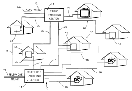
Reference is now made to Fig. 1 which illustrates an
integrated telephone and cable network constructed and operative
in accordance with a preferred embodiment of the present
invention and including a telephone network, indicated generally
by reference numeral 10 and a cable network, indicated generally
by reference numeral 12.
The telephone network 10 preferably includes at least
one directing center 14 and first network cabling 16 connecting
the directing center to a multiplicity of subscribers. The cable
network preferably includes at least one headend or cable
directing center 18, both referred to throughout as a cable
directing center, and second network cabling 20 connecting the
cable directing center to a multiplicity of subscribers.
Both the telephone network and the cable network may be
connected by communication links 22 and 24 respectively to remote
networks, both cable and telephone. The telephone network cabling
may be twisted pair, fiber optic or any other suitable
conventional cabling and the cable network cabling may be
coaxial, fiber optic or any other suitable conventional cabling.
The present invention concerns subscribers, here
designated by reference numeral 30, who are connected to both the
conventional telephone and cable networks. Each such subscriber
is equipped with a subscriber telephone facility including first
subscriber cabling and at least one telephone appliance and with
a subscriber cable facility including second subscriber cabling
7
~~~U392
and at least one cable appliance.
In accordance with a preferred embodiment of the
present invention, there is provided at each subscriber location
a subscriber interface unit 32 interfacing between the subscriber
telephone facility and the subscriber cable facility thus
enabling communication between a telephone appliance and a cable
appliance at the subscriber location via either or both the first
and second subscriber cabling and between a conventional
telephone network and a conventional cable network and either or
both of a telephone appliance and a cable appliance in the
subscriber location.
The sections of the subscriber cabling, whether part of
the telephone network or part of the cable network, which extend
outside the subscriber location and are linked to the subscriber
interface unit 32 are referred to hereinafter as external cabling
or external links, whereas the sections of the. subscriber
cabling, whether part of the telephone network or part of the
cable network, which extend throughout the subscriber location
and are linked to the subscriber interface unit 32 are referred
to hereinafter as internal cabling or internal links.
In accordance with a preferred embodiment of the
present invention external links are employed to convey
communication signals to and from the subscriber location via
subscriber interface unit 32 whereas internal links are employed
to convey communication signals in the subscriber location
to different appliances, between appliances and from appliances
to remote communication networks via subscriber interface unit
8
_~~~~3~~
32.
The subscriber interface unit 32 may be operative in
various operating environments at the subscriber location. One
such environment is illustrated generally in Fig. 2, wherein the
subscriber interface unit is embodied in a server 40 which is
coupled to the first and second network cabling 16 and 20 and is
also connected to a plurality of computers or terminals 42 via a
local area network 44. It is noted that one or more of the
plurality of computers or terminals 42 may also be connected
directly to either or both of the first and second network
cabling 16 and 20 via suitable modems or other interfaces (not
shown) or via extension cards which are added to the computers or
terminals 42 each of which includes a subscriber interface unit
32. It is to be appreciated that network 44 may also be a
personal area network or a wide area network.
Another such environment is illustrated generally in
Fig. 3, wherein the subscriber interface unit is embodied in a
CATV converter 50 which is coupled to the first and second
network cabling 16 and 20 and is also connected to various
communications appliances and devices, such as a television 52, a
facsimile machine 54, a telephone 56, a computer 58 and a
communicating utility meter 60. The connections to the various
communications appliances and devices may be via either cable
wiring 62 or telephone wiring 64 , independent of the medium,
i.e. first or second network cabling 16 and 20, along which the
communication is carried from the subscriber location to a remote
location and from the remote location to the subscriber.
A further such environment is illustrated generally in
9
~I~Q392
Fig. 4, wherein the subscriber interface unit is embodied in a
network server and subscriber switching unit 70 which is coupled
to the first and second network cabling 16 and 20 and is also
connected to various communications networks, appliances and
devices, such as a computer terminal 72, a local cable TV network
74, a local computer network 76, a PABX based internal telephone
network 78, an individual telephone 80, a facsimile machine 82, a
a communicating utility meter or network 84, and a television 86.
The connections to the various communications
appliances and devices may be via either cable wiring or
telephone wiring, independent of the medium, i.e. first or
second network cabling 16 and 20, along which the communication
is carried from the subscriber location to a remote location and
from the remote location to the subscriber.
The subscriber unit may thus be seen to be operative
for interfacing between a subscriber telephone facility and a
subscriber cable facility on one side and first and second
network cabling connected respectively to a telephone network and
a cable network on the other hand and to include apparatus for
providing communication between the subscriber telephone
facility and the second network cabling and between the
subscriber cable facility and the first network cabling.
In accordance with a preferred embodiment of the
present invention the subscriber interface unit includes
directing apparatus for directing information between the first
subscriber cabling on one side and either of the first and second
network cabling on the other side.
~~40392
Further in accordance with a preferred embodiment of
the present invention the subscriber interface unit includes
directing apparatus for directing information between the second
subscriber cabling on one side and either of the first and second
network cabling on the other side.
Additionally in accordance with a preferred embodiment
of the present invention the subscriber interface unit includes
directing apparatus for directing information between the first
network cabling on one side and either of the first and second
subscriber facilities on the other side.
Still further in accordance with a preferred embodiment
of the present invention the subscriber interface unit includes
directing apparatus for directing information between the second
network cabling on one side and either of the first and second
subscriber facilities on the other side.
Additionally in accordance with a preferred- embodiment
of the present invention the subscriber interface unit includes
apparatus for automatic load directing between the first and
second network cabling.
Further in accordance with a preferred embodiment of
the present invention, the subscriber interface unit includes
reformatting apparatus for changing information from a cable
network format to a telephone network format.
Additionally in accordance with a preferred embodiment
of the present invention, the subscriber interface unit includes
reformatting apparatus for changing information from a telephone
network format to a cable network format.
11
zz4o392
The foregoing features are provided in a preferred
embodiment of a subscriber interface unit which is illustrated in
Fig. S. Subscriber interface unit 32 comprises a tuner 100 which
receives video, audio, and data from a cable information source
which forms part of an external cable network 102 via cabling 20
and communication port 151. The data received may include
graphics, pictures, facsimile, E-mail, voice-mail, speech in the
form of telephone conversations and all types of digital computer
generated data.
The cable source may be, for example, a cable
transmitting facility or a satellite communication source.
The tuner 100 preferably includes all circuitry
required for receiving, tuning, filtering and amplification of
the signal supplied by the cable source. The signal is then
detected and separated by one or more of the following detectors:
a voice data detector 108, a video detector 110, an audio
detector 112 and a data detector 114.
The output of the voice data detector 108 is provided
to a telephone signal modulator 121 which is operative to
transmit voice signals received along external cable link 20
directly to an internal telephone network 130.
The output of video detector 110, typically in the form
of a composite video baseband signal, is provided to a video
bandpass trap filter 116, which provides a "clean" composite
video baseband signal to an external television (TV) or a
multimedia output device or network where it may be displayed,
stored or edited.
The output of audio detector 112, in the form of an
12
_~~~0392
audio signal, is provided to an audio bandpass trap filter 118
which provides a "clean" audio signal to an external television
(TV) receiver, audio output device or entertainment system or
network where it may be played, stored or edited.
The data output from data detector 114 is provided to a
data packet multiplexer/demultiplexer (mux/demux) 120 which
directs the data according to its destination.
Data packet mux/demux 120 preferably communicates via a
micro-processor bus 122 for transmission of data which is to be
displayed on a computer terminal such as terminal 72 (Fig. 4).
Alternatively or additionally bus 122 may be a mini-computer bus
or any other computer communication bus. In a preferred
embodiment of the invention bus 122 is the communication bus of a
personal computer such as the AT-Bus or the EISA Bus.
Compressed images received via mux/demux 120 or from
an external image source (not shown) are provided to a JPEG or
other suitable compressor/decompressor unit 124 where they are
decompressed and transmitted to the micro-processor bus 122, if
they are to be displayed on a computer monitor, or to an on-
screen-display (OSD) unit 126 which prepares the images for
display on a TV screen.
It is to be appreciated that the
compressor/decompressor unit 124 may be a unit which is separate
and apart from the remainder of the subscriber interface unit 32.
In such a case, subscriber interface unit 32 communicates with
compressor/decompressor unit 124 whenever compression or
decompression is required.
13
_21~~392
OSD unit 126 may receive uncompressed image data
directly from mux/demux 120. Data received via mux/demux 120 may
also be fed directly or via the compressor/decompressor unit 124
to a serial port interface 128, such as an RS-232C, which can
communicate with terminals, modems and external storage devices.
In a preferred embodiment of the present invention
mux/demux 120 may also output directly to the telephone signal
modulator 121 which is operative to transmit voice signals
received along external cable link 20 directly to the internal
telephone network 130.
If the data from the data packet mux/demux 120 is to be
further communicated over telephone links, or to telephonic
interfaces, data packet mux/demux 120 outputs it to a telephonic
fax-modem or modem unit 127. Telephonic fax-modem unit 127
prepares the data in a suitable format for transmission as
facsimile or plain data over telephone links, decompresses it if
it was compressed, for example in facsimile communication, and
preforms the required modulation operations if the data is to be
transmitted to telephone networks. Fax-modem unit 127 then
provides it to one or more of the following: an internal
telephone network 130 via a communication port 157, serial port
interface 128 and micro-processor bus 122.
It is to be appreciated that the telephonic fax-modem
unit 127 may be a unit which is separate and apart from the
remainder of the, subscriber interface unit 32. In such a case,
subscriber interface unit 32 includes an additional
communication port (not shown) which is connected to a port of
the telephonic fax-modem unit 127 by a communication cable (not
14
z~.~03~2
shown).
The subscriber interface unit 32 also receives
information via an external telephone network 106 and a
communication port 153. The speech and non-data information
received from the external network is transmitted directly to
internal telephone network 130. Facsimile data and plain data
received from the external telephone network 106 is supplied to
the telephonic fax-modem unit 127. Fax modem unit 127 is
operative to supply information received via the external
telephone network 106 to a fax/data/voice combiner 132. The
output of combiner 132 is supplied to an RF modulator 134 which
receives a carrier input from a cable carrier source (not shown)
and outputs via an amplifier 136 to an internal cable link 138
via communication port 155.
Fax modem unit 127 is also operative to interface with
OSD unit 126 to enable information received via the external
telephone network 106 to be displayed on a television receiver.
Alternatively or additionally fax modem unit 127 may receive
information from the OSD unit 126 and transmit that information
to internal telephone network 130.
Fax modem unit 127 is additionally operative to
interface with serial port interface 128 such as an RS-232C and
with micro-processor bus 122 for transmitting computer generated
data over cable or telephone links.
Additionally in accordance with a preferred embodiment
of the present invention, fax modem unit 127 may interface with
an encryptor and a decrypter (not shown) for providing encrypted
Z.~~~392
communications .
The functionality of the subscriber interface unit 32
for communications received via an external cable link 20 and via
an external telephone link 16 has been described hereinabove. It
is also a particular feature of the present invention that the
subscriber interface unit 32 is operative for directing
communications received via internal cable link 138 and via an
internal telephone network 130 to either the cable information
source 102 or the external telephone network 106. The apparatus
carrying out these functionalities will now be described:
The subscriber interface unit 32 also receives
information via internal cable link 138 and via
compressor/decompressor 124 to the extent that compression or
decompression is required and thence directly to external cable
link 20. Alternatively or additionally this information may also
be fed to a television receiver via the above-described
information pathway beginning with tuner 100 in the same way as
information received via cable link 20 passes. It is to be
appreciated that data may be directed via mux/demux 120 and fax
modem unit 127 to either external telephone network 106 or
internal telephone network 130, as described hereinabove.
The subscriber interface unit 32 additionally receives
information from internal telephone network 130 and transmits
voice and non-data information directly to the external telephone
network 106. Additionally, data is transmitted via fax modem unit
127 directly to the external telephone network 106 or via
combiner 132 and modulator 134 to either internal cable link 138
or external cable link 20. Compression and decompression as
16
necessary is provided by compressor/decompressor 124.
The apparatus of Fig. 5 is particularly suited for use
with analog video and audio signals and digital information
carried thereby.
Reference is now made to Fig. 6, which illustrates a
subscriber interface unit 180 which is particularly suited for
use with purely digital signals which include inter alia digital
video and digital audio information as well as data.
The subscriber interface unit 180 comprises a digital
cable interface 200, such as a QPSK modulator/demodulator, which
receives digital information from cable information source,
which forms part of an external cable network 102 via a
communication port 251 and via external cable link 20. The output
of digital cable interface 200 is supplied to a digital
multiplexer/demultiplexer (mux/demux) 202, preferably a TDM
multiplexer/demultiplexer, which separates the information into
voice, video, audio and data information. The video and audio
information is supplied to compressor/decompressor 204,
preferably an MPEG compressor/decompressor, which provides all
necessary compression and decompression and outputs video
information via a digital to analog (D/A) converter 206 and which
outputs audio information via a D/A converter 208 to a
television receiver (not shown).
The voice information is supplied to a telephone signal
interface unit 210, which converts the digital data to an analog
voice signal suitable for transmission over telephone links and
provides it to either of internal telephone network 212 or to
17
_~1~~392
external telephone link 16.
Facsimile information in conventional facsimile format
and some other data information is supplied to a fax modem unit
214, which may be identical to fax modem unit 127 (Fig. 5). The
fax modem unit 214 outputs via a fax/data/voice combiner 216 and
a digital cable transmitter unit 218, which prepares the digital
data in a format suitable for transmission over digital cable
links. Digital cable transmitter 218 may also receive data
information directly from mux/demux 202. The output of digital
cable transmitter 218 is supplied to cable link 222 via
a communication port 255.
Compressed data is supplied by mux/demux 202 to a
compressor/decompressor 224, such as a JPEG
compressor/decompressor. Compressor/decompressor 224 may be
identical to compressor/decompressor 124 (Fig. 5) and is
operative to decompress and transmit the data to a micro-
processor bus 226, if it is to be displayed on a computer
monitor, or to an on-screen-display (OSD) unit 228 which prepares
images for display on a TV screen. The OSD unit 228 may also
receive uncompressed image data directly from mux/demux 202. Data
received via mux/demux 202 may also be fed directly or via the
compressor/decompressor unit 224 to a serial port interface 230,
such as an RS-232C, which can typically communicate with modems
and terminals. The output of compressor/decompressor 224 may also
be supplied via digital cable transmitter 218 to cable link 222.
Compressor/decompressor unit 224 may be also operable to receive
images from an image source (not shown).
The subscriber interface unit 180 also receives
18
2~~~~92
information via an external telephone network 201 and a
communication port 253 and transmits speech and non-data
information directly to internal telephone network 212. Fax modem
unit 214 is also operative to transmit information received via
the external telephone network to fax/data/voice combiner 216.
The output of combiner 216 is supplied via digital cable
transmitter 218 and via a communication port 255 to internal
cable link 222.
Fax modem unit 214 is also operative to interface with
OSD unit 228 to enable information received via the external
telephone network to be displayed on a television receiver.
Alternatively or additionally fax modem unit 214 may receive
information from the OSD unit 228 and transmit that information
to internal telephone network 212 via a communication port 257,
such as for videophone applications.
Fax modem unit 214 is additionally operative to
interface with serial port interface 230 and with microprocessor
bus 226 for transmitting computer generated data over cable or
telephone links.
Additionally in accordance with a preferred embodiment
of the present invention, fax modem unit 214 may interface with
an encryptor and a decrypter (not shown) for providing encrypted
communications.
The functionality of the subscriber interface unit 180
of Fig. 6 for communications received via an external cable link
20 and via an external telephone link 16 has been described
hereinabove. It is also a particular feature of the present
19
21~~3~~
invention that the subscriber interface unit 180 is operative for
directing communications received via internal cable link 138 and
via an internal telephone network 130 to either the external
cable network 102 or the external telephone network 201. The
apparatus carrying out these functionalities will now be
described:
The subscriber interface unit 180 also receives
information from internal cable link 222 via
compressor/decompressor 204 or compressor/decompressor 224 to the
extent that compression or decompression is required and thence
directly to external cable link 20. Alternatively or additionally
this information may also be fed to a television receiver via the
above-described information pathway beginning with digital cable
interface 200 in the same way as information received via cable
link 20.
It is to be appreciated that the
compressor/decompressor units 204 and 224 may be units which are
separate and apart from the remainder of the subscriber interface
unit 180. In such a case, subscriber interface unit 180
communicates with compressor/decompressor units 204 and 224
whenever compression or decompression is required.
Data may be also directed via mux/demux 202 and fax
modem unit 214 to either external telephone network 201 or
internal telephone network 212, as described hereinabove.
The subscriber interface unit 180 additionally receives
information from internal telephone network 212 and transmits
voice information directly to the external telephone network 201.
Additionally, data is transmitted via fax modem unit 214 directly
~1~~~~~
to the external telephone network 201 or via combiner 216 and
modulator 218 to either internal cable link 222 or external
cable link 20. Compression and decompression as necessary is
provided by compressor/decompressor 204 or
compressor/decompressor 224.
It is to be appreciated that if the cabling_is similar
for the telephone and cable networks, for example in the case
that all cabling is fiber optic cabling, then the conversion from
telephone to cable and vice versa is much simpler and part of the
units described in Figs. 5 and 6 may be simplified or even
eliminated. For example, digital cable interface 200 and digital
cable transmitter 218 may become an interface unit which performs
both interface and transmission operations.
Reference is now made to Fig. 7, which is a generalized
block diagram illustration of a CATV system constructed and
operative in accordance with another preferred embodiment of the
present invention and employing at least part of the systems of
Figs. 1 - 6.
The CATV system includes or is used with a CATV
network 310 which is typically a combination telephone - radio
frequency (RF) network. The network employs RF links, such as
cable links 20 (Fig. 1) which may be connected to a headend via
trunk cables, wireless radio communications and/or satellite
communications for transmitting information to subscribers and
employs an existing telephone network, such as network 10 having
telephone links 16 (Fig. 1) for receiving information from
subscribers. Alternatively the transmission to the subscriber
21
21~U392
may be via a telephone link and the transmission from the
subscriber may be via a cable, wireless or satellite link.
According to further alternatives, communication in both
directions may be by telephone or by cable, wireless or
satellite link.
The CATV network preferably comprises a program
transmitter 311 coupled through a satellite communication link
312 with a multiplicity of subscriber units 314. Alternatively,
communication link 312 may be either a cable or a fiber-optic
communication link.
Preferably, each of the multiplicity of subscriber
units includes a television 316, a CATV interface unit 318
preferably having associated therewith a subscriber interface
unit 319 such as subscriber interface units 32 (Fig. 5) and 180
(Fig. 6).
The CATV interface unit 318 may include a conventional
CATV converter which is commercially available from multiple
vendors.
CATV interface units 318 may be connected, via
subscriber interface unit 319, to a standard telephone network
324 and to a cable network 325 for voice, data and fax
communications. It is to be appreciated that cable network 325
may be a satellite communication network including a satellite
link such as satellite link 312.
Conventional CATV data such as authorizations and
program viewing data is communicated to and from a subscriber
management system 326 via either the telephone network 324 or the
cable network 325. Facsimile, E-mail, voice-mail and mail data
22
- ~~~t~~~
may be provided to the subscriber units 314 via the CATV network
from an information generator 327, such as a standard fax machine
328, a computer and associated modem 329 and a computer and
associated cable interface 331.
In a preferred embodiment of the invention the CATV
interface unit 318 may be also associated with a keyboard 330 to
produce faxes to be sent to any of fax machines, internal fax-
modem cards and cable interface cards forming part of computer
systems via the CATV network.
Reference is now made to Fig. 8 which is a generalized
block diagram illustration of CATV interface unit 318 which forms
part of subscriber unit 314.
CATV interface unit 318 receives facsimile and other
data and voice as well as communication management data from
telephone network 324 (Fig. 7), forming part of CATV network 310,
via a receive-transmit subscriber interface unit 350 such as unit
32 or unit 180 as described hereinabove with reference to Figs. 5
and 6 respectively via a standard telephone link 352. CATV
interface unit 318 also receives facsimile and other data and
voice as well as communication management data from a cable
network 325 via a conventional coaxial cable or fiber optic link
353.
Unit 350 provides data to a processor 356 via a
communication bus interface 354. Processor 356 provides facsimile
data and other data as well as voice to either of an internal
memory unit 358 or an external memory module 360 via a memory
controller 362. Preferably, external memory unit 360 includes a
23
~~~0~92
memory card 361 and a memory card reader (not shown).
In a preferred embodiment of the invention processor
356 also receives data input by a subscriber via keyboard 330
(Fig. 7) and prepares it in a suitable format for transmission as
fax, E-mail or mail data via telephone link 352 or cable link
353. Processor 356 may also provide fax data, E-mail data, voice-
mail data and mail data to hard copy output unit 332 for
printout.
In many cases unit 350 already includes a
compression/decompression standard unit for facsimile
transmission and reception. If the fax data is not compressed at
unit 350 it may be necessary to compress it before storage in the
memory. In that case a compression/decompression unit which is
used for conventional CATV digital video and audio transmissions
may be employed, so that processor 356 provides the fax, E-mail,
voice-mail and mail data to either of internal memory unit 358 or
external memory module 360 via compression/decompression unit
364, preferably in the MPEG format, and via memory controller
362.
Stored faxes, E-mail, voice-mail and other data are
provided by either of the memories 358 or 360 to processor 356
via memory controller 362 and, in the case that the data was
previously compressed by compression/decompression unit 364, via
unit 364. The stored data is then provided to an on-screen-
display (OSD) unit 366. OSD unit 366 prepares the fax data, the
E-mail data, the voice-mail data and other data in a format
suitable for reception by a TV receiver and provides it to CATV
tuner and receiver unit 368. In a preferred embodiment of the
24
2~.~(3~c~~
invention OSD unit 366 may be part of the CATV tuner and receiver
unit 368.
CATV tuner and receiver unit 368 also receives
encrypted video and audio program transmissions from
communication link 312 and provides decrypted video and audio
data to TV 316. CATV tuner and receiver unit 368 is operable upon
authorizations received from subscriber management system 326
which may be received either via satellite or via any of
telephone link 352 and cable link 353 and processed in processor
356 or in CATV tuner and receiver unit 368.
Upon tuning the television receiver to an information
display channel, such as a fax display channel or upon selection
of a non-CATV data display option on a CATV remote control unit
when the television receiver is tuned to any channel, CATV tuner
and receiver unit 368 displays on the television receiver menus
of potential data selections. Upon selection of a preferred menu,
images of stored information, such as faxes, together with audio
from communication link 312 or voice-mail, which accompanies the
received information are displayed on the TV receiver 316. The
audio from link 312 may alternatively be any suitable background
music.
At any time, prior to, during or after display of the
information on the TV, a hard copy thereof may be provided by
hard copy output device 332.
It is to be appreciated that the system of the present
invention may be also employed in a videophone system in which
the images of the people involved in a telephone conversation are
~1~U392
displayed on the television screen. When a connection is made the
telephone number and the image of the person originating the call
are displayed on the television screen of the recipient,
preferably at a corner of the television screen. Thus, the video
telephone conversation may take place simultaneously with a video
program display.
The combined telephone and cable network of the present
invention also enables switching of information between the cable
network and the telephone network in case one of the networks is
overloaded. In such a case functions such as meter reading over
communication networks can be constantly maintained by routing
communication from telephone to cable and vice versa.
It will be appreciated by persons skilled in the art
that the present invention is not limited by what has been
particularly shown and described hereinabove. Rather the scope of
the present invention is defined only by the claims which follow:
26