Note: Descriptions are shown in the official language in which they were submitted.
FIELD OF THE INVENTION
The present invention relates generally to a control
stand for a locomotive or other railway transit vehicle, and more
particularly to a new and improved apparatus for determining the
position of a throttle, dynamic brake and/or reverser control
handle on a locomotive control stand, using an optical encoder
at or near its limit of sensitivity and resolution to provide a
more positive determination of the handle~s pivotal position.
CROSS REFERENCE TO RELATED APPLICATIONS
10The invention taught in this patent application is
closely related to the inventions taught in the following co-
pending commonly owned Canadian applications: 2,140,109;
2,140,110; 2,140,111; 2,140,112; and 2,140,113 all filed January
12, 1995; 2,140,398; 2,140,399; and 2,140,400 all filed
15January 17, 1995; 2,141,087 filed January 25, 1995; and 2,148,867
filed May 8, 1995.
Sg/,iJ
BACKGROUND OF THE INVENTION
In railroad locomotive operations, the throttle,
dynamic brake and reverser actions of the locomotive, locomotives
or other drive units, are controlled by the operator or engineer
in the cab of the lead unit by manipulating three handles
extending from the control stand, one handle each for throttle,
dynamic brake, and reverser. The throttle handle, of course,
controls the development of the tractive effort of the
locomotive; i.e. the diesel engines or other power units. The
dynamic brake handle controls the development of a retarding
force known as dynamic brake, for example the electric motors
driving the locomotive wheels, to place them in either motor mode
where they will drive the wheels, or in generator mode, where
they will function as a retarding force. The reverser handle
controls the forward and reverse rotation of the electric motors
to selectively drive the train forward or rearward, and includes
a neutral position. Pursuant to current practice, the control
stand
sgl~ 2
- 2140~01
is designed to be a man-to-machine interface and ideally is
strictly an electronic/electric device having no direct mechanical,
hydraulic or pneumatic connections the devices controlled.
Instead, encoding means are preferably provided within the control
stand to read and interpret the positions of the three handles, and
convey appropriate signals, indicative of such positions, to an
associated microcomputer. The associated microcomputer is
programmed to interpret the encoded signals regarding the positions
of the throttle, dynamic brake and reverser handles, as positioned
at the control stand, and then electronically issue corresponding
commands to manipulate the devices intended within the locomotive
or locomotives. When utilizing a microcomputer, the throttle,
dynamic brake and reverser commands effected at the control stand,
are dependent upon the given angular positions of the three control
handles, which are normally sensed and monitored by rotary encoding
devices, which are mechanically coupled to associated rotary axles
to which the control handles are secured, utilizing cams to actuate
microswitches or contacts to provide a signal to the microcomputer
as noted above. Such mechanical devices leave a lot to be desired,
in that they do not provide the exacting degree of handle position
determination as desired, are prone to mechanical failure, are
cumbersome, space consuming, and require frequent adjustment.
With regard to the throttle and dynamic brake controls in
particular, there is a need for more accurate and absolute encoder
determinations because these controls can be set over a rather wide
range of setting. The reverser control, on the other hand, is
- 21~01
positionable to only three positions, namely, a "neutral" position
at the center, and "forward" and "reverse" positions at either end.
Accordingly, with regard to the reverser control, there is no need
for any costly and complicated encoder technique to determine an
absolute and exacting control handle position or command, as all
that is necessary to determine is in which of the three positions
the handle is located, namely, "forward", "reverse" or "neutral".
Nevertheless, the prior art mechanically linked encoding
mechanisms leave much to be desired, particularly with regard to
determining and encoding the positions of the throttle and dynamic
brake control handles.
There has been considerable development effort in the recent
past to improve the encoder technology, particularly with regard to
obtaining a more absolute determination and reading of the control
handle positions. United States Patent No. 5,036,468, issued on
July 30, 1991 to the same assignee as this invention, for example,
discloses a new encoder apparatus and technique which is electronic
rather than mechanical, to encode the absolute position of a pair
a brake handles, on a train brakè controller, one handle for
operating the locomotive brakes and the other for operating the
brakes on cars of the train. In that patented process, encoder
means, such as optical encoders, are employed to optically
determine the positions of the two brake handles, and produce a
binary signal representative of those positions. With regard to
each brake handle, the binary signal is converted to an analog
signal, and electronically compared to a stored signal
- 21~0~0~
representative of the initial brake release position, to ascertain
the difference between the newly selected position and the initial
brake release position. An enabling means permits passage of the
difference between the two positions when the newly selected brake
position is greater than the initial brake release position, with
the enabling means converting the analog signal back to a binary
signal which is conveyed to the brake control apparatus to signify
the actual brake change necessary. While this patented system is
a significant improvement over prior art mechanical encoding
techniques, it is specifically designed for a train brake control
stand, and not particularly adaptable to a throttle control stand,
as its circuitry, with signal converters and summing circuits, is
more complicated than desired for a throttle control stand.
While more simplified use of optical encoders have been
suggested, specifically attaching a rotary optical encoder directly
to the end of the rotatable axle, such a concept would not make
full utilization of the encoder's capabilities. This is because
most optical encoders have sensing capabilities throughout a full
rotational movement thereof; i.e., through a full 360 degrees. On
the other hand, the limited pivotal nature of the control handles
on the control stand, permits only a partial rotation of the
handle, or axle to which it is attached. Since such pivotal
rotation is normally limited to pivotal angles of less than 90
degrees, the optical encoder would necessarily be limited to the
same rotational movement; i.e., less than 90 degrees. Accordingly,
less than one fourth of a encoder's rotational capacity would be
utilized, so that the encoder's degree of sensitivity would also
be reduced to a value of less than one fourth of its capability.
SUMMARY OF THE INVENTION
The present invention is predicated upon a new and improved
technique and apparatus for electronically determining the
absolute position of the throttle and/or dynamic brake control
handle on a locomotive control stand using a rotary, optical
encoder to provide a simple direct signal for the encoded
position indication, and capable of making full, or at least
fuller, use of the encoder's 360 degree sensitivity. If
desired, the apparatus of this invention can even be used to
determine the absolute position of the reverser control handle.
This apparatus and technique is a significant improvement over
prior art mechanical techniques, in that it provides a far more
accurate indication of the control handle position, is much
simpler than the complicated mechanical devices, and even more
simple than other electronic techniques as used in different
applications.
In essence, the apparatus of this invention is intended to
be incorporated into a more or less conventional locomotive
control stand, whereby the control handles extend through a face
plate of the control stand, and are pivotal on an axle to effect
the control desired. Normally, the control handles extend
through elongated slots in the face plate, which limit the
extent of pivotal movement. The inventive apparatus comprises
one rotary optical encoder attached adjacent to each axle
rotated by a control handle to be monitored for rotary movement,
but not with a direct attachment. Rotary encoders are normally
provided with a rotatable disk attached to a rotatable axle
sgl~ 6
~ ~ ~ Q ~ ~ ~
~ extending from the encoder which must be rotated for encoding
the rotational position of the disk. The encoder is designed to
transmit a signal indicative of the rotational position of the
disk or disk axle. Pursuant to the inventive apparatus, a drive
transfer means is included, such as a gear arrangement,
interconnecting the control handle, or its axle, with the
encoder's disk axle such that the maximum extent of the control
handle's partial rotation can be converted to nearly a full 360
degree rotation of the rotary encoder. In this way, a greater
percentage of the encoder's sensitivity can be utilized to
effect a more absolute determination and encoded signal
regarding the control handle's rotational position.
OBJECTS OF THE INVENTION
It is, therefore, one of the primary objects of the present
invention to provide a new and improved apparatus for
determining and encoding the position of a control handle on a
control stand of a locomotive or other railway transit vehicle,
which provided a more absolute and exacting determination and
encoded signal regarding the position thereof.
Another object of the present invention to provide a new
and improved apparatus for determining and encoding the position
of a control handle on a control stand of a locomotive or other
railway transit vehicle, which not only provided a more absolute
and exacting determination and encoded signal, but is
exceptionally simple and low in cost.
A further object of the present invention to provide a new
and improved apparatus for determining and encoding the position
of a control handle on a control stand of a locomotive or other
railway transit vehicle, which relies on the use of a rotary
sgl~ 7
f~ .
~ 7 ~
~ optical encoder and makes optimum use of the encoder's
sensitivity.
Still another object of the present invention to provide a
new and improved apparatus for determining and encoding the
position of a control handle on a control stand of a locomotive
or other railway transit vehicle, which relies on the use of a
rotary optical encoder and drive transfer means interconnecting
the control handle and encoder to optimize the encoder's
sensitivity.
These and other objects and advantages of this invention
will be realized from a full understanding of the following
detailed description particularly when read in conjunction with
the attached drawings, as described below.
BRIEF DESCRIPTION OF THE DRAWINGS
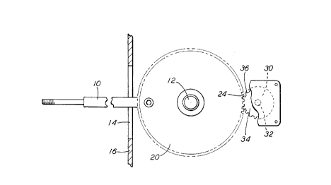
Figure 1 is a side view of a presently preferred embodiment
of this invention, with the axis of the control handle axle
perpendicular to the plane of the paper.
Figure 2 is another side view of the apparatus shown in
Figure 1, with the axis of the control handle lying in the plane
of the paper, further showing the control handle and first gear
in cross-section.
DESCRIPTION OF A PREFERRED EMBODIMENT OF THE INVENTION
Referring now to the two drawings, illustrated therein are
two side views of the inventive apparatus of a presently
preferred embodiment of this invention, wherein a control handle
10 is to be selectively positioned. The control handle 10 is
representative of either a throttle control handle or a dynamic
brake control handle, or even a reverser control handle. As in
any typical control stand, the control handle 10 is secured for
sglD 8
~,
rotational movement on an axle 12 within the control stand, and
extends through an elongated slot 14, in face plate 16, of the
control stand (not otherwise shown). A first circular gear 20,
is perpendicularly secured to axle 12 for rotation with handle
10 on axle 12. As shown in this particular embodiment, first
circular gear 20 is secured perpendicularly to axle 12, and
control handle 10 is secured to gear 20. A set screw 22 is
provided to interlock gear 20 and control handle 10, to assure
that gear 20 will rotate with the pivotal rotation of handle 10.
In this way, it makes no difference whether axle 12 actually
rotates with control handle 10. As may be further apparent, the
pivotal rotation of control handle 10 is limited by the ends of
slot 14, to a pivotal rotation of approximately 80 degrees.
A rotary optical encoder 30, is rigidly attached to a
structural element (not shown) such that the disk axle 32 on the
encoder 30 is parallel to axle 12 and aligned adjacent to gear
20. A second circular gear 34 is rigidly attached to disk axle
32 and adapted such that gear teeth 36 thereon mesh with the
gear teeth 24 on first circular gear 20. It should be apparent,
therefore, that any pivotal movement of control handle 10 will
cause a partial rotational movement of first circular gear 20,
and a corresponding
Sglu 9
21gO90~
rotation of second circular gear 34 and disk axle 32. The crux of
this invention resides in the drive transfer means, namely, first
and second circular gears 20 and 34, and the relationship between
them, which comprise the drive transfer means. Specifically, the
diameters of the two gears 20 and 34 should be such that a full
pivotal movement of control handle 10, as limited by slot 14, will
cause disk axle 32 to rotate through an angle of no more than 360
degrees, but more than the angle through which first circular
gear 20 is rotated. Accordingly, by rotating disk axle 32 through
an angle greater that the angle of rotation of control handle 10,
it should be apparent that a greater degree of sensitivity of the
rotary optical encoder 30 can be utilized, for purposes of deriving
a more exacting and absolute position indication of the handle 10.
It should be further apparent, however, that disk axle 32 should
not be rotatable through an angle of more than 360 degrees, for
purposes of avoiding any over-lapping of positions at the extreme
ends of the rotational movement, which would cause different
positions to be identically encoded.
In the preferred embodiment employed, the drive transfer
means; i.e., gears 20 and 34, are sized to provide a 4:1 rotational
ratio. Since the control stand will normally permit control
handle 10 to be pivoted through an angle of about 80 degrees, the
4:1 ratio will allow the disk axle 32, on encoder 30, to be rotated
through an angle of about 320 degrees, and accordingly the
sensitivity of the of the apparatus is quadrupled as compared to an
encoder 30 directly connected to axle 12 in a 1:1 rotational relati~hir.
While it is believed that practically any sort of a rotational
encoder could be made to work, an absolute optical encoder is
highly preferred. Specifically, the preferred encoder has been
an absolute encoder as produced by Computer Optical Products,
Inc., of 9305 Eton Avenue, Chatsworth, California, part number
CP-350-008AN-WAB, which is a specially version, 8-bit absolute
analog encoder.
In practice, the above described absolute optical encoder
has a resolution of 360; i.e., having a capability of producing
a signal each degree of rotation of the encoder disk, and
produces a current signal of from 4 to 20 milliampere. The
milliampere current signal is converted to a voltage signal for
transmission to the microcomputer.
As should be apparent from the above detailed description,
a number of modifications and other embodiments could be
incorporated without departing from the spirit of the invention.
For example, a variety of different types of rotational encoders
could be utilized as suggested above. While the drive transfer
means has been shown to be a pair of gears 20 and 32 aligned and
positioned in a single plane, it is obvious that means other
than gear could be utilized, such as a chain, for example, and
that other gear arrangement could be utilized, and that the
gears need not be disposed in a single plane. Obviously, gears
intermeshing at an angle would work equally well. Therefore,
while the detailed description above represents the preferred
technique and apparatus as utilized in the presently preferred
embodiment, and represents perhaps the most simple technique to
achieve the desired results,
Sg/~ 1 1
-- 2140401
it should be apparent that a great number of changes could be
incorporated without departing from the spirit of the invention.