Language selection

Search

Patent 2140769 Summary

Third-party information liability

Some of the information on this Web page has been provided by external sources. The Government of Canada is not responsible for the accuracy, reliability or currency of the information supplied by external sources. Users wishing to rely upon this information should consult directly with the source of the information. Content provided by external sources is not subject to official languages, privacy and accessibility requirements.

Claims and Abstract availability

Any discrepancies in the text and image of the Claims and Abstract are due to differing posting times. Text of the Claims and Abstract are posted:

  • At the time the application is open to public inspection;
  • At the time of issue of the patent (grant).
(12) Patent Application: (11) CA 2140769
(54) English Title: IMPROVEMENTS RELATING TO FLUID CONTAINERS
(54) French Title: AMELIORATIONS RELATIVES AUX RECIPIENTS A LIQUIDE
Status: Deemed Abandoned and Beyond the Period of Reinstatement - Pending Response to Notice of Disregarded Communication
Bibliographic Data
(51) International Patent Classification (IPC):
  • B05B 09/08 (2006.01)
  • B05B 09/04 (2006.01)
(72) Inventors :
  • MANSFIELD, ANDREW C. (United Kingdom)
(73) Owners :
  • PAN BRITANNICA INDUSTRIES LIMITED
(71) Applicants :
  • PAN BRITANNICA INDUSTRIES LIMITED (United Kingdom)
(74) Agent: SMART & BIGGAR LP
(74) Associate agent:
(45) Issued:
(86) PCT Filing Date: 1993-08-06
(87) Open to Public Inspection: 1994-02-17
Availability of licence: N/A
Dedicated to the Public: N/A
(25) Language of filing: English

Patent Cooperation Treaty (PCT): Yes
(86) PCT Filing Number: PCT/GB1993/001677
(87) International Publication Number: GB1993001677
(85) National Entry: 1995-01-20

(30) Application Priority Data:
Application No. Country/Territory Date
9216889.7 (United Kingdom) 1992-08-08

Abstracts

English Abstract


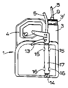
A container (1) comprises a body (2) in which fluid to be dispensed can be stored. The body has a fluid outlet (3') to which
one end of a flexible hose (5) is attached. An opposite discharge end (6) of the hose (5) has a spray lance (7) attached to it. Attach-
ment means (14, 15, 16, 17), such as a tube embedded in a recess is provided on a side wall of the body to retain the discharge end
(6) of the hose (5) releasably to the body when the container (1) is not in use. The container (1) may be used to discharge liquids
such as fertilisers, pesticides or other chemical agents in the form of a spray.


Claims

Note: Claims are shown in the official language in which they were submitted.

CLAIMS
1. A container (1) adapted to dispense fluid
comprising a body (2) in which fluid to be dispensed
can be stored, a fluid outlet (3') from the body (2),
and a flexible hose (5) connectable at one end to the
fluid outlet (3') and having an opposite discharge
end (6), and attachment means (14,15,16,17) on the
body (2) adapted to retain the discharge end (6) of the
hose (5) releasably in a recess (14) in a wall of the
body (2) when the container (1) is not in use.
2. A container (1) according to Claim 1 characterised
in that the attachment means (14,15,16,17) co-operates
directly with the discharge end (6) of the hose (5) to
retain the discharge end (6) to the body (2).
3. A container (1) according to Claim 1 characterised
in that the discharge end (6) has a lance (7) attached
thereto and the attachment means (14,15,16,17)
co-operates with the lance (7) to retain the discharge
end (6) to the body (2).
4. A container (1) according to any preceding claim
characterised in that the attachment
means (14,15,16,17) is provided at a side wall of the
body (2).
5. A container (1) according to any preceding claim
characterised in that the attachment
means (14,15,16,17) includes an item (17) formed
separately from the body (2) which is connected to the
body (2) at the recess (14) and retained thereto by
latch means (15,16) provided on the body (2).

6. A container (1) according to any preceding claim
characterised in that the attachment
means (14,15,16,17) comprises a holster or tube (17)
fixed to the exterior of the body (2) in the
recess (14) to receive the discharge end (6) of the
hose (5) or the lance (7).
7. A container (1) according to Claim 6 characterised
in that the holster or tube (17) is embedded in the
recess (14).
8. A container (1) according to claim 6 or claim 7
characterised in that the holster or tube (17) is
permanently fixed to the body (2).
9. A container (1) according to characterised in that
the lance (7) has a sliding fit in the holster or
tube (17).

Description

Note: Descriptions are shown in the official language in which they were submitted.


2:l4o769
IMPROVEMENTS RELATING TO FLUID CONTAINERS
This invention relates to fluid containers and in
particular to fluid containers having a flexible hose
through which fluid is discharged.
Known fluid, or more particularly liquid,
containers of this kind generally have an outlet at
their upper region from which a supply of fluid can be
taken. The outlet may also be used as a means of
refilling the container with fluid. A hose is
connected to the outlet for the discharge of fluid from
the container. A spray lance may be attached to a
discharge end of the hose and may comprise a nozzle
attached to a body. Pumping means to move the fluid
from the container to the spray lance through the hose
may be provided either i-n relation to the container or
the lance.
A disadvantage of this kind of container is that
when it is stored, left for a short time, or carried,
the hose, and if provided the lance, may hang or extend
freely from the container and may become damaged or
entangled. It is known from US 4192464 to provide a
slotted tube on a wall of the container to carry the
lance when not in use, but this still leaves the lance
protruding and exposed to damage.
According to the present invention we provide a
container adapted to dispense fluid comprising a body
in which fluid to be dispensed can be stored, a fluid
outlet from the body, and a flexible hose connectable
at one end to the fluid outlet and having an opposite
discharge end, and attachment means on the body adapted
to retain the discharge end of the hose releasably in a
recess in a wall of the body when the container is not
in use.
~EN~

- 21gl~76g
-
The attachment means may co-operate directly~ with
the discharge end of the hose to retain the discharge
end to the body. Preferably the discharge end has a
lance attached thereto and the attachment means
co-operates with the lance to retain the discharge end
to the body. The attachment means may be provided at
a side wall of the body. The attachment means may
comprise one or more clips or lugs adapted to retain
the hose or lance. The clip or clips may line the
recess. The attachment means may be integrally formed
with the body. Alternatively the attachment means may
include an item formed separately from the body which
is connected to the body and retained thereto by latch
means provided on the body. In one convenient form the
attachment means comprises a holster or tube fixed to
the exterior of the body to receive the discharge end
of the hose or the lance. The holster or tube may be
embedded in an external recess in a wall of the body.
The holster or tube may be permanently fixed to the
body.
Preferably the attachment means is a tube which
locates a spray lance connected to the hose. The lance
may have a member which is a sliding fit in the tube.
The tube may be provided with a slot running along its
length thus enabling the lance to be clipped directly
into the tube.
Preferably the container is adapted to dispense
liquid as a spray. The liquid may, for example, be a
fertilizer, pesticide or other chemical agent used in
agriculture, horticulture, or domestic, industrial or
amenity usage.
A container embodying the invention will now be
described by way of example only with reference to the
accompanying drawings of which:
A~EN~E~ SHEET

, '21~0769
W094/03278 PCT/GB93/01677
-
Figure 1 is a rear view of the container;
Figure 2 is a side view of the container showing
a lance retained within attachment means of the
container; and
Figure 3 is a plan view of the container.
The container 1 shown in the accompanying drawings
is in the form of a sprày dispenser and has a generally
rectangular body part 2 in which liquid to be dispensed
is stored and from which integrally extends upwardly a
neck 3 and a handle 4. At the top of the neck 3 there
is an outlet 3'. A flexible hose 5 is attached at one
end to the outlet 3' by a connector ~ which is
screw-threadedly connected to the outlet. An opposite,
discharge end 6 of the hose 5 has a spray lance 7
attached to it.
The body part 2, neck 3 and handle 4 of the
container are combined in a unitary moulding made from
a suitably durable plastics material which additionally
is resistant to a wide range of chemicals, including
for example nitrate based fertilizers or solvents.
Polyethylene is a suitable material whether by itself
or co-extruded with other polymers.
The spray lance 7 consists of a body portion 10
comprising a central part 11 and a handle 12. A
trigger 13 is pivoted to the central part 11 and
repetitive movements of the trigger towards the handle
cause a pump (not shown) in the central part to draw
liquid from the body part 2 through the hose 5 and to
drive the liquid through a delivery nozzle 8 which
extends from the body portion 10.

~ ' ~
W094/03278 PCT/GB93/01677
214076g
A recess 14 is moulded into a side wall of the
body part 2 of the container. The recess 14, which
extends vertically when the container is upright as
shown in the drawings, is U-shaped in cross-section and
is sunken into the side wall of the body part 2. Four
clips lS, 16 integrally formed with the side wall are
arranged in pairs along the recess 14, two clips 15 at
its upper end and two clips 16 at its lower end. The
clips 15, 16 of each pair are directed towards one
another and partially overlie the recess.
A metal or plastics tube 17 is located in the
recess 14 and is of a size and shape such that its
outer surface corresponds with and fits against the
inner semi-circular surface of the recess. The
clips 15 and 16 overlap and bear on the tube 17 such
that the tube is fixed against movement in the recess.
The container 1 is a hand held portable dispenser
such as may be used for spraying liquids used in
agriculture and/or horticulture or domestic, industrial
or amenity usage. A user carries the container in one
hand by its handle 4. The body part 2 may be, say, of
three-litre capacity and contain fertilizer or
pesticide in a diluted form. The user holds the spray
lance 7 in his other hand. By squeezing on the
trigger 13 the liquid is delivered through the nozzle 8
in a spray.
The hose may possibly be disconnected from the
outlet 3' and a screw cap, not shown, fitted instead to
close off the outlet. A similar dispenser filled with
liquid and closed by a screw cap, without the hose and
spray lance, may be supplied as a replacement for an
emptied container and be fitted with the hose and spray
lance of the latter.

2i 9076g
W094/03278 PCT/GB93/01677
The nozzle 8 of the spray lance 7 can fit into the
tube 17 as a sliding fit as shown in ~igure 2. In this
way the lance 7 can be stowed away in the tube and
retained while the container is not in use, for example
if it is stored or while the container is being
carried. Therefore the lance 7 and hose 5 are kept out
of harms way and less likely to be damaged or become
entangled with one another and/or with other articles
or people.
.A

Representative Drawing
A single figure which represents the drawing illustrating the invention.
Administrative Status

2024-08-01:As part of the Next Generation Patents (NGP) transition, the Canadian Patents Database (CPD) now contains a more detailed Event History, which replicates the Event Log of our new back-office solution.

Please note that "Inactive:" events refers to events no longer in use in our new back-office solution.

For a clearer understanding of the status of the application/patent presented on this page, the site Disclaimer , as well as the definitions for Patent , Event History , Maintenance Fee  and Payment History  should be consulted.

Event History

Description Date
Inactive: IPC from MCD 2006-03-11
Time Limit for Reversal Expired 1999-08-06
Application Not Reinstated by Deadline 1999-08-06
Deemed Abandoned - Failure to Respond to Maintenance Fee Notice 1998-08-06
Application Published (Open to Public Inspection) 1994-02-17

Abandonment History

Abandonment Date Reason Reinstatement Date
1998-08-06

Maintenance Fee

The last payment was received on 1997-06-24

Note : If the full payment has not been received on or before the date indicated, a further fee may be required which may be one of the following

  • the reinstatement fee;
  • the late payment fee; or
  • additional fee to reverse deemed expiry.

Patent fees are adjusted on the 1st of January every year. The amounts above are the current amounts if received by December 31 of the current year.
Please refer to the CIPO Patent Fees web page to see all current fee amounts.

Fee History

Fee Type Anniversary Year Due Date Paid Date
MF (application, 4th anniv.) - standard 04 1997-08-06 1997-06-24
Owners on Record

Note: Records showing the ownership history in alphabetical order.

Current Owners on Record
PAN BRITANNICA INDUSTRIES LIMITED
Past Owners on Record
ANDREW C. MANSFIELD
Past Owners that do not appear in the "Owners on Record" listing will appear in other documentation within the application.
Documents

To view selected files, please enter reCAPTCHA code :


To view images, click a link in the Document Description column. To download the documents, select one or more checkboxes in the first column and then click the "Download Selected in PDF format (Zip Archive)" or the "Download Selected as Single PDF" button.

List of published and non-published patent-specific documents on the CPD .

If you have any difficulty accessing content, you can call the Client Service Centre at 1-866-997-1936 or send them an e-mail at CIPO Client Service Centre.


Document
Description 
Date
(yyyy-mm-dd) 
Number of pages   Size of Image (KB) 
Abstract 1994-02-16 1 44
Description 1994-02-16 5 175
Claims 1994-02-16 2 51
Drawings 1994-02-16 1 18
Representative drawing 1997-06-17 1 6
Courtesy - Abandonment Letter (Maintenance Fee) 1998-09-02 1 189
Fees 1996-07-15 1 38
Fees 1995-06-20 1 51
International preliminary examination report 1995-01-19 13 338
Courtesy - Office Letter 1995-03-08 1 20