Sélection de la langue

Search

Sommaire du brevet 2140769 

Énoncé de désistement de responsabilité concernant l'information provenant de tiers

Une partie des informations de ce site Web a été fournie par des sources externes. Le gouvernement du Canada n'assume aucune responsabilité concernant la précision, l'actualité ou la fiabilité des informations fournies par les sources externes. Les utilisateurs qui désirent employer cette information devraient consulter directement la source des informations. Le contenu fourni par les sources externes n'est pas assujetti aux exigences sur les langues officielles, la protection des renseignements personnels et l'accessibilité.

Disponibilité de l'Abrégé et des Revendications

L'apparition de différences dans le texte et l'image des Revendications et de l'Abrégé dépend du moment auquel le document est publié. Les textes des Revendications et de l'Abrégé sont affichés :

  • lorsque la demande peut être examinée par le public;
  • lorsque le brevet est émis (délivrance).
(12) Demande de brevet: (11) CA 2140769
(54) Titre français: AMELIORATIONS RELATIVES AUX RECIPIENTS A LIQUIDE
(54) Titre anglais: IMPROVEMENTS RELATING TO FLUID CONTAINERS
Statut: Réputée abandonnée et au-delà du délai pour le rétablissement - en attente de la réponse à l’avis de communication rejetée
Données bibliographiques
(51) Classification internationale des brevets (CIB):
  • B05B 09/08 (2006.01)
  • B05B 09/04 (2006.01)
(72) Inventeurs :
  • MANSFIELD, ANDREW C. (Royaume-Uni)
(73) Titulaires :
  • PAN BRITANNICA INDUSTRIES LIMITED
(71) Demandeurs :
  • PAN BRITANNICA INDUSTRIES LIMITED (Royaume-Uni)
(74) Agent: SMART & BIGGAR LP
(74) Co-agent:
(45) Délivré:
(86) Date de dépôt PCT: 1993-08-06
(87) Mise à la disponibilité du public: 1994-02-17
Licence disponible: S.O.
Cédé au domaine public: S.O.
(25) Langue des documents déposés: Anglais

Traité de coopération en matière de brevets (PCT): Oui
(86) Numéro de la demande PCT: PCT/GB1993/001677
(87) Numéro de publication internationale PCT: GB1993001677
(85) Entrée nationale: 1995-01-20

(30) Données de priorité de la demande:
Numéro de la demande Pays / territoire Date
9216889.7 (Royaume-Uni) 1992-08-08

Abrégés

Abrégé anglais


A container (1) comprises a body (2) in which fluid to be dispensed can be stored. The body has a fluid outlet (3') to which
one end of a flexible hose (5) is attached. An opposite discharge end (6) of the hose (5) has a spray lance (7) attached to it. Attach-
ment means (14, 15, 16, 17), such as a tube embedded in a recess is provided on a side wall of the body to retain the discharge end
(6) of the hose (5) releasably to the body when the container (1) is not in use. The container (1) may be used to discharge liquids
such as fertilisers, pesticides or other chemical agents in the form of a spray.

Revendications

Note : Les revendications sont présentées dans la langue officielle dans laquelle elles ont été soumises.


CLAIMS
1. A container (1) adapted to dispense fluid
comprising a body (2) in which fluid to be dispensed
can be stored, a fluid outlet (3') from the body (2),
and a flexible hose (5) connectable at one end to the
fluid outlet (3') and having an opposite discharge
end (6), and attachment means (14,15,16,17) on the
body (2) adapted to retain the discharge end (6) of the
hose (5) releasably in a recess (14) in a wall of the
body (2) when the container (1) is not in use.
2. A container (1) according to Claim 1 characterised
in that the attachment means (14,15,16,17) co-operates
directly with the discharge end (6) of the hose (5) to
retain the discharge end (6) to the body (2).
3. A container (1) according to Claim 1 characterised
in that the discharge end (6) has a lance (7) attached
thereto and the attachment means (14,15,16,17)
co-operates with the lance (7) to retain the discharge
end (6) to the body (2).
4. A container (1) according to any preceding claim
characterised in that the attachment
means (14,15,16,17) is provided at a side wall of the
body (2).
5. A container (1) according to any preceding claim
characterised in that the attachment
means (14,15,16,17) includes an item (17) formed
separately from the body (2) which is connected to the
body (2) at the recess (14) and retained thereto by
latch means (15,16) provided on the body (2).

6. A container (1) according to any preceding claim
characterised in that the attachment
means (14,15,16,17) comprises a holster or tube (17)
fixed to the exterior of the body (2) in the
recess (14) to receive the discharge end (6) of the
hose (5) or the lance (7).
7. A container (1) according to Claim 6 characterised
in that the holster or tube (17) is embedded in the
recess (14).
8. A container (1) according to claim 6 or claim 7
characterised in that the holster or tube (17) is
permanently fixed to the body (2).
9. A container (1) according to characterised in that
the lance (7) has a sliding fit in the holster or
tube (17).

Description

Note : Les descriptions sont présentées dans la langue officielle dans laquelle elles ont été soumises.

2:l4o769
IMPROVEMENTS RELATING TO FLUID CONTAINERS
This invention relates to fluid containers and in
particular to fluid containers having a flexible hose
through which fluid is discharged.
Known fluid, or more particularly liquid,
containers of this kind generally have an outlet at
their upper region from which a supply of fluid can be
taken. The outlet may also be used as a means of
refilling the container with fluid. A hose is
connected to the outlet for the discharge of fluid from
the container. A spray lance may be attached to a
discharge end of the hose and may comprise a nozzle
attached to a body. Pumping means to move the fluid
from the container to the spray lance through the hose
may be provided either i-n relation to the container or
the lance.
A disadvantage of this kind of container is that
when it is stored, left for a short time, or carried,
the hose, and if provided the lance, may hang or extend
freely from the container and may become damaged or
entangled. It is known from US 4192464 to provide a
slotted tube on a wall of the container to carry the
lance when not in use, but this still leaves the lance
protruding and exposed to damage.
According to the present invention we provide a
container adapted to dispense fluid comprising a body
in which fluid to be dispensed can be stored, a fluid
outlet from the body, and a flexible hose connectable
at one end to the fluid outlet and having an opposite
discharge end, and attachment means on the body adapted
to retain the discharge end of the hose releasably in a
recess in a wall of the body when the container is not
in use.
~EN~

- 21gl~76g
-
The attachment means may co-operate directly~ with
the discharge end of the hose to retain the discharge
end to the body. Preferably the discharge end has a
lance attached thereto and the attachment means
co-operates with the lance to retain the discharge end
to the body. The attachment means may be provided at
a side wall of the body. The attachment means may
comprise one or more clips or lugs adapted to retain
the hose or lance. The clip or clips may line the
recess. The attachment means may be integrally formed
with the body. Alternatively the attachment means may
include an item formed separately from the body which
is connected to the body and retained thereto by latch
means provided on the body. In one convenient form the
attachment means comprises a holster or tube fixed to
the exterior of the body to receive the discharge end
of the hose or the lance. The holster or tube may be
embedded in an external recess in a wall of the body.
The holster or tube may be permanently fixed to the
body.
Preferably the attachment means is a tube which
locates a spray lance connected to the hose. The lance
may have a member which is a sliding fit in the tube.
The tube may be provided with a slot running along its
length thus enabling the lance to be clipped directly
into the tube.
Preferably the container is adapted to dispense
liquid as a spray. The liquid may, for example, be a
fertilizer, pesticide or other chemical agent used in
agriculture, horticulture, or domestic, industrial or
amenity usage.
A container embodying the invention will now be
described by way of example only with reference to the
accompanying drawings of which:
A~EN~E~ SHEET

, '21~0769
W094/03278 PCT/GB93/01677
-
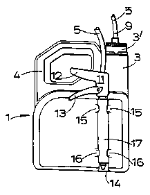
Figure 1 is a rear view of the container;
Figure 2 is a side view of the container showing
a lance retained within attachment means of the
container; and
Figure 3 is a plan view of the container.
The container 1 shown in the accompanying drawings
is in the form of a sprày dispenser and has a generally
rectangular body part 2 in which liquid to be dispensed
is stored and from which integrally extends upwardly a
neck 3 and a handle 4. At the top of the neck 3 there
is an outlet 3'. A flexible hose 5 is attached at one
end to the outlet 3' by a connector ~ which is
screw-threadedly connected to the outlet. An opposite,
discharge end 6 of the hose 5 has a spray lance 7
attached to it.
The body part 2, neck 3 and handle 4 of the
container are combined in a unitary moulding made from
a suitably durable plastics material which additionally
is resistant to a wide range of chemicals, including
for example nitrate based fertilizers or solvents.
Polyethylene is a suitable material whether by itself
or co-extruded with other polymers.
The spray lance 7 consists of a body portion 10
comprising a central part 11 and a handle 12. A
trigger 13 is pivoted to the central part 11 and
repetitive movements of the trigger towards the handle
cause a pump (not shown) in the central part to draw
liquid from the body part 2 through the hose 5 and to
drive the liquid through a delivery nozzle 8 which
extends from the body portion 10.

~ ' ~
W094/03278 PCT/GB93/01677
214076g
A recess 14 is moulded into a side wall of the
body part 2 of the container. The recess 14, which
extends vertically when the container is upright as
shown in the drawings, is U-shaped in cross-section and
is sunken into the side wall of the body part 2. Four
clips lS, 16 integrally formed with the side wall are
arranged in pairs along the recess 14, two clips 15 at
its upper end and two clips 16 at its lower end. The
clips 15, 16 of each pair are directed towards one
another and partially overlie the recess.
A metal or plastics tube 17 is located in the
recess 14 and is of a size and shape such that its
outer surface corresponds with and fits against the
inner semi-circular surface of the recess. The
clips 15 and 16 overlap and bear on the tube 17 such
that the tube is fixed against movement in the recess.
The container 1 is a hand held portable dispenser
such as may be used for spraying liquids used in
agriculture and/or horticulture or domestic, industrial
or amenity usage. A user carries the container in one
hand by its handle 4. The body part 2 may be, say, of
three-litre capacity and contain fertilizer or
pesticide in a diluted form. The user holds the spray
lance 7 in his other hand. By squeezing on the
trigger 13 the liquid is delivered through the nozzle 8
in a spray.
The hose may possibly be disconnected from the
outlet 3' and a screw cap, not shown, fitted instead to
close off the outlet. A similar dispenser filled with
liquid and closed by a screw cap, without the hose and
spray lance, may be supplied as a replacement for an
emptied container and be fitted with the hose and spray
lance of the latter.

2i 9076g
W094/03278 PCT/GB93/01677
The nozzle 8 of the spray lance 7 can fit into the
tube 17 as a sliding fit as shown in ~igure 2. In this
way the lance 7 can be stowed away in the tube and
retained while the container is not in use, for example
if it is stored or while the container is being
carried. Therefore the lance 7 and hose 5 are kept out
of harms way and less likely to be damaged or become
entangled with one another and/or with other articles
or people.
.A

Dessin représentatif
Une figure unique qui représente un dessin illustrant l'invention.
États administratifs

2024-08-01 : Dans le cadre de la transition vers les Brevets de nouvelle génération (BNG), la base de données sur les brevets canadiens (BDBC) contient désormais un Historique d'événement plus détaillé, qui reproduit le Journal des événements de notre nouvelle solution interne.

Veuillez noter que les événements débutant par « Inactive : » se réfèrent à des événements qui ne sont plus utilisés dans notre nouvelle solution interne.

Pour une meilleure compréhension de l'état de la demande ou brevet qui figure sur cette page, la rubrique Mise en garde , et les descriptions de Brevet , Historique d'événement , Taxes périodiques et Historique des paiements devraient être consultées.

Historique d'événement

Description Date
Inactive : CIB de MCD 2006-03-11
Le délai pour l'annulation est expiré 1999-08-06
Demande non rétablie avant l'échéance 1999-08-06
Réputée abandonnée - omission de répondre à un avis sur les taxes pour le maintien en état 1998-08-06
Demande publiée (accessible au public) 1994-02-17

Historique d'abandonnement

Date d'abandonnement Raison Date de rétablissement
1998-08-06

Taxes périodiques

Le dernier paiement a été reçu le 1997-06-24

Avis : Si le paiement en totalité n'a pas été reçu au plus tard à la date indiquée, une taxe supplémentaire peut être imposée, soit une des taxes suivantes :

  • taxe de rétablissement ;
  • taxe pour paiement en souffrance ; ou
  • taxe additionnelle pour le renversement d'une péremption réputée.

Les taxes sur les brevets sont ajustées au 1er janvier de chaque année. Les montants ci-dessus sont les montants actuels s'ils sont reçus au plus tard le 31 décembre de l'année en cours.
Veuillez vous référer à la page web des taxes sur les brevets de l'OPIC pour voir tous les montants actuels des taxes.

Historique des taxes

Type de taxes Anniversaire Échéance Date payée
TM (demande, 4e anniv.) - générale 04 1997-08-06 1997-06-24
Titulaires au dossier

Les titulaires actuels et antérieures au dossier sont affichés en ordre alphabétique.

Titulaires actuels au dossier
PAN BRITANNICA INDUSTRIES LIMITED
Titulaires antérieures au dossier
ANDREW C. MANSFIELD
Les propriétaires antérieurs qui ne figurent pas dans la liste des « Propriétaires au dossier » apparaîtront dans d'autres documents au dossier.
Documents

Pour visionner les fichiers sélectionnés, entrer le code reCAPTCHA :


Pour visualiser une image, cliquer sur un lien dans la colonne description du document. Pour télécharger l'image (les images), cliquer l'une ou plusieurs cases à cocher dans la première colonne et ensuite cliquer sur le bouton "Télécharger sélection en format PDF (archive Zip)" ou le bouton "Télécharger sélection (en un fichier PDF fusionné)".

Liste des documents de brevet publiés et non publiés sur la BDBC .

Si vous avez des difficultés à accéder au contenu, veuillez communiquer avec le Centre de services à la clientèle au 1-866-997-1936, ou envoyer un courriel au Centre de service à la clientèle de l'OPIC.


Description du
Document 
Date
(aaaa-mm-jj) 
Nombre de pages   Taille de l'image (Ko) 
Abrégé 1994-02-16 1 44
Description 1994-02-16 5 175
Revendications 1994-02-16 2 51
Dessins 1994-02-16 1 18
Dessin représentatif 1997-06-17 1 6
Courtoisie - Lettre d'abandon (taxe de maintien en état) 1998-09-02 1 189
Taxes 1996-07-15 1 38
Taxes 1995-06-20 1 51
Rapport d'examen préliminaire international 1995-01-19 13 338
Courtoisie - Lettre du bureau 1995-03-08 1 20