Note: Descriptions are shown in the official language in which they were submitted.
"' WO 94/02188 ~ ~ PCT/US93/06940
1
DESCRIPTION
NEEDLELEBB HYPODERMIC INJECTION METHODB l~TD DEVICE
FIELD OF THE INVENTION
The field of the present invention is needleless
hypodenaic injection methods and devices.
Various needleless hypodermic injection devices have
been known and used in the past. These devices, also
known as jet injectors, typically use spring or compressed
gas driven plungers to accelerate an injectant to a
velocity sufficient to pierce through the skin and enter
the underlying tissues.
While large j et inj ection apparatus have been success-
fully used for mass inoculations, e.g. in the military
services, these apparatus are relatively complex, costly,
limited in performance and are not portable. Thus,
injections using needles remain as the standard despite
their disadvantages (for example, accidental needle sticks
and risk of spreading infection to both the patient and
medical professional; safe disposal of the used needle,
patient's fear of needles: and pain caused by needle
. injections). Jet injection avoids or diminishes these
disadvantages.
Although many portable needleless injectors have been
proposed, these known devices have not achieved widespread
acceptance in the medical field, due to a variety of
f actors .
WO 94/02188 PCT/US93/0694cr
2
Significantly, the characteristics of needleless or
jet injections typically vary'with the pressures exerted
by the injection device, the nozzle diameter of the
ampule, the patient's size, age and weight, the nature of
the injection site, and the viscosity of the injectant.
A long standing basic difficulty with jet injection
has been the complex problem of deter'~ining which are the
preferred injection variables. These variables include:
1) pressure profile, 2) nozzle size, 3) patient factors,
i.e., age, sex and size, 4) injection site, and 5) medica-
tion viscosity. The repeated failures of the prior art to
adequately solve these complex variables problems has
contributed to the lack of acceptance of a handheld and
portable jet injector in the medical community.
The pressure profile is the pressure exerted on the
liquid injectant, typically measured over time, from the
beginning to the end of the injection. The pressure
profile must be selected, in combination with the nozzle
size and other factors, to deliver the injectant through
the skin to the desired depth, preferably with minimum
pain.
The patient factors are also important. Gender is
significant as women typically have a different adipose
distribution than men. Men also typically have tougher
tissue that women. The patient's age is important because
infants are born with very little muscle, thick layers of
adipose, and very easily penetrated skin. As infants age
and become mobile the adipose is gradually replaced by
WO 94/02188
2 ~ 4 ~ 7 7 ~ PCT/US93/06940
3
muscle. At adolescence the introduction of hormones
- changes tissue composition. Aging through mid-life is
usually associated with gradual weight gain and decrease
in tissue strength.
Injection sites are very significant because in all
patients the thickness of the skin and adipose tissue
varies at different regions of the body. The medical
profession has established generally accepted injection
sites for conventional needle syringes that are best
suited for specific types of injection. The subcutaneous
sites typically have a thick adipose layer and are free of
major nerves and vasculature. Intramuscular sites typi-
cally have a thin adipose layer, a thick muscle layer, and
are free of major nerves and vasculature.
Finally, the viscosity of the injectant must be
considered as it effects characteristics of the jet
injection. In addition, it has been discovered that
viscosity effects have been widely misunderstood in the
prior art.
The prior art has generally not been able to overcome
the complexities and difficulties of simultaneously
accounting for all of the foregoing variables. Thus, jet
injection, despite its great potential advantages, remains
virtually unused. Accordingly, it is an object of the
'25 invention to provide improved methods and devices for
needleless injection, so that the advantages of jet
injection may be brought into use.
CA 02140772 2005-05-04
6379E~-494
4
DISCLOSURE OF THE INVENTION
To these ends, in a needleless injection device,
actuation of the device initially causes a valve to open.
The device engages a plunger extending from an ampule. The
plunder is then driven into the ampule generating a high
velocity jet of injectant from the nozzle of the ampule.
variable doses of injectant can be provided as the device
can engage any position of the plunger regardless of the
plunger position.
l0 An interlock system is advantageously provided to
prevent the trigger from actuating the initiator valve
unle:~s~an ampule is properly installed in the device.
Preferably, filters prevent stray liquefied compressed gas
from entering into internal chambers of the device.
In novel methods of needleless injection, the
pres;~ure profiles of the injectant, nozzle diameter, patient
and injection site parameters, as well as injectant
viscosity, are selected to achieve desired injection
characteristics.
According to one aspect of the present invention,
there. is provided a method of providing a jet injection by
pressurizing a fluid injectant within an ampule, comprising
the steps of: driving a plunger into the ampule with
sufficient force to generate a pressure of from
26000-30000 kPa within 6 milliseconds; reducing the pressure
generally linearly until 0.5 ml is expelled and the pressure
CA 02140772 2005-05-04
63796-494
4a
is 8000-14000 kPa; maintaining the pressure at
8000-14000 kPa until a desired volume injectant is expelled
from the ampule; and reducing the pressure to about 0.0 kPa
within 5.0 milliseconds.
According to another aspect of the present
invention, there is provided a method as aforesaid wherein a
subcutaneous injection is performed at a standard
subcutaneous injection site using a nozzle diameter of from
0.07 to 0.13 mm.
WO 94/OZ188 2 O ~ ~ PCT/US93/06940
BRIEF DEBCRIPTION OF THE DRAWIN~iB
In the drawings, wherein similar reference characters
denote similar elements throughout the several views:
Fig. 1 is a perspective view of the present needleless
5 injection device;
Fig. 2 is a section view of the present needleless
injection device taken along line 2-2 of Fig. 8:
Fig. 2a is a section view thereof further illustrating
an ampule and plunger installed in the device with the
device in a ready to inject position, except for the
piercing mechanism, Which is not shown having pierced the
cartridge:
Fig. 2b is a section view thereof illustrating a
clamping mechanism of the device in a pre-injection
position:
Fig. 2c is a section view thereof illustrating a drive
piston, clamping mechanism and plunger in a post-injection
position;
Fig. 3 is an enlarged view fragment of the section
view of Fig. 2, generally showing the back half of the
device:
Fig. 4 is an enlarged view fragment of the section
. view of Fig. 2, generally showing the front half of the
device;
'25 Figs. 4a and 4b are section view fragments thereof
showing an alternate embodiment;
Fig. 5 is a further enlarged section view fragment of
a valve shown in Fig. 3;
WO 94/02188 PCT/US93/06940
6
Fig. 6 is a partial section view fragment taken along
line 6-6 of Fig. 8 and showing selected features only;
Fig. 6a is a partial section view of a preferred
alternative housing and piston plenum shut-off valve
design;
Fig. 6b is a partial section view fragment of an
alternative preferred exhaust valve used in the housing
shown in Fig. 6a;
Fig. 6c is an enlarged partial section view of a bleed
gas valve shown in Fig. 6a;
Fig. 7 is an enlarged section view fragment of the
initiator valve:
Fig. 7a is a section view fragment of an alternate
preferred initiator valve body;
Fig. 7b is an enlarged section view fragment of an
alternative preferred initiator valve:
Fig. 8 is a back end elevation view of the device;
Fig. 9 is a front elevation view thereof;
Fig. 10 is a side elevation view in part section of
the present plunger and an ampule;
Fig. 10a, lOb and lOc are section view fragments of
alternate plunger and ampule embodiments;
Fig. 11 is a section view taken along line 11-11 of
Fig. 10;
Fig. 12 is a graphic illustration of operation of '
certain features of the present device;
Fig. 13 is a front elevation view of the indicator
ring shown in Fig. 4;
WO 94/02188 PCT/US93/06940
~t~o772
7
Fig. 13a is a side elevation view fragment taken along
line 13a-13a of Fig. 13;
Fig. 14 is a side elevation view thereof in part
section;
Fig. 15 is a graphic illustration of a pressure-volume
preferred injectant°pressure profile;
Fig. 16 is a schematic illustration of the present
peri-fascial needleless injection:
Fig. 17 is a table showing ampule selection and
to parameters; and
Figs. 18, 19, and 20 are graphic illustrations of
pressure-time preferred injectant pressure profiies for
ampules having 0.10, 0.20 and 0.36 mm diameter nozzles,
respectively.
MODEB FOR CARRYING OUT THE INVENTION
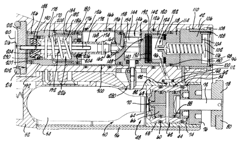
Turning now in detail to the drawings, as shown in
Figs. 1 and 2, an injector or needleless injection device
has a front end 22, a back end 24, a top surface 26 and
a bottom surface 28. A trigger 30 is slidably mounted on
20 the injector 20 adjacent the bottom surface 28. The
injector 20 includes an upper housing ~2 and a shorter
lower housing 44 attached to the upper housing 42. The
lower housing ~4 has a flat upper surface 82 which lies
against a flat lower surface 84 of the upper housing 42.
The upper housing ~2 and lower housing 44 are attached
together with four (4) pins 86.
WO 94/02188 ~ PCT/US93/0694U
8
The upper housing 42 and lower housing ~~ together are
sized and shaped to readily fit the user's hand, with the
user's palm resting over the top surface 26 and side of
the injector 20, and with the user's index finger easily
positionable over the trigger 30. The top surface 26 has
a step or incline 34 at approximately the center of the
injector 20. The upper and lower housings may alterna-
tively be formed as a single housing.
Turning to Fig. 3, the lower housing 44 is substan
tially hollow and defines a lower housing space 48.
Similarly, the upper housing 42 defines an upper housing
space ~6 (Fig. 6). Within the lower housing 44 is a
cartridge chamber 50 for receiving and holding a com
pressed gas cartridge 54, e.g., a C02 cartridge. A
cartridge seat 52 at the forward end of the cartridge
chamber 50 supports the back of the cartridge 54. A
generally u-shaped plastic cartridge chamber cover 56
snaps into place on the lower housing 44 over the car-
tridge chamber 50.
A generally cylindrical piercing housing 58 is slida-
bly positioned behind the cartridge chamber 50 within the
lower housing 44. O-rings 60 seal the piercing housing 58
against the lower housing 44 while allowing the piercing
housing 58 to slide within the lower housing 44. An
annulus 62 extends around the circumference of the pierc-
ing housing 58 in between the o-rings 60. A cylindrical
piercing body 66 is positioned within the piercing housing
58 and sealed against the piercing housing 58 by o-rings
WO 94/02188 ~ ~ ~ ~ 7 ~ PCT/US93/06940
9
88. A piercing point 68 extends forward from the front
surface of the piercing body 66 and is centrally aligned
with the neck of the cartridge 51. A seal 64 on the front
end of the piercing body 66 surrounds the piercing point
68. The seal 64 extends sufficiently forward to seal
against the neck of the--cartridge 54 before the piercing
point 68 penetrates into the cartridge 54.
A bore 70 extends through the piercing point 68 and
piercing body 66 connecting to the annulus 62. A piercing
body nut 74 threads into the back end of the piercing
housing 58, to secure the piercing body 66 and seal 64 in
position within and against the forward end of the pierc-
ing housing 58. A piercing housing nut 76 threads into
the back of the lower housing 44. Spanner tool openings
are provided in the piercing body nut 74 and the piercing
housing nut 76 for assembly purposes.
A threaded shaft 72 extends through and engages
threads in the piercing housing nut 76. A knob 78 at-
tached to the threaded shaft 72 has a flip handle 80 which
can be flipped up perpendicular to the plane of the knob
78 to allow the knob 78 and threaded shaft 72 to be more
easily turned by hand. The forward end of the threaded
shaft 72 bears against the back surface of the piercing
body 66.
A hole 92 extends through the upper surface 82 of the
lower housing to connect the annulus 62 to a bore 96
leading into the upper housing space 46. An o-ring 94
seals the connection of the hole 92 and bore 96.
WO 94/02188 PCT/US93/0694U
14o~~t~
At the back end of the upper housing 42 is a transpar-
ent window lens 98 secured to an end nut 108 by a rubber
window retainer i00. A Bourdon tube 116 is soldered into
a gauge base 114 and has an open end 124 extending into a
gauge chamber 122. The pointer 102,.extends perpendicular-
ly from the back end of the Bourdon,tube ii6. As shown in
Fig. 8, a gauge label 104 apg~ ied to the back end of a
gauge body 106 around the Bourdon tube 116 provides a
calibrated pressure scale with the scale and pointer
visible through the lens 98. Stop pins extending from the
back end of the gauge body 106 provide high and low
pressure end point stops for the pointer 102.
The end nut 108 has threads 110 at its forward end
which engage the upper housing 42. To calibrate the gauge
for a given pressure, the gauge body 106 is rotated
relative to the gauge base 114. When the correct index is
achieved, the gauge body 106 and gauge base 114 are
adhered together. A guiding pin 112 extends from the
upper housing 42 into a keyway groove and holds the gauge
body 106 in place while the end nut 108 is tightened.
Shims 118 are provided at the front surface at the
gauge base 114, as required, for proper stack up and
positioning of components in the upper housing 42.
An initiator valve housing 142 is spaced apart from
the gauge base 114 by a filter retainer ring 120. A
sandwiched assembly of filter disks 130 and synthetic
filters 132 are contained within the back end of the
housing 142. O-rings 140 seal the filter disks 130
WO 94/02188 21 ~ ~ ~ ~ PCT/US93/06940
11
against the retainer i40 and synthetic filter 132. O-ring
126 seals the filter retainer 140 within the upper housing
42. O-ring 126 and o-ring 150 seal the gauge chamber 122
such that compressed gas provided through the bore 96 can
flow out of the gauge chamber 122 only through the fil-
ters.
A port 148 extends t3irough the back wall of the
initiator valve housing 142 into an initiator valve
chamber 146 within the housing 142. An initiator valve
144 within the initiator valve chamber 146 controls gas
flow from the port 148 through the initiator valve chamber
146 to a reservoir port 154 formed through the forward
wall of the initiator valve housing 142.
A regulation valve 156 includes a regulation seat 158
formed around the reservoir port 154. A dart 160 moves
into and out of the regulation seat 158. The dart 160 has
a threaded dart shaft 162 threaded into the narrower tube
section at the back end of a poppet body 172. A dart pin
164 extending through the tube section of the poppet body
172 and the threaded dart shaft 162 secures the adjustment
of the longitudinal position of the dart 160 in relation
to the regulation seat 158. A reservoir spacer 166 within
. the upper housing 42 extends from the forward end of the
initiator valve housing 142 to a poppet housing 178,
forming a reservoir 168 around the tube section of the
poppet body 172. O-rings 126 seal the reservoir spacer
166 against the upper housing 42 and seal the initiator
valve housing 142 to the reservoir spacer 166.
WO 94/02188 PCT/US93/0694U
12
A poppet valve 170 within the poppet housing 178 has
a conical plastic poppet seat 188 centered within and
positioned against a forward wall of the poppet housing
178. Referring to Fig. 5, the poppet body 172 has a sharp
sealing edge 200 biased against thew.poppet seat 188 by a
compression spring 186 held in position within the poppet
housing 178 by a poppet nut 180. Alternatively, the
sealing edge 200 and poppet seat 188 may be configured
with unlike angles selected so that the inner diameter
contacts first, to minimize creep effects. The poppet nut
180 has a threaded forward section 184 engaged to a
threaded rear section i82 of the poppet housing 178. The
poppet nut 180 is turned to adjust the compression on the
spring 186 and correspondingly set the cracking pressure
of the poppet valve 170.
The diameter of the poppet seat 188 exposed to reser-
voir pressure prior to crack (thus that which governs
cracking pressure) remains constant although the conical
seat may creep, as the sealing surface, facing reservoir
pressure, is parallel to the axis of poppet movement.
The conical seat is attached to the poppet housing 178
rather than the poppet body 172 while all hard (poppet)
parts are made concentric and perpendicular. Thus,
irregularities in the seat 188 or soft part will creep to
conform to hard parts. The hard parts are free to rotate
but will still conform to the existing soft part deforma-
tion.
,...
WO 94/02188 - ~ ~ ~ ~ PCT/US93/06940
13
Sliding friction of the poppet body 172 is advanta-
geously minimized and consistent. Hence, the seal 206
used with the back up ring 204 may be a low friction seal.
In addition, since this seal is pressurized only after
cracking due to the poppet body being pressurized inter-
nally before cracking, seal friction is greatly minimized.
The poppet body begins to move during opening before this
seal is pressurized. Thus, breakway friction is not
increased by gas pressure.
By appropriate selection of the poppet sealing diame-
ters (i.e., the tube section o.d., poppet housing i.d. and
conical seal contact diameter) and spring force, the
poppet and regulation valves together can act as a low
pressure regulator.
A cannula 176 is attached to and extends back from a
drive piston 212 in front of the poppet valve 170 through
the poppet housing 178 and poppet seat i88 and into the
back section of the poppet body 172. Poppet body supply
holes 174 extend through the poppet body 172 (Fig. 3). A
cannula exhaust hole is provided through the cannula 176
at a position just slightly behind the o-ring 207 which
slidably seals the cannula 176.
Referring still to Fig. 5, radially spaced apart drive
bores 194 extend through the poppet housing 178 and
connect a poppet annulus 198 to the front surface of the
poppet housing 178. The poppet annulus 198, a ring-shaped
space, is formed by the inside walls of the poppet housing
178, the front surface of the poppet 172 and the conical
WO 94/02188 PCT/US93/0694U
14
surface of the poppet seat 188. The front ends of the
drive bores 194 are sealed by a preferably rubber disk
drive bore seal 196 adhered to. the back surface of the
drive piston 212.
A joggle 192 in the poppet housing 178, which engages
a corresponding lip within the upper housing 42, acts as
a stop for the poppet housing 178. The reservoir spacer
166, initiator valve housing 142, filter ring, shims and
the gauge body 106 are then subsequently installed within
the upper housing 42 and stack up against the poppet
housing 178, with the end nut 108 clamping these compo-
nents in place.
Still referring to Fig. 5, o-rings 206 slidably seal
the poppet body 172 against the poppet housing 178 and
poppet nut 180. The o-rings 206 and back up rings 204
prevent metal to metal contact during movement of the
poppet body 172 and also act as pivots and guides to allow
slight eccentricity between the poppet body 172 and poppet
nut 180.
With the drive piston 212 at its rear most position
(i.e., with the injector 20 in the "ready" condition), a
ring-shaped plenum 202 is formed between the poppet
housing 178 and the drive piston 212 , or the o-ring 21~
which slidably seals the drive piston 212 within the upper
housing 42. The plenum 202 is just wide enough to insure
compression on the face seal 195. During actuation, the
entire back surface of the drive piston 212 is acted upon
by compressed gas. A backup ring 218 is provided adjacent
°
" WO 94/02188 ~ ~ O ~ PCT/US93/06940
to the drive piston seal 214 which is preferably a low
friction U-seal.
Turning to Fig. 4, a clamp piston 210 is slidably
positioned within the drive piston 212 and slidably seals
5 against the drive piston 212 with a clamp piston o-ring
222. The back surface of the clamp piston 210 and the
front vertical wall of the drive piston 212 form a clamp
piston plenum 216 (Fig. 3).
An o-ring joggle 220 adjacent the back end of the
l0 drive piston 212 acts as a stop for the clamp piston o-
ring 222. A clamp piston spring 229 within the clamp
piston 210 biases forward a jaw plate 228 butting against
two opposing flange walls 229 (shown in phantom in Fig. 4)
extending from a jaw retainer nut 242, allowing just
15 enough clearance for the jaws to move freely. The force
of the clamp piston spring 224 is accordingly transferred
from the plate 228 to the flange walls 229 to the jaw
retainer nut 242 and bypasses the clamp jaws 236. The
clamp jaws 236 are biased outwardly or apart and away from
each other by a pair of spaced apart jaw springs 238. The
clamp jaws 236 have fine teeth 240. Each clamp jaw 236
has a planar ramp surface 234 flatly engaged by a corre-
sponding planar ramp drive surface 232 on the forward end
of the clamp piston 210. The jaw retainer nut 242 is
-25 threaded into the front end of the drive piston 212.
A return spring 244 is compressed in between the jaw
retainer nut 242 and a pressure plate 248. A forward nut
WO 94/0218 ~ ~ PCT/US93/06940
~1 ~0
16
246 threaded into the forward end of the upper housing 42
supports the pressure plate 248.
An indicator ring 250, as shown in Figs. 13 and 14, is
rotatably positioned in between the front end of the upper
housing 42 and a front collar 252 threaded onto the front
end of the upper housing 42. The indicator ring 250 has
colored sections on its outside edge visible through view
ports 256 in the front collar 252, when the indicator ring
25o is turned to a ready to actuate position signifying
that the ampule lugs are fully engaged with the injector
lugs. A detent pin 288 biased against the back surface of
the indicator ring 250 holds the indicator ring in either
the ampule loading/unloading position or the ready posi-
tion, and provides a positive tactile (and optionally an
audible click) indication that the ampule is correctly and
fully installed. Referring to Fig. 13a, the detent pin
288 slides in or slides against a track 324 cut into the
back of the indicator ring.
The return spring 244 biases the pressure plate 248
forward, to clamp an ampule behind the lugs 254 on the
front collar 252, and it also acts to return the drive
piston after an injection.
The indicator ring 250 has three equally spaced apart
turning lugs 258 extending inwardly, for engaging the lugs
382 at the back of an ampule 360 (Fig. 10). The front
collar 252 has three equally spaced apart retaining lugs
254 extending radially inwardly, for engaging the front
-- WO 94/02188 - PCT/US93/06940
17
surfaces of the ampule lugs 382, to hold the ampule into
the injector 20.
Referring to Figs. 2 and 4, an actuator link 262 has
a forward hook 264 in front of the indicator ring 250. A
rear hook 260 on the actuator link 262 is attached to an
actuator slide block 266 slidably mounted in between the
upper housing a2 and lower housing 4~. A slide block
spring 268 pushing off of the lower housing 44 forwardly
biases the actuator slide block 266. The forward surface
of the actuator slide block 266 forms the trigger 30.
Referring to Figs. 2 and 6, an exhaust valve fork 270
extends laterally and upwardly from the actuator slide
block 266 to engage a collar on a spool valve 286. The
slide block 266 has a rounded back end 272 facing an
initiator valve cam 274 pivotally attached to a holder
with a roll pivot pin 278. Together they are held in a
cavity in the upper housing by the upper surface of the
lower housing. A gap 280 separates the rounded slide
block end 272 and the initiator valve cam 274 (Fig. 3).
A set screw 276 threaded into the initiator valve cam 274
engages an initiator pin in the initiator valve i44.
As shown in Fig. 6, an orifice 282 in the upper
housing 42 connects to a drive plenum exhaust bore 284 to
continuously vent or bleed the drive plenum 202 to ambient
pressure. The orifice has an approximately 0.10 mm
diameter opening. The spool valve 286 attached to the
exhaust valve fork 27o is slidably positioned within a
spool housing 294 secured within an exhaust passage 296 in
d
WO 94/02188 PCT/US93/06940
- 18
the upper housing 42. The spool valve 286 fits within a
spool bore 302 in the spool housing 294 with a very close
tolerance. While the spool valve 286 does not absolutely
seal against the spool bore 302, leakage between them is
very low.
A reservoir exhaust bore 290 links the reservoir 168
to a spool valve plenum 300 around the spool valve 286.
A spool valve hole 301 leads from the spool valve plenum
300 to an exhaust duct 309 behind the spool valve 286. O-
l0 rings 292 are positioned on either side of the spool valve
plenum 300 to seal the stationary spool valve housing 294
around the reservoir exhaust bore 290. Muffler seals 306
seal the forward end of the spool valve housing 296
against a muffler tube 308 filled with fiberglass wool 310
or other acoustic material and leading to an exhaust port
316 open to ambient pressure. A muffler retainer 312 and
set screw 314 secure the spool valve housing 296, muffler
seals 306 and muffler tube 308 within the exhaust passage
296.
The initiator valve 164, as shown in more detail in
Fig. 7, has an initiator valve pin 330 extending from a
pin socket 332. A socket spring 334 overlying the pin
socket 332 biases the initiator valve pin 330 outwardly or
downwardly into engagement with the set screw 276 in the
initiator valve cam 274. A valve stem 336 spaced slightly
apart from the pin socket 332 has a stem collar 342 with
a rubber seat ring 340 sealably engaging a seat neck 350,
within an upper chamber 344 of the initiator valve 14 q .
~-- WO 94/02188 - ~ ~ ~ ~ ~ ~ ~ PCT/US93/06940
19
A stem collar spring 346 positioned in between a valve nut
- 348 and the stem collar 342 biases the seat ring 340 into
engagement with the seat nut 350 to maintain the valve i44
in a closed position. The seat nut 350 is supported by,
or part of a valve seat 352 sealed within the initiator
valve chamber i46 by an o-ring 338.
As shown in Fig. 6a, in an alternate preferred design,
the housing is a single piece housing 303, rather than the
two-piece housing shown in Fig. 2.
An alternative preferred design to the exhaust valve
shown in Fig. 6 is illustrated in Fig. 6b wherein a valve
stem 29i slides inside of a front seal 293 and a rear seal
295. A seal spacer 297 separates the front seal 293 and
the rear seal 295. The rear end of the valve stem 291 has
two narrow slots 305 which provide a channel for flow of
gas when the valve is opened, while giving support to the
pressurized rear seal 295 to prevent it from collapsing
inwardly. The slots 305 form a gradual angle with the
rear seal 295 to prevent it from catching on an abrupt
edge which could damage the seal. When actuated, the
valve stem 291 is pushed forward and the front edge of the
valve slots 305 moves forward to the forward edge of the
rear seal 295. This allows pressurized exhaust gas to
flow from an inlet port 307, through the seal spacer 297,
out of the valve slots 305, through a muffler 309 and into
an outlet port iii. The front and rear seals 293 and 295
are both u-cup type seals to provide for low friction.
The exhaust valve is virtually gas tight and requires very
i . v
WO 94/02188 PCT/US93/06940
X14077 2
little force for actuation. The only significant force
that is translated to the valve stem is after opening, the
stem is forced to open further which assists in returning
the actuator of the injector.
5 Fig. 6c shows a piston plenum shut-off valve 321 used
in the housing 303, as an alternative to the continuously
venting orifice 282 and drive plenum exhaust bore 284
shown in Fig. 6. Shut-off valve 321 includes a piston 323
which has a filter 325, an orifice 327 and a seal 329.
10 The piston 323 is biased upwardly and into an open posi-
tion via a spring 331. When the main piston space is
pressurized during the first millisecond of the injection
event, and when the pressure builds sufficiently, the
pressure drop across the orifice 327 acts against the
15 piston 323 and drives the piston 323 downwardly against a
shut-off seal 333. After the piston 323 seals against the
shut-off seal 333, the force keeping the piston 323 down
against the seal is provided by the pressure acting on the
area of the annulus created by the piston seal 329 and the
20 shut-off seal 333. The shut-off seal 333 is supported by
a valve base 335 which has a vent 337 beneath the shut-off
seal 333 to prevent seal escape. Passageways 339 are
provided for venting gas. When the pressure acting on the
valve is reduced, the piston 323 moves away from the shut-
off seal 333 due to force provided by a spring 331, and
gas flows freely through the filter 325, the orifice 327,
and through the passages 339 in the valve base 335.
-- WO 94/02188 ~ ~ ~ ~ ~ ~ PCT/US93/06940
21
Figs. 7a and 7b show an alternate preferred embodiment
initiator valve 145 (illustrated in the closed position).
The initiator valve 145 includes an initiator valve body
147 having an inlet 149 and an outlet 151. A valve poppet
153 is biased against ..a valve seat 155 by a spring 157 .
The valve seat 155 is preferably ethylene-propylene which
resists absorption by carbon dioxide. A valve seat
retainer 159 supports the valve seat 155. A valve stem
169 passes through a valve stem guide 161 and a valve stem
seal 163. A valve stem spring 165 biases the valve stem
into a closed position. A valve stem seal 167 slidably
seals the valve stem against the valve stem guide 161.
As shown in Fig. 10, an ampule 360 has three spaced
apart lugs 382 at its back end. A flare 380 leads into an
ampule chamber 384 to guide a contoured end 364 of a
plunger 362 to engage the ampule 360. In between the
contoured end 364 and a plunger head 370 of the plunger
362 are an o-ring 366 and a split Teflon back up ring 368.
As shown in Fig. 11, the plunger shaft 372 has a
cruciform cross section to provide a high moment of
inertia using minimum material for the disposable plunger
and ampule. A collar 374 on the plunger 362 is spaced
apart from the tip of the contoured end 364 so that the
collar 374 contacts the back surface 388 of the ampule 360
just before the contoured end 364 of the plunger 362
reaches the front end of the ampule 360. This prevents
the contoured end 364 from colliding with the front end of
the ampule 360 and overstressing the ampule or buckling
i
WO 94/OZ188 PCT/US93/06940
~~ 4p~ 7 ~
22
the plunger shaft 372. Webs 376 extending from the
plunger shaft 372 support the collar 374. Although the
back section 390 of the plunger shaft 372 may have teeth
or ridges 378 matching the teeth or ridges 240 on the
inside surfaces of the clamp jaws 236, a smooth back
section 390 is preferred to avoid variations.
In operation, the cartridge 54 is loaded into the
injector 20 by removing or unsnapping the plastic car-
tridge chamber cover 56, placing the cartridge 5a into the
cartridge chamber 50, with the neck of the cartridge 54
facing the piercing point 68, and then replacing the
cartridge chamber cover 56. The cartridge chamber cover
56 snaps into position on the lower housing 44. A wavy
brass liner 32 may be provided in the cartridge chamber 50
to increase thermal conductivity between~the cartridge 54
and the injector 20.
Referring to Figs. 2 and 3, the flip handle 80 on the
knob 78 is flipped outwardly so that the knob 78 can be
more easily turned. The knob 78 is turned by hand causing
the threaded shaft 72 to advance forwardly and drive the
piercing body 66 and housing 58 towards the cartridge 54.
As the piercing body 66 approaches the neck of the car-
tridge 54, the seal 64 engages and seals against a perime-
ter on the flat end surface of the cartridge 54. As the
user continues to turn the knob 78, the piercing point 68
engages and pierces the cartridge seal. Compressed gas
from the cartridge 54 flows through the bore 70, into the
annulus 62, through the hole 92 and moves through the bore
2~.~0~72
- WO 94/02188 - PCT/US93/06940
23
96 into the gauge chamber 122. The seal 64 prevents
leakage of compressed gas into the cartridge chamber 50
which remains at ambient pressure. The cartridge seat 52
supports the cartridge 54 longitudinally against the force
exerted by the seal 64 and piercing pin 68. O-rings 60,
88 and 94 prevent leakage from the passageways from the
cartridge 54 to the gauge chamber 122.
As the piercing body 66 and housing 58 slide forward
within the lower body to pierce the cartridge 54, the knob
78 moves forward towards the piercing housing nut 76.
With the piercing body 66 fully sealed and engaged against
the cartridge 54. The piercing body 66 and housing are in
a fully forward position and the back surface of the knob
78 is approximately flush with the back surface of the
upper housing 42.
Compressed gas fills the gauge chamber 122, passes
through the filters 130 and 132, flows through the port
148 (Fig. 3) and into the upper chamber 34,: of the initia-
for valve 144 (Fig. 7). Within the initiator valve 144,
the stem collar spring 346 biases the seat ring 340 on the
stem collar 342 against the seat neck 350, thereby sealing
the upper chamber 344 and preventing the compressed gas
from moving forward.
The cartridge 54 contains a saturated propellant gas,
such as Co2, in both liquid and gas states, at temperatures
near room temperature. The filters 130 and 132 substan-
tially prevent any liquid from the cartridge 54 from
passing. This allows the device to be used in any orien-
WO 94/OZ188 PCT/US93/06940
24
tation without affecting injection characteristics.
Without the filters, liquid C02 could pass into the
initiator valve 144 and reservoir 168 and flash into gas
during actuation of the injector-2D, causing unpredictable
injection characteristics.
As compressed gas fills the gauge chamber 122, the
Bourdon tube 116 which opens into the gauge chamber 122 is
also pressurized. The pressure within the Bourdon tube
116 causes it to spiral outwardly resulting in movement of
the pointer 102 to indicate the gas pressure on the gauge
label 104 (after the gauge body 106 and gauge base 114
have been properly calibrated). The user can then check
the available gas pressure within the injector 20 by
looking at the pointer 102 through the lens 98, as shown
in Fig. 8.
The ampule 360, plunger 362 and a filling needle may
be provided in a sterile package. The filling needle has
a fitting to engage the Luer fitting 392 on the ampule.
The ampule may be filled in the same way as a conventional
needle and syringe. The filling needle is inserted into
a vial of injectant and the injectant is drawn up into the
ampule by pulling back on the plunger. Dosage is read by
the alignment of the red o-ring 364 with volume gradua-
tions on the transparent ampule. The filling needle is
removed and safely discarded. The ampule is then ready to
be placed into the injector. Variable dosage injections
are accordingly achieved by loading the ampule in the same
manner as for a needle and syringe. In contrast to other
_ ~~.~0772
WO 94/02188 PCT/US93/06940
injectors, the present injector 20 can inject various
dosages without adjusting the injector. The ampule 360
may be filled to e.g., 1/3, 1/2, 3/4, etc. of its full
volume capacity. Referring to Fig. 10, loading the ampule
5 360 with differing volumes of injectant will cause the
plunger 362 to extend from the ampule 360 by varying
amounts. However, since the injector 20 can successfully
drive the plunger 362 from any plunger starting position,
a single size ampule 360 can be used for various dosage
10 injections. Ampules of varying volumes are not required.
With the ampule 360 loaded with the desired dosage and
the plunger 362 extending from the ampule 360, the plunger
and ampule are installed into the injector 20. The lugs
382 on the ampule 360 are aligned to pass through the lugs
15 25t~ on the front collar 252. The back end of the plunger
362 is passed through the front collar 252, through the
return spring 44 and through the clamp piston spring 224:.
Since the teeth or ridges 378 on the plunger 362 extend
continuously in between the webs 376 and the back end of
20 the plunger, regardless of the dosage carried by the
ampule 360, the teeth 240 of the clamp jaws 236 will over
lie the plunger 362.
The back surface 388 of the ampule 360 comes to rest
against the pressure plate 2,:8. The lugs 382 on the
25 ampule 360 fit in between the lugs 258 on the indicator
ring 250. The user then turns the ampule (clockwise as
viewed from the front) through an acute angle e.g.,
approximately 45°, from an ampule loading position to an
~.
WO 94/02188 PCT/US93/06940
26
ampule ready position. As the ampule turns, it causes the
indicator ring 250 to turn with it as the sides of the
ampule lugs 382 push against the sides of the indicator
ring lugs 258. A step on each ampule lug prevents the
indicator ring and ampule from being turned beyond range.
In addition, as shown in Fig. 13a, the track on which the
detent pin 288 acts is deep enough that the detent cannot
be forced out of the track. The two ends of the track act
as detent stops. As the indicator ring 250 turns and
locks into an injection ready position (Fig. 2a), the
colored or painted sections on the outside perimeter of
the indicator ring 250 moves into view through the view
ports 256. This indicates to the user that the ampule is
properly installed in the injector 20 and ready for
injection.
As the indicator ring 250 turns with the ampule 360
from the ampule loading position to the ready position, a
cut out 320 in the indicator ring (Fig. 13) moves into
alignment with the hook 264 on the actuator link 262. The
trigger 30 can then be pulled back to actuate the injector
20 to provide an injection to a patient.
If the cut out 320 in the indicator ring 250 is not
aligned with the hook 264, the actuator link 262 prevents
the trigger 30 from moving to actuate the device. There-
fore, the injector 20 cannot be actuated unless an ampule
is properly installed and aligned in the ready position.
With a cartridge 54 and an ampule 36o properly installed
within the injector 20, the nozzle 386 of the ampule 360
WO 94/02188 _ ~ ~ ~ ~ 7 PCT/US93/06940
27
is placed against the patient's skin and the trigger 30 on
the actuator slide block 266 is pulled back by the user's
index finger. As the slide block end 272 approaches the
initiator valve cam 274, the exhaust valve fork 270 slides
the spool valve 286 from -an open position (which allows
the reservoir 168 to bleed or exhaust through the exhaust
bore to ambient) to a closed position wherein the spool
valve 286 substantially seals off the reservoir exhaust
bore 290. The reservoir 168 is accordingly sealed off
before the slide block end 272 engages the initiator valve
cam 274. The spool valve serves as an exhaust control
valve.
As the actuator slide block 266 continues to move
rearwardly, the slide block end 272 pushes against the
initiator valve cam 274 levering the set screw 276 against
the initiator valve pin 330.
The sliding movement of the trigger performs three
functions: It controls the initiator valve, it controls
the spool valve, and it provides an interlock when dis-
abled by the actuator link 262.
Referring to Figs. 3 and 7, as the actuator slide
block 266 moves against the initiator valve cam 274, the
set screw 276 pushes up on the initiator valve pin 330.
The pin socket 332 is driven up against the valve stem 336
causing the stem collar to shift upwardly and separate the
seat ring 340 from the seat neck 350, thereby opening the
initiator valve 144. Similarly, in the embodiment of
Figs. 7a and 7b, the valve poppet spring 157 biases the
WO 94/0 ~~ ~ ~ PCT/US93/06940
28
valve poppet 153 toward the valve seat 155. Gas pressure
from the gas inlet 149 drives the poppet 153 into the
valve seat 155 creating a gas tight seal. The valve seat
155 is vented on the bottom side 171 to prevent the seat
from escaping from the groove 173. The valve seat retain-
er 159 retains and vents the valve seal 155. The valve
stem 169 is mechanically isolated from the poppet 153 to
assure that the poppet closes without interference from
the stem.
When the initiator valve 147 is actuated, the valve
stem 169 slides up and contacts the valve poppet 153,
pushing it away from the valve seat 155. Gas flows from
the inlet 149 through a gap between the valve poppet and
valve seat, through a side hole 175, around an annulus
177, and out through the outlet 151. When the valve stem
is released, the valve stem spring 165 returns the valve
stem to the neutral position and the valve poppet 153 also
returns to the closed position.
Referring once again to Figs. 3 and 7, with the
initiator valve 144 opened, compressed gas flows from the
cartridge 54 through the filters and initiator valve 144,
through the reservoir port 154 past the dart 160 and into
the reservoir 168. Referring to Figs. 3 and 5, as the
reservoir 168 fills with compressed gas, gas pressure also
builds within the poppet chamber 208, as gas flows from
the reservoir 168 through the poppet body supply holes
174.
- WO 94/02188 2 ~. 4 0 7 7 2 PCT/US93/06940
29
Since the cannula 176 is opened to the reservoir 168,
compressed gas flows from the reservoir 168 through the
cannula 176 into the clamp piston plenum 216.
Referring to Figs. 2b and 4, as pressure builds within
the clamp piston plenum 216, the clamp piston 210 is
driven forward compressing the clamp piston spring 224 and
driving the clamp jaws 236 together, through the interac-
tion of the ramp drive 232 on the clamp piston 210 and the
clamp piston ramps 234 on the clamp jaws 236. The teeth
240 on the clamp jaws 236 clamp down and around the
plunger 362.
The clamp jaws 236 and their driving mechanism perform
two functions: They grab onto the plunger at whatever
position the plunger is in, and they transfer driving
force from the drive piston to the plunger.
If the ampule 360 is loaded with a maximum volume, the
plunger 362 will be fully extended to the rear such that
the clamp jaws 236 will engage the plunger 362 close
behind the webs 376. On the other hand, if the ampule 360
is loaded with a minimal dosage, the plunger 362 will
extend a shorter distance behind the ampule 360 and the
clamp jaws 236 will engage the plunger 362 towards the
back end of the plunger. However, regardless of the
volume of the injectant in the ampule, the clamp jaws 236
securely clamp and engage the plunger 362 with the teeth
240 on the clamp jaws 236 locked into the teeth 378 on the
plunger 362. The gas pressure in the clamp piston plenum
216 maintains the engagement of the clamp jaws 236 to the
WO 94/02188 PCT/US93/06940
plunger 362 during the injection sequence. As represented
in Fig. 12, the clamp jaws clamp onto the plunger before
the poppet valve opens.
Referring to Figs. 3, 4 and 5, pressure in the poppet
5 chamber 208 continues to build until it is sufficient to
crack the poppet valve 170 open. Specifically, the poppet
spring chamber 226 is sealed from the reservoir 168 and
the poppet chamber 208 and is vented to ambient pressure.
As pressure increases within the poppet chamber 208, the
10 rearward acting force resulting from the gas pressure
acting on the incline surfaces 152 of the poppet body 172
will exceed the forward acting force of the poppet spring
186. When this "cracking point" is reached, the poppet
valve 170 snaps open. The poppet body 172 shifts or
15 slides rearwardly. The sealing edge surface 200 separates
from its sealing engagement against the conical poppet
seat 188 allowing gas from the reservoir 168 to flow
through the poppet chamber 208 to the drive bores 194. As
the poppet valve 170 begins to open and the poppet body
20 172 moves away from the conical poppet seal 188, the
annular front surface 230 of the poppet body 172 is acted
on by gas pressure now in the poppet annulus 198. Since
the surface areas acted on by the compressed gas are
vastly increased with the addition of the front surface
25 230 of the poppet body, the force acting on the poppet
body 172 rapidly escalates. The poppet valve 170 there-
fore opens with an "over-center" or hard-over action.
When the poppet valve 170 opens and the poppet body 172
WO 94/02188 Q PCT/US93/06940
31
shifts rearwardly, the regulation valve 156 closes down
via the dart 160 engaging and sealing against the regula-
tion seat 158. Thus, additional gas supply to the reser-
voir 168 is, at least initially, restricted by the regula-
tion valve 156, with substantially only the reservoir 168
then acting as a source of compressed gas.
To maintain at least the minimum pressure on the drive
piston throughout the injection, pressure regulation of
the reservoir is provided through poppet area ratios and
spring forces (which may be readily determined for various
capacity injectors by those skilled in the art). During
injection of larger dosages, the reservoir pressure
reaches a desired minimum pressure. Up to this time, the
drive piston plenum has been supplied by a fixed supply of
gas from the reservoir. At this point, the spring force,
acting forwardly on the poppet body, overcomes the net
pressure force, acting rearwardly on the poppet body. As
the reservoir pressure drops below this value, the poppet
body moves forward, lessening the regulation valve re-
striction to incoming flow. Specifically, the dart 160
moves with the poppet body away from the seat 158 to allow
commencement or increase of gas flow. Thus, the opening
of the regulator valve consequently increases gas flow
into the reservoir and increases the reservoir pressure.
As gas pressure then increases above the desired minimum
value, the poppet body again moves rearwardly to restrict
the incoming flow. Thus the poppet valve and regulator
valve act together as a reservoir pressure regulator (and
y*
WO 94/02188 PCT/US93/06940 -
32
consequently drive piston plenum pressure and ampule
pressure). Referring to Fig. 12, regulation movement,
when present, occurs generally during the last half of the
injection.
The C02 cartridge is filled with saturated CO2. Thus
the source pressure is highly dependent on temperature.
The peak ampule pressure is determined by the poppet valve
cracking pressure which is independent of source pressure.
The minimum delivery pressure, governed by the pressure
regulation is also independent of source pressure. Both
of these features are controlled by area ratios and spring
rates. Thus the injector is substantially temperature
independent.
Fig. 12 illustrates the effect of pressure regulation.
With a smaller dosage of e.g., 1/2 ml or~less, generally
there is no pressure regulation. With larger dosages of
e.g., over 3/4 ml, pressure regulation occurs. With
intermediate range dosages of e.g., between 1/2 and 3/4
ml, some pressure regulation may occur.
The rubber or elastomeric face seal 196 adhered to the
back of the drive piston 212 assists to rapidly open the
poppet valve 170. The face seal 196 encourages the build
up of pressure in the drive bores 194 and poppet annulus
198 before pressurizing the drive plenum 202. According-
ly, the rapid pressure increase within the drive bores 194
and poppet annulus 198 shorten the time required for
opening the poppet valve 170 providing a quick ampule
pressure rise time and a more uniform ampule peak pres-
-- WO 94/02188
PCT/US93/06940
33
sure. The poppet body supply holes i7~ have a large
diameter to minimize pressure drop from the reservoir 168
to the poppet chamber 208.
With the poppet valve 170 open, gas flows through the
poppet annulus 198 and drive bores i94 into the drive
plenum 202. The gas pressure in the drive plenum 202
acting on the relatively large surface area of the entire
back surface of the drive piston 212 generates a large
force on the drive piston 212 in the forward direction.
The drive piston 212 accelerates forward with the clamp
piston 210 driving the plunger 362 into the ampule 360.
The injectant dose within the ampule chamber 38~ is
sprayed out of the ampule nozzle 386 in a high velocity
jet which penetrates through the patient's skin. Fig. 2c
shows the position of the plunger 362 and piston 212 after
injection.
If the trigger 30 is held back for longer than neces-
sary for the injection, only a small amount of gas is
wasted since all spaces within the injector, except the
drive plenum, remain virtually sealed while the trigger is
held back. The drive plenum is opened to ambient pres-
sure, but only through orifice 282 which severely re-
stricts flow. The regulation valve i56 restricts flow
while the trigger is held back.
After the injection, the trigger is released. The
slide block spring 268 assisted by exhaust gas pressure
returns the slide block 266 to its forward position. The
initiator valve then closes. Then the exhaust valve fork
1 y.
WO 94/02188 PCT/US93/06940
2140'72
34
270 moving with the slide block 266 pulls the spool valve
286 forward reconnecting the spool valve bore 302 and
spool plenum 300 to the reservoir exhaust bore 290. The
spool valve and exhaust passage allow the injector to be
quickly and quietly reset for another injection. Gas in
the reservoir exhausts out through the reservoir exhaust
bore 290 and exhaust passage 296. As this occurs, the
exhaust gas pressure in the exhaust passage 296 pushes on
the back of the spool valve 286 and helps to return the
spool valve and slide block forward to their original
ready positions. The slide block spring 268 consequently
need only exert a slight force, thereby helping to reduce
the finger force necessary to pull the trigger 30.
Immediately after the injection, the drive piston 212
is in the forward position (Fig. 2c), with the plunger
shoulder in contact with and exerting a large force on the
back end 388 of the ampule 360. The drive piston return
spring 244, clamp piston spring 224 and jaw springs 238
are compressed. The jaws 236 are engaged with the plunger
and the clamp piston 210 is forward. Each part must then
return to the ready position.
Upon release of the trigger 30, the reservoir 168 is
able to rapidly vent to atmosphere. Drive piston plenum
gas vents into the reservoir, in part, through the poppet
body, until the poppet valve closes. Gas also vents into
the reservoir through the cannula 176, until the holes in
the cannula are sealed by the o-ring 190 contained within
the poppet seat 188. This remaining gas, which occupies
2.~~07~2
~- WO 94/02188 PCT/US93/06940
a relatively small volume, and is at a very low pressure,
vents through the bleed orifice 282 connecting the drive
piston plenum directly to the atmosphere through the drive
plenum exhaust bore 284. Since the orifice 282 is always
5 open, even during the injection, some beneficial drive gas
is lost, thus it is a very small, restrictive orifice.
Because the orifice 282 is small, if it was the only vent
for drive piston plenum gas (i.e., if there were no
cannula side holes), venting and reset time would be
10 unacceptably long.
During venting, the following reset sequence occurs
and is controlled by component areas and spring forces,
which may be readily determined by those skilled in the
art. First, the clamp jaws 236 and clamp piston 2i0
15 release. This must occur before the drive piston is
released so that the plunger is not pulled back. The
clamp piston spring force overcomes the opposing pressure
force. This release occurs when the drive piston 212 is
close to a force equilibrium condition. The pressure
20 force must be close to the opposing spring force. If not,
then the drive piston 212 will rapidly return (if the
spring force is larger) or plunge forward (if pressure
force is larger) causing noise and possible damage to the
injector. Thus a force balance is established at the
25 point of plunger release, regardless of the dosage.
After the plunger release, the drive piston 2i2
returns as the reservoir bleeds. The drive piston 212 is
forced rearward by the drive piston return spring against
.
WO 94/02188 PCT/US93/06940
01~
_ 36
the opposing pressure force. Gas exhaust and reset occurs
quietly and quickly.
O-ring 222 serves as a seal and a bumper to quiet the
clamp piston return.
During the injection, the plunger 362 is driven
forward until the collar 374 contacts the back surface 388
of the ampule 360. Accordingly, if the trigger 30 is
squeezed once and an injection given, released and
squeezed again after some delay (i.e., "second fire")
without replacing the ampule, the jaws will grab the
plunger with the plunger collar in the forward most
position, i.e., in contact with the rear ampule face.
Thus no forward movement of the drive piston will occur.
A second fire does not damage the ampule, plunger or
injector.
The cannula 176 is attached to and moves with the
drive piston 212. The cannula exhaust hole 190 in the
cannula 176 speeds the return stroke of the piston 212.
The poppet valve closes before the drive piston begins its
return. Thus a bleed hole in the cannula is required for
gas to flow from the drive piston plenum to the reservoir.
During the return stroke, up until the time the cannula
exhaust hole 190 passes behind the o-ring 206, gas in the
drive plenum 202 flows through the cannula exhaust hole
190 through the cannula 176, back into the reservoir 168
and out through the relatively unobstructed exhaust system
of the reservoir exhaust bore 290 and the exhaust passage
296. After the cannula exhaust hole 19o passes behind the
~i~o~~~
- WO 94/02188 - PCT/US93/06940
37
o-ring 206, the gas remaining in the now very small volume
drive plenum 202, which is a very low pressure, is ex-
hausted through the orifice 282 and drive plenum exhaust
bore 28~ to ambient. Gas in the clamp piston plenum 216
similarly exhausts through the cannula 176 through the
reservoir 168 and out through the reservoir exhaust bore
290 and the exhaust passage 296.
The spent ampule and plunger are turned and removed
from the injector 20 which is then prepared for the next
injection sequence.
The ampule and plunger are preferably a single use dispos-
able unit.
As shown in Figs. 10a and 10b, the plunger may have
tapered sections at the front or back which engage a
generally cpmplimentary tapered section in the ampule.
During an injection, the injector exerts hundreds of
pounds of force on the plunger which drives the tapered
section of the plunger of Figs. l0a and lOb into an
interference fit with the tapered section of the ampule.
The used and non sterile plunger and ampule cannot easily
then be re-used. The tapered sections can also act as a
plunger stop, in place of the collar on the plunger of
Fig. 10. The taper on the plunger and ampule are slightly
mismatched and lock together only with high forces (at the
end of an injection) and not at low forces (during filling
of the ampule). Fig. lOc shows another non-reusable
ampule and plunger having a detent. The detent is dimens-
Toned so that only a large force will cause engagement.
WO 94/02188 ~ ~ PCT/US93/06940
38
The injector can be modified to give multiple sequen-
tial injections to the same patient. As shown in Figs. 4a
and 4b, a drive piston stop 394 is added; and acts to stop
the drive piston, as the plunger shoulder does in variable
delivery. When the injector actuates, a small dose is
delivered. The jaws then disengage and the injector
resets. The plunger will automatically be in a "ready"
position for the next shot, and the injector may be fired
again to deliver the same small dosage. This sequence may
be repeated to deliver several small dosage injections
until the plunger shoulder contacts the ampule. Dosage
may be adjusted by rotating the outer ring 396 to the
desired value, indicated by graduations 398 on the injec
tor housing. A longer ampule can be provided to allow for
more sequential shots.
The present method of needleless injection uses a
system of an injector and compatible ampules. The injec-
for is designed to apply a specific force on the plunger
of the ampules. The force applied to the plunger by the
injector is varied, forming a force - displacement curve.
At the beginning of the injection, the force applied to
the plunger is quite high. As the plunger is advanced,
the applied force is reduced substantially linearly until
the volume injected reaches approximately 0.5 ml, and
thereafter the force is held substantially constant. This
force displacement curve is independent of the ampule
nozzle size. This force - displacement curve translates
directly to an ampule pressure - volume injected curve.
WO 94/02188 ~ O ~ ~ PCT/US93/06940
39
The injection system employs a singular pressure profile
and a family of ampules with various orifice sizes to
achieve various depths of penetration. Fig. 17 shows
preferred uses of various diameter nozzles with the
pressure profile described below.
The traditional approach to measuring pressure profile
is to use a pressure - time curve. However, a pressure-
volume profile is particularly useful because this pres-
sure profile is nearly the same for any size nozzle. In
the following discussion, both time and volume will be
used as a reference.
Referring to Figs. 15 and 18-20, the preferred pres-
sure profile has the following properties: First the
pressure rapidly increases from 0 to a value of about
26900-29670 kPa, and preferably about 28290 kPa, (4100
psi) in less than 6 milliseconds (and preferably less than
1 ms). This quick pressure rise avoids "splash-back" and
loss of injectant. This pressure range is sufficient to
pierce the tissues, but not so high as to cause the
excessive pain associated with higher pressures. The
pressure is gradually reduced to approximately 8280 -
13800 kPa, and preferably 12420 kPa, (1800 psi) in a
generally linear (pressure - volume) fashion corresponding
with volume discharged of 0.5 ml. In a pressure - time
2'5 framework, the curve forms an exponential decay. At this
point, the pressure is held constant until the end of the
injection, at which time the pressure abruptly goes to 0
(optimally in less than 5 ms.) Final pressures below
WO 94/02188 PCT/US93/06940
14~4'~ ~ ~
about 8280 kPa tend to result in "leak-back" of the
injectant after the injection. The pressure profile is
defined as the pressure immediately proximal to the
nozzle. The above- described pressure profile covers an
5 injection larger than approximately 0.5 ml. If the
injection is less than this amount, the pressure - profile
curve is simply truncated at the end of the delivered
volume.
Medication viscosity affects penetration of intramus
10 cular injections in a direction contrary to prior art.
Experimental data shows that more viscous medications, in
the range of from 0.01 to 0.70 poise, have greater fascia
penetrating capability, apparently because of reduced
turbulence and lower Reynold s number. Thus, the present
15 invention also includes the appropriate guidelines for
selection of nozzle size with viscous medications.
Viscous medications preferably use the same size orifice
as for water based medications. Nearly all viscous
medications are intramuscular injections. Testing shows
2o that viscous medications have more energy to penetrate the
deep fascia than water based medications, but do not go
substantially deeper into the muscle. Therefore, the
deposition into the muscle is comparable independent of
medication viscosity.
25 The present peri-fascial injection is provided by
using a nozzle diameter which is smaller than that which
would ordinarily be used for an intramuscular injection.
The peri-fascial injection is provided by using a SC
WO 94/02188 _ ~ ~ ~ ~ ~ ~ ~ PCT/US93/06940
41
nozzle (0.10 mm) at an IM injection site preferably with
less than 5 mm adipose. This works well because IM sites
tend to have very thin layers of adipose tissue. The SC
nozzle has sufficient penetrating energy to deposit the
medication on the deep fascia when injected into a thin
layer of adipose. A peri-fascial injection can.also be
given at an IM injection site having a 10-15 mm adipose
layer using a 0.15 mm diameter nozzle and the above-
described pressure profile. As shown in Fig. 16, the
injectant 800 in a peri-fascial injection bores through
the skin 802 and adipose 804, but not the fascia 806.
Rather, the injectant forms a thin layer 808 over the
fascia. The thin layer 808 may provide the same pharmaco-
logical effect as an IM injection, without penetrating the
muscle.