Note: Descriptions are shown in the official language in which they were submitted.
;.,:::;y,. W~ 94/02050 _ ~' ~ ~ 0 7 7 4 p~/pU93/00363
a:.- .
.. ,
1
adiEh~TING SUFPORT SYSTEM
TECI~NICAL FIELD
This invention relates to. support systems for shelves, brackets
and the like suitable for the lateral display and storage of
goods in shops, libraries and storage areas. More particularly,
the invention relates to support systems of the type having
vertical columnar supports fixed at regular intervals to a wall
(or other fixture) and having means for attaching a series of
horizontally arranged shelves, brackets and/or hangers to the
supports.
Though not confined thereto, the support systems of this
invention are particularly suited for shelf-based display of
goods in shops.
B~lCRC9R.0'~ND TO THE INVENTION
Ideally, display shelving for shops should be readily and
cheaply adjustable and yet provide an attractive finish. This
combination is difficult to achieve. It.is well known, for
example, to use slotted columnar supports with snap-in shelf-
support brackets to provide cheap and, rapid adjustment of shelf
height or position. A variety of hooky and hangers can be used
with such slotted supports. But the supports and brackets are
unsightly. Panelling can be used between the shelves to cover
the supports and the wall, but this immediately removes the
advantage of adjustability and leaves the unsightly shelf-
support brackets uncovered:
It is also known to use attractively f finished wall-panels having
a series of fixed, vertically-spaced, horizontal-extending T-
slots~ into which shelf-support and other brackets may be fitted.
A system of this type, marketed as SHOWALL~, is produced by
Display Systems 2nc of Chilhowie, Virginia, USA. However, as
the slotted panels are costly, the unused slots are unsightly,
and vertical adjustability is limited because the number of
slots in a panel must be limited to keep panel costs within
reason. Moreover, unsightly braced brackets are still required
to support shelving.
CA 02140774 2003-06-18
2
pBJECTIVES OF THE INVENTION
It is the broad objective of the invention to provide sari
improved shelving system of the general type indicated above.
Preferably, the shelving system should do away with the need for
shelf support brackets, provide adequate flexibility in the
adjustment of shelf height, and, provide means for attractively
panelling the spaces between the shelves while still allowing
subsequent shelf adjustment without difficulty or great cost.
However, it is not necessary for all these desiderata to be
satisfied by every embodimenr_ of the invention.
OQThINE OF INVENTION
According to the present invention, there is provided a
support system for a shelf, said support system being
attached to a fixture, said support system comprising:
- a plurality of normally vertical, columnar
supports, each of said columnar supports having a back
adapted for attachment to the fixture and at least one
longitudinally-extending flange attached to the back,
extending forward therefrom and terminating in a front
edge, each of said flanges having a cutout formed
along its length, each cutout opening into said front
edge, extending rearward therefrom and being shaped
so that the upper and forward part of its periphery
defines a downwardly-extending upper-lip of flange
material, and
- means for supporting said shelf, said supporting
means including a linear extrusion, said extrusion
being oriented normally-horizontal and fitting into a
plurality of said cutouts, each extrusion having
integral upper, rear and lower walls defining, in
section, a forwardly--extending and forwardly-opening
CA 02140774 2003-06-18
2a
shelf-slot which extends along the extrusion and is
thereby adapted to receive the rear edge of the shelf
to be supported thereby, each of said extrusions also
having an upwardly Extending thumb-strip formed
integrally with said upper wall of the extrusion near
the forward open end of said shelf-slot and adapted
for location behind said upper lip when the extrusion
is placed within said cutout,
whereby the extrusion may b~~ inserted rearwardly into one
of the cutouts by first tilting the extrusion up and back
to allow said thumb-strip to pass behind said upper-lip and
then tilting the extrusion down and forwards until the
forward face of said thumb-strip contacts the upper-lip and
the lower or rear wall of the extrusion or the lower and
rear walls of the extrusion, make contact with the
periphery of the cutout.
Preferably, in the shelving support system of this
invention: each columnar ;support includes at least one
longitudinal flange having a front edge; cutouts are formed
in the flange at regular intervals along its length so that
each cutout extends rearwards from an opening in the front
edged, the opening being shaped so as to form a downwardly-
extending upper-lip of flange material; shelf
support means comprising linear extrusions of metal~or plastics
material are provided for engagement with the cutouts, each
extrusion having integral upper, rear and lower walls defining
(in section) a forwardly-opening shelf-slot adapted to receive
the rear edge of a shelf to be supported thereby; and an
upwardly extending thumb-strip is formed integrally with the
upper wall of the shelf-slot; whereby, the extrusion may be held
CA 02140774 2003-06-18
2b
orthogonal to the web and inserted rearwardly into a cutout by
first tilting the extrusion back and up to allow the thumb-strip
to pass behind the upper-lip and then tilting the extrusion down
and forwards until the thumb-strip contacts the upper-lip and
the lower and/or rear walls of the extrusion make contact with
the periphery of the cutout. w
Preferably, the columnar sup~~ort may be formed from a folded
or rolled steel member of 'L', 'U' or inverted-'T' section.
Other sections such as 'I' or 'W' are also envisaged. In the
case of an 'L' section or angle member, one leg (the back) is
adapted to be secured to the wall or other fixture while the
other leg forms'the aforementioned flange; in the case of a 'U'
or channel section the base (or back) is adapted to be secured
W~ 94/02050 ~ ~ ~ ~ ~ ~ ~ PCT/AU93/00363
:.::
3
to the fixture and each leg forms a flange; and, in the case of
a 'T' section, the leg forms the flange and the head is forms
the back.
Preferably, the thumb--strip is located near the forward end of
the upper wall of the shelf-slot and is curved (in section) so
as to form a hook with a forwardly facing concavity adapted to
engage with and rotate about the upper-lip as the extrusion is
entered inta the cutout.
The cutout may also be shaped to define a lower-lip and a
corresponding forward-facing abutment may be formed on or by the
lower wall of the shelf-slot. This prevents the extrusion from
being removed from a cutout without first raising the abutment
clear of the lower-lip, by (for example) flexing the extrusion
to narrow the shelf-slot, raising the extrusion bodily within
the cutout and/or by tilting the extrusion within the cutout.
Tt is also preferable to shape the cutout to form a horizontal
shoulder near the rear thereof so that the rear of the upper
wall can bear upwardly against the shoulder. The forward
portion of the lower wall of the shelf-slot may be raised to
extend forwards over the lower lip to form a land on which the
lower face of a shelf may rest (when'~fitted within the shelf-
slot) .
An upwardly-facing panel-slot may be formed by the extrusion to
up-stand from the front of the upper wall of the shelf-slot. A
similar downwardly-facing panel-slot may be formed by the
extrusion at the front of the lower wall of the shelf-slot.
These panel-slots are adapted to carry panels which cover the
coltjmnar supports and the space between adjacent extrusions.
The panels (preferably pre-finished) are of simple rectangular
shape, can be of cheap but attractive material and axe easy to
cut and fit. They can be readily fitted and replaced between
twc adjacent extrusions if, as preferred, the depth of the lower
panel slot is less than that of the upper (in the vertical
direction) so that the panel can be entered into the lower slot
of an upper extrusion and then dropped into the upper slot of
the adjacent lower extrusion (and removed in reverse fashion).
W4 94/02050 ~ PCT/AU93100363
4 ,
DESORIPTION OF EXAMPi.ES
Having broadly portrayed the nature of the present invention,
examples will now be described by way of illustration. In the
following description, reference will be made to the accompany
ing drawings in which:
Figure 1 is a diagrammatic end elevation of a columnar support
with a simple extrusion (shown in section) fitted into a cutout
in the flange and a shelf fitted into, the extrusion, the support
and extrusion comprising the first example of the invention;
Figure 2 is a similar view to that of Figure 1 illustrating a
second example of the invention and showing the sequence of
.. steps involved in f~itti.ng the extrusion into the cutout:;
Figure 2A is a similar view to that of Figure 1 and illustrates
a modified form of the second example; and
Figure 3 is a perspective view of the third example showing a,
panel irL place between two adjacent extrusions.
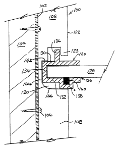
~n the first example (Figure 1), a rolled or folded steel angle
100 forms the aforementioned columnar support and is secured by
its back flange 102 to a timber wall-stud 104 by screws 106.
The front flange 1.08 of angle 100 has a cutout 220 opening into
its front face 122 and defining a downwardly-extending upper-lip
123. As illustrated, an extrusion 124 (preferably of aluminium)
is engaged within cutout 120, the extrusion being formed so as
to define a rectilinear shelf-slot 126 within which a shelf 128
(of glass, for example) can be fitted.
. ~ ,
The shelf-slot 126 is defined by parallel upper and lower walls
130 and 132 and by rear wall 134, upper wall 130 having an
integral thumb-strip 136 upstanding therefrom and lower wall 132
having an ridge 138 formed on the under surface thereof. Ridge
138 is formed so as to define a groove-like depression in the
inner face of wall 132 within which a hard-rubber pad-strip 140
is housed to cushion and retain .shelf 128 in slot 126. The
'WO 94/OZOSO _ ~ ~ ~ ~ 7 ~ ~ PC:T/AU93/003b3
i::;~ =:
cutout is formed so as to define an upper rear shoulder 142
against which the rear of upper wall 130 can bear.
Extrusion 124 is fitted into cutout 120 simply by offering it up
horizontally to the opening of cutout 120, tilting its front
face upwards until thumb-strip 136 passes under lip 123 and then
swinging its front face down until ridge 138 contacts the
forward part of the lower edge of cutout 120. In this example,
the weight of shelf 128 (once inserted into shelf-slot 126) is
borne, principally, by contact between ridge 138 and the lower-
front periphery of cutout 120 and by contact between the rear of
upper-wall 130 and shoulder 142. Some force, may also be borne
by contact between thumb-strip 136 and lip 123 and by contact
between rear-wall 134 and the back 144 of cutout 120. The lower
rear periphery of cutout 120 is of arcuate form (shown at 146)
to allow extrusion 124 to be swung into place while pivoting
around lip 123 (and allow it to be removed in similar manner).
In the second example (Figure 2), the columnar support is formed
by a folded or rolled steel channel 200 secured by its back 202
(shown in section) to a fixture 204 by screws 206. Each flange
208 has a series of cutouts 220 opening into its front face 222,
each cutout defining a downwardly extending upper lip 223 and an
upwardly extending lower lip 225. While each extrusion (224a,
224b and 224c) shown in this example is more complex than that
of the first example, it also defines a forwardly-opening shelf-
slot 226 having upper wall 230, lower wall 232 and rear wall
234. Upper wall 230 also carries a thumb-strip 236 but, in this
example, the thumb-strip is formed (in section) as a semi-
circular forward-facing hook. A groove is also formed in the
upper, face of lower wall 232 to carry a rubber cushion strip 240
but, in this example, the groove is of key--hole.shape so as to
retain the mushroom-shape strip 240. A downwardly facing groove
241 is formed along the under-side of the forward edge of upper
wall 230 to house a sealing or finishing rubber strip (not
shown) which bears against the upper face of, a shelf (not shown)
fitted in slot 226. Finally, the under-side of lower wall 232
carries a downwardly facing abutment-strip 245 positioned so as
WO 9x/02050 PCy"/A.U93/00363 ',;
to define a downwardly-facing slot 247 of sufficient width and
depth to accommodate lower lip 225.
In this example, an upper panel slot 246 is formed along the
upper-side of the forward edge of upper wall 230 to take the
lower edge of a cover-panel (not shown). A lower panel-slot 248
is formed along the lower-side of the forward edge of lower wall
232 to take the upper edge of a cover'=panel (not shown). The
depth of lower slot 248 is greater than that of upper slot 246
so that a panel can be readily fitted and removed between two
adjacent extrusions (as will be described in the third example) .
The three extrusions 224x, 224b and 224c of the second example
are shown in successive stages of being fitted into their
respective cutouts 220. In the first stage, extrusion 224a is
tilted so that thumb-strip 236 passes under and hooks around
upper lip 223 and extrusion 224a is then swung downwardly and
rearwardly about lip 223 (as shown by arrow 250). In the second
stage, extrusion 224b is swung down and rearwar.d_until its rear
wall 234 contact rear wall 244 of cutout 220, the extrusion
having been held up so that abutment-strip 245 clears lower lip
225 (as shown in the drawing). In the third stage, extrusion
224c is allowed to drop downwards (asa indicated by arrow 252)
until it rests on the lower edge of cutout 220 and abutment
strip 245 is lodged behind lower-lip 225.
Since the upper wall 230 of shelf-slot 226 defined by extrusion
224c is not supported by shoulder 242 of the cutout, the maximum
shelf-loading will be low. Modifications to the extrusion and
cutout of the second example (Figure 2A) can be made to provide
better support for'the shelf. ~In Figure 2A the same reference
numerals are used to identify the same parts as in Figure 2 and
two extrusions 224d and 224e are shown in two stages of entry
into cutouts 220. The essential difference between these
extrusions and those of Figure 2 is that the rear part 254 of
lower wall 232 is angled downwardly and forwardly so that it is
integrated with abutment strip 245 and so that its lower surface
forms a wedge br ramp with respect to the upper wall. This
results in the formation of a raised land-strip over the lower
~~-~''''v W~ 94f02050 ~ ~ s ~,~./AU93/Oa363 ,
7
lip 225 upon which the under-face of a shelf may rest. The
cutout of the modified second example, is essentially the same
as that of Figure 2 except that shoulder 242 is lowered so as to
provide support for the rear of upper wall 230 of shelf-slot 226
(as shown with the position of extrusion 224e).
The modified extrusion of Figure 2 is entered into the cutout
220 and swung down as- before but, in this case the under-face of
rear portion 254 of lower wall 232 will contact the top of lower
lip 225. To clear lip 225 extrusion 224d will have to be flexed
(as indicated by broken lines) to narrow the opening of shelf-
slot 226. Once in place, with rear wall 234 abutting the rear
face 244 of cutout 220 and with the upper rear of upper wall 230
tucked under (and in contact with) shoulder 242, the lower wall
1S 232 can be released so that abutment 245 snaps into place behind
lip 225.
Preferably, (i) the vertical distance between land 256 and the
lower extremity of groove 244 (which defines the upper edge of
shelf-slot 226) is substantially greater than the thickness of
the shelf to be accommodated, (ii) the vertical distance between
the level of land 256 and the level of the under-side of the
rear portion of upper wall 230 approximates the shelf thickness
and, (iii), the distance between most of the rear portion 254 of
2S lower wall 232 and the level of the rear of upper wall 230'is
substantially greater than the thickness of the shelf. This
allows the shelf to be easily entered into the shelf-slot 226 by
tilting the front of the shelf up so that the rear edge thereof
passes easily under the rear portion of the upper wall 230. The
shelf is then pushed home as it is lowered to the horizontal,
the shelf weight being borne principally by the rear of~ upper
wall 230 which is supported by shoulder 242 of the,cutout and by
land 256 which is supported by lower lip 225 and/or the region
of the cutout to its in~nnediate rear.
The extrusion 324 employed in the third example (Figure 3) is
very similar to that of Figure 2A except that the abutment 345
on the under-fAce of lower wall 332 is arranged to slope
upwardly and forwardly (the rear face of the lower lip 325 being
FCT/AU93/00363
i~VO 94/02050
g
correspondingly sloped). A land-strip 356 is formed over lower
lip 325 and performs the same function as described with respect
to land 256 in Figure 2A. While the rear portion 354 of lower
wall 332 is formed parallel with upper wall 330, it may also be
S sloped as in the extrusions of Figure 2A. The cutout 320 is
essentially the same as that of Figure 2A except. that the lower
rear edge 360 is sloped downwardly and~.rearwardly from a
substantially horizontal flat 362 for,,,~i~ied imanediately behind
lower lip 325. This combination of modifications with respect
to the example of Figure 2A allows extrusion 324 to be swung
downwardly into cutout 320 and fitted into place without having
to spring or flex the extrusion and, yet, the combination of the
shapes of the extrusion and cutout is such that the rear of
- upper wall 330 can be firmly supported by shoulder 342 of flange
308 of the channel-section columnar support 300 (shown in
perspective in Figure 3).
Like the example of Figure 2A, that of Figure 3 differs from the
examples of Figures 1 and 2 in regard to the fitting and
accommodation of the shelf (not shown in Figure 3). In these
earlier examples, all or part of the upper and lower shelf-slot
walls were parallel and were spaced apart by 'a distance just
sufficient to accommodate the thickness of the shelves employed.
With the third example, both the height of the front opening
(ie, the vertical distance between the lower face o.f groove 341
and land 356) and the height of the rear shelf-slot (ie, the
vertical distance between the rear portion of upper wall 320 and
the rear portion 354 of the lower wall) can be considerably
greater than the thickness of the shelf to be accommodated.
This allows easy entxy of the shelf into its slot 326. It is
important for the proper location and support of the shelf,
however, that the vertical distance between the. level of land
356 and the level of the rear of upper wall 320 approximates the
shelf thiekness. Thin double-sided adhesive tape may be used
between the shelf and either point (or both points) of contact
with the extrusion to hold the shelf into the shelf-slot. If
the tape is applied between the shelf and land 356, it can
usefully substitute for a cushion-strip (such as 140 0?': 240 ir_
Figures 1 or 2 respectively). As in the case of the example of
;'~v'=;. ~V~ 94/02050 ~ f ~ ~ ~ PCT/AU93/00363
9
Figure 2A, the weight of the shelf is mostly transferred to the
flange 308 via shoulder 342 and the top of lip 325 andlor the
flat 362.
The extrusion 324 of Figure 3 is provided with upper and lower
panel slots 346 and 348 which are essentially the same as panel-
slots 246 and 248 of Figure 2. In Figure 3, however, a panel
364 is shown fitted in place. As previously noted, panel 364 is
simply installed by holding it up to the extrusions and slipping
the upper edge into the lower panel-slot 348 of upper extrusion
324a, raising the panel until it abuts the top of slot 348,
swinging the lower edge of panel 364 until it is vertically
above and in-line with upper slot 346 of lower extrusion 324b,
and then dropping the panel into slot 346 so that it rests on
the bottom of this slot. If panel 364 is cut appropriately, it
will not drop out of slot 348 of extrusion 324a since the depth
of that slot is greater than that of slot 346 of extrusion 324b.
It will be appreciated that the examples of the invention
described above meet one or more of the desiderata set out as
objects of the invention. However, those skilled in the art
will also understand that many variations and modifications can
be made to the invention as disclosed without departing from its
spirit or scope as defined by the following claims. For
example, the cutouts can be made in the flanges of the columnar
supports any convenient fashion - by stamF:zg, forging, machin-
ing or cutting.