Note: Descriptions are shown in the official language in which they were submitted.
~~.~~8~~
CONNECTOR RECEPTACLE CONSTRUCTION
FOR ELECTRIC CIGAR LIGHTERS
This invention relates generally to electric cigar
lighters of the type commonly employed in automotive or
recreation vehicles, and more particularly to specialized
electrical connector constructions for energizing such
lighters.
The present invention relates more particularly to
improvements in the cigar lighter receptacle construc-
tion illustrated and described in applicant's expired
U. S. Patent No. 3,532,849 dated October 6, 1970, issued to
L. Horwitt, and entitled BIMETAL SHUNT FOR ELECTRIC CIGAR
LIGHTER. Reference is specifically made to the embodi-
ment of Fig. 4, and that of Fig. 5 of this patent.
The following additional patents are hereby made of
record and are believed to constitute a sampling of exist-
ing prior art in the field to which the invention relates:
U. S. Patents Nos.:
2,224,034 2,248,402 2,256,876
2,258,989 2,262,484 3,012,120
3,424,414 3,462,721 3,818,179
3,863,047 3,870,857 3,892,944
3,904,848 4,498,726 4,580,856
- 1 -
4,650,962 4,669,185 4,713,017
4,713,733 5,044,993 5,116,233
U. S. Patent No. 3,532,849, Figs. 4 and 5, disclos-
es cigar lighter constructions incorporating bimetal
shunts disposed in adapter shells (22, 22') mounted at
the rear of a lighter socket. In such constructions,
controlled flexing of the bimetal occurs unless an over-
heat condition arises in the socket, such as that result-
ing from a short circuit in either the socket or the
removable ignitor unit. In the event of malfunction, the
bimetal flexes sufficiently to electrically contact the
inner surface of the shell, thereby shorting the hot
lead to ground, and purposely blowing an in-line fuse so
as to minimize~the possibility of a fire.
The concept of the bimetal shunt circuit in a cigar
lighter socket has been widely accepted since the advent
of this patent, and devices embodying the basic concept
thereof have, as a result, enjoyed great commercial suc-
cess over the years, having been utilized in millions of
automotive vehicles and spanning a period of more than
two decades.
U. S. Patent No. 3,012,120 discloses an in-line
bimetal circuit breaker for installation at the rear of
a cigar lighter socket. As shown, only the "hot" elec-
trical circuit is controlled; the ground side of the
- 2 -
~~~o~~o
circuit remains intact after the breaker opens. As
opposed to Patent No. '849 discussed above, this patent-
ed construction did not "shunt" the hot side of the cir-
cuit during an overheat condition. Instead, it effective-
ly "interrupted" the circuit, as in the case of a fuse
or circuit breaker, and once such an interruption
occurred, the device was intended to be removed and dis-
carded, and a substitute unit installed. The device was
intended to fit existing cigar lighter base constructions,
as stated in col. 3, line 25 of the patent.
U. S. Patent No. 4,498,726 illustrates and describes
a connector for a cigar lighter socket of the kind hav-
ing a bimetal safety shunt similar to that of Patent No.
'849 identified above. The current carrying leads for
both the hot and ground sides of the cigar lighter cir-
cuit are embedded in a molded plastic or rubber plug,
and the plug is adapted to be pushed onto the central
terminal stud of the base, and in addition, to make
electrical contact with a screw shell carried by the
base. In this construction, the bimetal shunt is a part
of the cigar lighter socket per se.
U. S. Patent No. 3,462,721 illustrates and describes
a circuit breaker for a cigar lighter, in the form of a
capsule-like enclosure disposed at the rear of the light-
er socket, and containing a bimetallic circuit-breaker
type element. The breaker element is adapted to open the
- 3 -
hot side of the circuit in the event of overheating of
the socket or plug as a consequence of malfunction.
Provision is made for insertion of an elongate rod
through the socket from the front, to access the inte-
rior of the enclosure and enable the breaker mechanism
to be re-set, following actuation.
Referring now to others of the patents listed above,
three show another form of cigar lighter which has been
in widespread use in this country, for at least 15 years.
In particular, U. S. Patents Nos. 3,870,857 3,892,944;
and 3,904,848 contain generally similar disclosures
which describe cigar lighter structures that are espe-
cially adapted for manufacture and assembly by means of
automated equipment. At that time, the lighters repre-
sented by these three patents were referred to by the
assignee corporation, as "New Generation Lighters",
because of the advances that had been made with respect
to economy, ease of assembly, low failure rate, and the
ability to mass produce them in large quantities.
U. S. Patent No. 5,116,233 discloses a cigar light-
er construction utilizing a modified form of bimetal
shunt, somewhat similar to that of Patent No. '849 noted
above. In this patented design, the bimetal shunt is
disposed inside the lighter socket, and is indicated at
(17). Overheating of the pull-out igniting unit (not
shown), or of the socket itself results in the bimetal
- 4 -
contacting the inner surface of the metal socket wall
(18), in turn causing an in-line fuse (not shown) to
blow and thus minimize potential fire hazard.
The remaining patents mostly deal either with
bimetal circuit controllers, or else with various ter-
minal configurations associated with known cigar light-
ers and which were designed to facilitate making elec-
trical connection thereto. These are briefly discussed
hereinbelow, in chronological order.
Patent No. 2,224,034 shows an early lighter design
employing a bimetal element that is utilized solely as a
releasable, non-current carrying clip which is engaged
by a heating element cup when the lighter is actuated.
One side of the electrical circuit was established
through the metal socket of the lighter, while the hot
side (stud 28, Fig. 1) accepted a crimp-type lug connect-
ed to an electrical lead of the wiring harness (not
shown) of the vehicle's electrical system.
U. S. Patent No. 2,248,402 illustrates another type
of lighter construction in which a bimetal carried in
the socket of the device is employed to release a latch
that holds the ignitor plug as it is being energized. As
in the patent of the previous paragraph, the bimetal
itself is electrically out of the circuit, and merely
functions to sense that a predetermined heat level has
- 5 -
been attained by the heating element of the ignitor
plug.
U. S. Patent No. 2,256,876 illustrates a cigar
lighter construction employing two bimetals, one to
control latching and release of a spring-biased ignitor
plug, and a second bimetal which, in the embodiment of
Fig. 1, presses against the first with variable pressure
depending upon the ambient temperature prevailing at any
particular time. The objective is to minimize undesirable
fluctuations in the operation of the first bimetal latch
which would otherwise result from changes in its "start-
ing" position due to ambient temperature variations.
This patent was cited against U. S. Patent No. 3,863,047,
discussed below.
U. S. Patent No. 2,258,989 illustrates a temperature
sensor plug of especially compact design and which incor-
porates a bimetal member having multiple reverse bends
to the end that changes in temperature cause deflection
of the various branches of the bimetal in a manner where-
in they are cumulative, in order to obtain maximum de-
flection and sensitivity over the range of temperatures
being monitored. This patent was cited against Patent
No. 5,116,233 discussed above and which related directly
to a bimetal shunt for a cigar lighter.
U. S. Patent No. 2,262,484 illustrates an automatic
cigar lighter having a disk-like bimetallic element which
- 6 -
_ ~ ~i40a20
is disposed exteriorly of the socket o,f the lighter, and
which is mechanically flexed by insertion of the ignitor
plug, to close external switch contacts. Upon experienc-
ing heat from the heating coil of the ignitor plug, the
bimetallic element reverses its curvature and opens the
contacts. The bimetallic element itself is separate from
the current carrying part of the circuit, and as a result
carries no current per se.
U. S. Patent No. 3,424,414 illustrates a known cigar
lighter receptacle of a type which employed the usual
bimetallic latching fingers for engagement with a heat-
ing element cup of an ignitor plug. This patent was cited
against Patent No. '849 noted above.
U. S. Patent No. 3,818,179 discloses a cigar light-
er of a type having conventional internal bimetallic
fingers which engage a heating element cup of an ignitor
plug, and the socket of which has a rearwardly extend-
ing, generally cylindrical terminal post (27) for con-
nection to a source of power, not shown. The receptacle
configuration adapted to mate with this post is sim-
ilarly not shown.
U. S. Patent No. 3,863,047 describes a cigar light-
er having incorporated therein a bimetal shunt adapted
to respond to overheating within the socket by shifting
against a plate connected to the hot terminal, to blow a
fuse and minimize potential fire hazard. In one embodi-
_ 7 _
- ~ 2~~0~~~
ment, the bimetal is carried by the ground side of the
cigar lighter circuit, and is arranged to bridge the hot
side of the circuit upon experiencing overheating. In a
second embodiment, the bimetal is carried by the hot
terminal, and is arranged to contact the inner surface
of the cigar lighter socket upon experiencing overheat-
ing therein.
U. S. Patent No. 4,580,856 discloses a composite
clamp shell for a cigar lighter, constituted of two
pieces and including an integral spade lug type terminal
for connection to the ground side of an electric circuit,
as by means of a grounding push-on type receptacle.
Patent No. 4,669,185 contains a similar disclosure, hav-
ing been a Divisional Application based on the Applica-
tion which matured into Patent No. 4,580,856.
U. S. Patent No. 4,713,017 illustrates and describes
an electrical power outlet having a configuration some-
what similar to that of an electric cigar lighter socket.
The rear of the socket contains two flat electrical ter-
urinals for connection to an electrical circuit.
U. S. Patent No. 4,713,733 discloses a cigar light-
er having a socket with two rearwardly-extending spade
lugs for connection to an electrical receptacle (not
shown).
U. S. Patent No. 5,044,993 illustrates a power out-
let construction comprising a socket formation having
_ g _
- 2~408~0
rearwardly extending contacts in the form of flat ter-
minals, one of which is integral with the socket forma-
tion of the cigar lighter, having been stamped out there-
from. The resulting end portion of the one terminal is
folded back upon itself, to form a contact terminal com-
prising a double thickness of metal, for improved
strength.
While the devices disclosed in the patents noted
above have in some circumstances met with commercial
success, there is a continuous need to reduce overall
manufacturing costs, including steps toward either min-
imizing or eliminating manual labor. In many of the pat-
ented structures, this objective of cost has not been
adequately addressed.
Currently there exists a pronounced trend toward
use of plastics in the automotive field, especially in
the passenger compartment; accordingly, special atten-
tion must be given to potential sources of heat and/or
fire. In some of the patented cigar lighter construc-
tions employing a bimetal shunt, the bimetal was exposed
at the rear of the socket. Where overheating occurred,
resulting in actuation of the bimetal shunt, arcing at
the point of contact between the bimetal and its sur-
rounding grounded conductor was considered somewhat of
an electrical hazard.
_ g _
I i i
' CA 02140820 2005-02-04
Also, most prior lighter designs utilized specially
configured connectors for energizing the cigar lighter
through the socket. Until recently, relatively little
attention was given toward standardization of the socket
structures and their terminals, and as a consequence, a
multiplicity of divergent socket designs have been devised
and utilized over the years.
The present invention provides a cigar lighter
receptacle construction, comprising in combination: a) a
well part, a separate safety connector cartridge part, and
means for removably and disconnectably carrying the
separate safety connector cartridge part at the rear of the
well part, b) said parts having electrical connector means
constituted as engageable pairs of contactors, c) at least
one pair of said contactors comprising telescopic metal
cup-like formations providing electrical continuity
therebetween when the parts are connected, and d)
bimetallic means carried by the cartridge part, adapted to
electrically engage and short-circuit one contactor of a
pair of contactors of the connector means in response to
overheating of the well part.
The present invention also provides a cigar lighter
receptacle construction, comprising in combination: a) a
well part and a separate safety connector cartridge part
adapted to be disconnectably carried at the rear of the
well part, b) said parts having electrical connector means
forming engageable pairs of contactors, c) at least one
pair of said contactors comprising telescopic cup-like
formations, d) bimetallic means carried by the cartridge
part, adapted to shunt the connector means of the cartridge
part in response to overheating of the well part, e) said
cartridge part comprising an insulated body having a spade
lug projecting from one portion thereof, f) a bushing
mounted in said insulated body and being electrically
connected with said spade lug, g) said well part having a
-10-
i
CA 02140820 2005-02-04
projecting contact constituting one side of an electrical
circuit of said well part, h) said projecting contact being
received in said bushing in telescoping relation therewith
when the cartridge part is assembled to the well part, so
as to establish electrical continuity between the spade lug
and the well part's projecting contact.
The present invention further provides a cigar lighter
receptacle construction, comprising in combination: a) a
well part, a separate safety connector cartridge part, and
means for removably and disconnectably carrying the
separate safety connector cartridge part at the rear of the
well part, b) said parts having electrical connector means
constituted as engageable pairs of contactors, c) at least
one pair of said contactors comprising telescopic metal
cup-like formations providing electrical continuity
therebetween when the parts are connected, and d)
bimetallic means carried by one of said parts, adapted to
electrically engage and short-circuit one contactor of a
pair of contactors of the connector means in response to
overheating of the well part.
Still further, the present invention provides a cigar
lighter receptacle construction, comprising in combination:
a) a well part, a separate connector cartridge part, and
means for removably and disconnectably carrying the
separate connector cartridge part at the rear of the well
part, b) said parts having electrical connector means
constituted as engageable pairs of contactors, c) at least
one of said pairs of contactors comprising fractionally
interengaging telescopic and separable, electrically
contacting metal cup-shaped contact formations carried
respectively by said well part and said connector cartridge
part and providing electrical continuity therebetween when
the parts are connected, and interrupting said electrical
continuity when the parts are separated.
-11-
I i i
' CA 02140820 2005-02-04
The present invention also provides a cigar lighter
receptacle construction, comprising in combination: a) a
well part, a separate connector cartridge part, and means
for removably and disconnectably carrying the separate
connector cartridge part at the rear of the well part, b)
said well part having two electrical terminal portions
electrically insulated from one another and connected
respectively with two electrical circuits of the well part,
c) said separate connector cartridge part having two
projecting electrical terminals, electrically insulated
from one another, and extending outwardly from the
cartridge part, and d) means electrically connecting said
projecting electrical terminals of the separate connector
cartridge part respectively to said two electrical terminal
portions of the well part, thereby to enable the cigar
lighter receptacle construction to be energized through the
projecting electrical terminals of the cartridge part by an
electrical connector receptacle connected directly to said
projecting electrical terminals thereof, e) said projecting
electrical terminals of the cartridge part comprising two
spade lug terminals respectively.
The present invention also provides a cigar lighter
receptacle construction, comprising in combination: a) a
well part, a separate safety connector cartridge part, and
means for removably and disconnectably carrying the
separate safety connector cartridge part at the rear of the
well part, b) said parts having cooperable electrical
connector means constituted as engageable pairs of
contactors, one of said pairs being electrically insulated
from the other of said pairs, c) said removable cartridge
part comprising a plastic molding having a pair of
electrically insulated externally-accessible terminal means
molded into it I and said pair of insulated terminal means
being connected respectively to the pairs of contactors of
the connector means of the cartridge part.
-12-
I i i
CA 02140820 2005-02-04
The present invention further provides a cigar lighter
receptacle construction, comprising in combination: a) a
well part and a separate safety connector cartridge part,
b) means for disconnectably carrying the cartridge part at
the rear of the well part, c) said well part and said
safety connector cartridge part having electrical connector
means comprising engageable and disengageable pairs of
contactors, d) at least one disconnectable pair of said
contactors comprising telescopic separable cup-like
formations, and e) bimetallic means carried by the well
part, for shunting and electrically short-circuiting the
connector means of the cartridge part in response to
overheating of the well part.
As well, the present invention provides a cigar
lighter receptacle construction, comprising in combination:
a) a well part and a separate safety connector cartridge
part adapted to be carried at the rear of the well part, b)
said parts having cooperable electrical connector means
forming engageable and disconnectable pairs of contactors,
c) said cartridge part comprising a plastic molding
surrounding said engageable and disconnectable pairs of
contactors and having a pair of externally-accessible
terminal means, both of which terminal means are carried by
the cartridge part and which are connected respectively to
the said connector means of the cartridge part.
Also, the present invention provides a cigar lighter
receptacle construction, comprising in combination: a) a
well part having a grounding portion and an energizing
contact adapted respectively for engagement with cooperable
contacts of an ignitor plug to energize the same, b) a
safety connector cartridge carried at the rear of the well
part, said connector cartridge having a front face
juxtaposed to the well part, c) said connector cartridge
having a pair of spade lugs projecting from the rear face
thereof, said spade lugs having connector means for
-12a.-
I i i
CA 02140820 2005-02-04
connection respectively to said grounding portion and
energizing contact of the well part, and d) a bimetal shunt
connected to the energizing contact of the well part and
extending into the connector cartridge, said bimetal shunt
being activated in response to its being heated, a
connector means of one of the spade lugs being normally
disengaged from and engageable by the bimetal shunt in
response to heating thereof, thereby to effect a short
circuit from the said energizing contact to said one spade
lug.
The present invention further provides a cigar lighter
receptacle construction, comprising in combination: a) a
well part and a separate safety connector cartridge part
adapted to be carried at the rear of the well part, b) said
well part and said safety connector cartridge part having
cooperable electrical connector means forming engageable
and disconnectable pairs of contractors, c) said cartridge
part comprising a plastic molding surrounding said
engageable and disconnectable pairs of contactors and
having a pair of externally-accessible terminal means, both
of which are carried in the cartridge part and which are
connected through the said connector means of the cartridge
part, to the electrical connector means of the well part
respectively, so as to form a complete electrical circuit
to the well part.
The present invention alsc provides a cigar lighter
receptacle construction, comprising in combination: a) a
socket member having a grounding portion and an energizing
contact adapted respectively fcr engagement with cooperable
contacts of an ignitor plug, tc energize the same, b) said
socket member having a tubular side wall and a bottom
transverse wall formed integral therewith, said bottom
transverse wall being perpendicular to the tubular side
wall, c) a metallic heat shield. comprising a tubular member
having a side wall and a botton. transverse wall formed
-12b-
I i ~ i
CA 02140820 2005-02-04
integral therewith, said bottom transverse wall of the heat
shield being perpendicular to the side wall thereof and the
side wall of the heat shield substantially surrounding the
side wall of the socket member in spaced relation thereto,
d) said socket member transverse wall having a central
aperture and said heat shield bottom wall having a central
aperture which is substantially aligned with the aperture
of the socket member transverse wall, said walls being
juxtaposed and parallel, e) a threaded fastener extending
through said aligned apertures, for applying a clamping
force against and for holding the transverse wall of the
heat shield directly superposed on and fractionally engaged
with the transverse wall of the socket member whereby said
transverse walls are maintained in both intimate physical
frictional engagement and good electrical contact with one
another, f) said intimate physical frictional engagement of
the transverse walls restraining the heat shield against
axial movement with respect to the socket member.
The present invention further provides a cigar lighter
receptacle construction, comprising in combination: a) a
well part having a grounding portion and an energizing
contact adapted respectively for engagement with cooperable
contacts of an ignitor plug to energize the same, b) a
safety connector cartridge carried at the rear of the well
part, said connector cartridge having a front face
juxtaposed to the well part, and having a rear face, c)
said connector cartridge having a pair of spade lugs at the
rear face thereof, said spade lugs being connected
respectively to said grounding portion and energizing
contact of the well part, d) said pair of spade lugs
projecting beyond the rear of the surrounding surface of
said rear face, e) the perimeter of said rear face of said
safety cartridge completely surrounding both spade lugs at
those locations respectively where the lugs project from
said rear of the surrounding surface.
-12c:-
CA 02140820 2005-02-04
In the accompanying drawin~~s:
Figure 1 is a side elevational view of the improved
connector receptacle constructi~~n for cigar lighters.
Figure 2 is an axial sectional view of the
construction of Figure 1.
Figure 3 is a back end elevational view of the
construction of Figures 1 and 2.
Figure 4 is a front plan view of one of the spade lug
parts of the connector construction.
-12d-
~~.~08~0
Fig. 5 is a sectional view, taken on the line 5--5
of Fig. 4.
Fig. 6 is a rear plan view of the spade lug part of
Figs. 4 and 5.
Fig. 7 is a side elevational view of the spade lug
part of Figs. 4-6.
Fig. 8 is a front elevational view of the heat
shield part of the connector receptacle construction.
Fig. 9 is an axial sectional view of the heat
shield part shown in Fig. 8, taken on the line 9--9 of
Fig. 10.
Fig. 10 is a rear elevational view of the heat
shield part of Figs. 8 and 9.
Fig. 11 is a front elevational view of a contact
cup of the connector receptacle construction.
Fig. 12 is a view partly in side elevation and
partly in section, of the contact cup of Fig. 11.
Fig. 13 is a side elevational view of another of
the spade lug parts of the connector receptacle construc-
tion.
Fig. 14 is a rear elevational view of the spade lug
part of Fig. 13.
Fig. 15 is top plan view of the spade lug part of
Figs. 13 and 14.
- 13 -
~~.408~0
Fig. 16 is a front elevational view of the insulat-
ing or thermal cup part of the connector receptacle con-
struction.
Fig. 17 is a vertical section of the thermal cup
part, taken on the line 17--17 of Fig. 16.
Fig. 18 is a rear elevational view of the thermal
cup part of Figs. 16 and 17.
Fig. 19 is a front elevational view of the socket
member part of the connector receptacle construction.
Fig. 20 is a side elevational view of the socket
member part of Fig. 19.
Fig. 21 is a rear elevational view of the socket
member part of Figs. 19 and 20.
Fig. 22 is an axial sectional view of a contact cup
part of the connector receptacle construction.
Fig. 23 is a side elevational view of the assembled
receptacle or well part of the connector construction.
Fig. 24 is a side elevational view of the assembled
safety cartridge part of the connector construction, and
Fig. 25 is a view partly in side elevation and part-
ly in axial section, of a modification, wherein the safe-
ty bimetallic shunt is carried by the socket member part
of the connector construction.
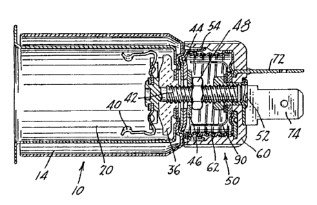
Referring first to Figs. 1 and 2, there is illus-
trated a cigar lighter receptacle construction consti-
tuted basically of two cooperable parts, a heat-shielded
- 14 -
- ~~408~~
socket part and a thermal or heat-insulated safety con-
nector cartridge part, said parts being separably con-
nected with each other. The heat-shielded socket or well
part is designated generally by the numeral 10, being
adapted to be mounted in a supporting panel 12 such as
the dashboard of an automotive or recreational vehicle.
The socket part 10 has an outermost heat sleeve or
heat shield 14, particularly illustrated in Figs. 8-10,
which is telescopically fitted within a transparent or
translucent glow ring 16, Fig. 1, the glow ring 16 being
pressed into a mounting hole in the supporting panel 12
and permanently retained therein in a known manner. An
electric light (not shown) is normally carried by the
heat shield 14, for illuminating the glow ring 16, also
in a known manner. The heat shield has a transverse end
wall 18 with a central aperture 19.
Disposed inside the heat shield 14 is a tubular
socket member 20 constituted as a drawn metal shell,
being particularly shown in Figs. 19-21. The socket
member 20 has an annular side wall 22 with lanced spring
fingers 24 (two in number, one being shown in Fig. 20)
that frictionally engage a cigar lighter ignitor plug
(not shown) of a type similar to that of U. S. Patent
No. 3,870,857 above identified, to normally frictionally
retain the ignitor plug in a storage position in the
socket member 20.
- 15 -
- ~~~~820
The entire disclosure of U. S. Patent No. 3,870,857
is specifically incorporated in the present application,
by reference.
At its inner end the member 20 has a transverse
wall 26, with a central aperture 28 that aligns with the
aperture 19 in the heat shield end wall 18. The wall 26
has three circumferentially displaced dimple formations
30 which are intended to be received in three of a plural-
ity of recesses 32 in the heat shield end wall 18, the
recesses 32 being twelve in number and being particularly
illustrated in Fig. 8. The recesses 32 are formed by
stamping, and corresponding nibs appear on the outer
surface of the wall 18, as in Fig. 10. In addition, the
transverse wall 26 of the member 20 has two lanced tabs
34, Figs. 19 and 21, which are received in corresponding
apertures (not shown) on a ceramic insulating base 36 in
the member 20, as described below. The tabs 34 are used
for positioning the base 36 in the socket member 20. In
some of the appended claims, the socket member 20 and
heat shield 14 are collectively referred to as a well
part.
The socket member 20 has a front radially extending
flange 38, Figs. 20 and 23, which is engaged by the glow
ring 16 and which positions the socket member 20 with
respect thereto and with respect to the dashboard 12.
Disposed in the socket member 20 is a U-shaped bimetal-
- 16 -
lic clip 40 adapted to cooperate with the heating ele-
ment cup (not shown) of a cigar lighter ignitor plug of
the type noted in Patent '857 referred to previously.
The bimetallic clip 40 is supported on a threaded con-
tact stud 42 (also called a projecting contact in the
claims) which functions as an electrical terminal that
is mechanically supported by the well part but is elec-
trically insulated therefrom. The insulating ceramic
base 36 that is located in the socket member 20 consti-
tutes an electrically insulating heat-resistant support
for the stud 42 and bimetallic clip 40. The base 36 has
a tubular boss which extends through the aperture 28 of
the transverse end wall 26 of the socket member 20, and
also through the aperture 19 of the transverse end wall
18 of the heat shield 14, as shown, the stud 42 in turn
extending through the boss of the ceramic base 36. There
is a centralizing washer 44 and an insulating washer 46
on the opposite side of the transverse wall 18 of the
heat shield 14, as shown, with a nut 48 securing the
stud 42, bimetallic clip 40 and base member 36 in posi-
tion.
During automated assembly of the heat shield 14 and
socket member 20, the three nibs 30 of the latter are
received in certain recesses 32 of the end wall 18 of
the heat shield 14, to achieve an automatic self-center-
ing of the two parts. The nibs 30 ultimately nest in any
- 17 -
~~~o~~o
set of three circumferentially spaced recesses 32 in the
heat shield's transverse end wall 18. As noted, the dis-
closed arrangement is such that the two transverse walls
18, 26 are substantially self-aligning with respect to
one another in a radial sense. The assembly of the sock-
et member 20 and heat shield 14 can conveniently be
accomplished by means of high-speed automated equipment.
In accordance with the present disclosure and as
shown in Figs. 1 and 2, there is provided an improved
safety connector cartridge or cartridge part 50 adapted
for connection to the rear of the well part comprising
socket member 20 and heat shield 14, which cartridge
part 50 has a threaded bushing 52 constituting a thread-
ed means, and the cartridge part 50 being capable of
being screwed on the stud 42 and held thereon so as to
establish electrical connection to the "hot" side of the
electrical circuit of the cigar lighter well part. This
hot side comprises the stud 42 and bimetallic clip 40.
In addition, a metal screw shell of the connector car-
tridge, to be described below, makes intimate electric
contact with the electrical "ground" side of the cir-
cuit, namely the socket member 20. The bushing 52 and
stud 42 constitute part of an electrical connector means
forming one pair of cooperable contactors.
In establishing the electrical connections of the
separate safety connector cartridge part 50 the well
- 18 -
21.4U8~0
part 14, 20 is provided with a substantially cylindrical
grounding cup or cup-like formation 54 shown in Fig. 22,
that is mounted on and electrically connected to the
transverse wall 18, and is held by the same nut 48 and
stud 42 which secure the bimetallic clip 40. The ground-
ing cup 54 has an outwardly flared lip 56', and a central
aperture 58 the walls of which are larger than the diam-
eter of the stud, so as to enable the grounding cup 54
to clear the stud 42. The grounding cup 54 mechanically
engages and is electrically connected with the transverse
wall 18 of the heat shield 14 of the well part.
Also, the separate safety insulated or thermal part
comprising the connector cartridge 50 has a plastic heat-
insulating and electrically-insulating cup 60 shown in
Figs. 16-18, having a ribbed outer surface as in Fig. 2,
which facilitates grasping the cup, either manually or
by means of automated equipment. The connector cartridge
50 comprises a steel screw shell 62, Figs. 11, 12, hav-
ing a bottom wall 64 with an aperture 66, the shell 62
being fitted into the plastic cup 60 so as to be in nest-
ing relation therewith. The plastio cup 60 has a trans-
verse bottom wall 68 with an aperture 70. The plastic
cup 60 carries two spade lug parts 72, 74 which consti-
tute exterior electrical terminals on the safety con-
nector cartridge part, the spade lug parts being elec-
trically insulated from one another and being respec-
- 19 -
tively shown in Figs. 4-7 and 13-15. The plastic cup 60
further forms with the screw shell 62 an annular recess
76, Fig. 17, extending between its transverse wall 68
and its lip 78. The recess 76 provides a clearance space
for the grounding cup 54, as can be seen in Fig. 2, such
that the grounding cup can be sandwiched between the
wall of the recess and the threaded screw shell 62.
The screw shell 62 and grounding cup 54 constitute
part of an electrical connector means forming a second
engageable pair of contactors, which are both cup-like
formations, and which telescope one within the other in
frictional engagement.
In manufacture of the separate safety connector
cartridge 50, the two spade lug parts 72, 74 are prefer-
ably molded into the bottom wall 68 of the plastic cup
60 at the time the plastic cup is formed, to provide
essentially a three-piece sub-assembly constituted of
the plastic cup 60, spade lug part 72 and spade lug part
74. The one spade lug part 72 shown in Figs. 4-7 has a
spade terminal and a base portion 80, constituting an
electrical connecting means for the spade terminal. The
base portion 80 has a plurality of nibs 82, shown as
being three in number, the purpose of which will be
explained below.
The second spade lug part 74 shown in Figs. 13-15,
also has a flat terminal and a base portion 84. There is
- 20 -
~~.4~J~~0
a hole 86 in the base portion 84, preferably of octagonal
shape as shown. The base portion 84 constitutes an elec-
trical connecting means for the spade terminal. The spade
terminals are substantially perpendicular to one another,
and are also substantially coextensive with one another.
The cup-like metal screw shell is illustrated in
detail in Figs. 11 and 12, and is seen to have multiple
recesses 88 in its transverse bottom wall 64. These
recesses 88 are intended to facilitate seating of the
screw shell 62 into the plastic cup 60 after the cup 60
and two spade lug parts 72, 74 have been molded as a
sub-assembly. When the screw shell 62 is pressed into
the cup 60, the three nibs 82 on spade lug part 72 are
received in three of the circumferentially spaced reces-
ses 88 in the transverse wall 64 of the screw shell 62.
The arrangement provided is highly effective in estab-
lishing a desired self-centering in a radial sense, of
the screw shell 62 with respect to the one spade lug
part 72; as a result, a high-integrity electrical con-
tact is provided between the spade lug part 72 and metal
screw shell 62, which is capable of handling the rela-
tively heavy current associated with cigar lighters of
the type intended to be used with the receptacle of the
present disclosure.
- 21 -
Referring again to Fig. 2, there is disposed in the
plastic cup a U-shaped bimetal shunt or bimetallic means
designated 90, and which is sandwiched between two spacer
washers, one of which is conductive and the other of
which is insulating. The shunt is preferably finger-like
in structure. There is also the threaded bushing 52,
constituting a threaded means, having at its inner end
an enlarged head, and the opposite end of the bushing 52
is headed over as in Fig. 2. This mechanically secures
the bimetallic means 90, the washers, shell 62 and spade
lug parts 72, 74 to the plastic cup 60; the bushing 52
is electrically connected to the bimetallic means 90 and
spade lug part 74. The bimetallic means 90 is arranged
to shunt the bushing 52 and stud 42 to the screw shell
62, which is in the cartridge part, in response to over-
heating occuring in the well part.
Further there are provided cooperable detent means
or structures on the lip 78 of the plastic cup 60 of the
connector cartridge 50, and on the transverse wall 18 of
the heat shield 14, for retaining the connector car-
tridge 50 in position once it has been screwed down to a
position wherein its lip 78 engages the heat shield 14.
In accomplishing the retention, the lip 78 of the plas-
tic cup 60 is provided with either one or two recesses
92, each having facing stop shoulders. In the case of
two recesses 92, they are displaced from one another by
- 22 -
- ~ ~1,~~8~p
180 degrees for example, and one or two projections 94
on the wall 18 of the heat shield 14 are formed by dimp-
ling. Figs. 8-10 show two projections 94, each projec-
tion having a crest portion and oppositely facing stop
shoulder portions. When the connector cartridge 50
becomes seated, the recesses 92 in the plastic cup 60
thereof are located so as to receive the nibs 94 respec-
tively on the heat shield wall 18. The slight mechanical
resistance that may be encountered in accomplishing the
seating is readily overcome by application of a somewhat
increased turning force to the connector cartridge, until
the recesses 92 arrive at the nibs 94. The nibs and
recesses retain the connector cartridge against inad-
vertent back off as might occur under conditions of
vibration over prolonged periods of time.
As particularly illustrated in Fig. 2, and as noted
above, the separate safety connector cartridge 50 is
screwed onto the well part comprising the socket member
and heat shield 14, in order to effect mechanical
20 retention of the cartridge 50. The edge of the screw
shell 62 preferably telescopes inside the grounding cup
54 of the well part, and with suitable dimensioning of
the parts, a press fit is established therebetween, re-
sulting in good electrical contact along a multiplicity
of points between the two surfaces. In a preferred form,
the engaging surfaces of the grounding cup 54 and screw
- 23 -
21~Q~~4
shell 62 can be made generally cylindrical, and include
the slight flare 56 which can be in the form of a sec-
tion of a cone on the outer telescoping part, i. e. the
grounding cup 54. As noted, the bushing 52, being thread-
ed, is used to pull up the separate connector cartridge
50 so as to cause forcible engagement between the screw
shell 62 and the grounding cup 54, as can be readily
understood. As a consequence, a reliable, high-integrity
electrical connection is established between the spade
lug part 72, through screw shell 62 and to the grounding
cup 54 at the rear of the well part. Potential problems
with poor or intermittent grounding of the well part
through the vehicle wiring harness (not shown) are thus
largely avoided. This is especially important where cigar
lighters of the type having plug-receiving wells, as in
the present instance,~are utilized with support panels
that are constituted of insulating materials such as
plastic. Plastic panels are widely used in modern auto-
motive vehicles in an effort to reduce cost and render
the vehicles light in weight, toward the ultimate goal
of increasing gasoline mileage.
The spade lug parts 72, 74 are preferably disposed
generally perpendicular to one another, and are dimen-
sioned and located to receive a standard push-on elec-
trical receptacle (not shown) of a type commonly used in
most automotive wiring harnesses in existence today.
- 24 -
- ' 214t~8~Q
Thus, the safety connector cartridge provides not only a
convenient, readily assembled integral bimetal shunt
circuit within a physically small package, but in addi-
tion, also provides an electrical (spade lug) terminal
configuration of a type which is directly compatible
with existing wiring harness connector receptacles,
essentially with no modifications or other type of ter-
minal adapters being required.
This is in contrast with many prior cigar lighter
constructions, in which for the "ground" side of the
circuit, reliance was placed on the electrical contact
between a metal dashboard and a metal clamping shell
that carried the lighter socket member. (See Patent No.
3,870,857, for example.) Also, various types of "hot"
terminal configurations have been employed, as can be
seen from the patents noted in the preamble of the pres-
ent specification. Until recently, standardization was
almost non-existent; both the "hot" and the "ground"
electrical circuits are established through the con-
nector cartridge 50, with a high degree of contact
integrity, and utilizing wiring-harness connector recep-
tacles of a type which have become standard in the auto-
motive industry.
Reduced manufacturing and assembly cost, as well as
improved reliability are thus realizeable.
- 25 -
2~4Q19~Q
A modified structure is illustrated in Fig. 25,
wherein corresponding components have been assigned ref-
erence numerals similar to that of the embodiment of
Figs. 1-24, and with the suffix "a" added where a some-
what modified component structure is utilized.
The modification of Fig. 25 illustrates a lighter
receptacle having a well part comprising a heat shield
14 and socket member 20, with the rear transverse wall
of the socket member being apertured and carrying the
stud 42, as in the previous embodiment.
There is provided an improved modified safety con-
nector cartridge 50a adapted for connection to the rear
of the well part, which cartridge 50a is capable of
being assembled thereto, and held in a position thereon.
A bushing 52a on the cartridge 50a is pressed onto the
rearwardly extending threaded stud 42 of the socket mem-
ber 20 so as to establish electrical connection to the
"hot" side of the cigar lighter circuit. The connector
cartridge comprises a plastic cup 60, and disposed there-
in is a metal screw shell 62 as in the previous embodi-
ment. The screw shell 62 makes intimate electric contact
with the electrical "ground" side of the well part.
Also, there is provided on the rear of the well
part comprising the socket member 20 and heat shield 14,
a cylindrical grounding cup 54 insulatedly mounted by
means of a nut 48 on the stud 42. The grounding cup 54
- 26 -
214Q8~~J
mechanically engages and electrically contacts the trans-
verse end wall 18 of the heat shield 14, and a firm press
fit is obtained between the screw shell 62 of the connec-
tor cartridge 50a and the grounding cup 54. As shown,
the lip of the grounding cup 54 is flared outwardly, ~o
as to telescopically receive the screw shell 62 of the
connector cartridge with a press fit.
The screw shell of the connector cartridge has an
apertured bottom wall that is fitted into the plastic
cup 60. As previously described, during manufacture of
the separate safety cartridge, two spade lug parts 72,
74 are molded into the bottom wall of the plastic cup
60, to form a three-piece sub-assembly.
A bimetal shunt 90a is carried directly by the stud
42, as opposed to the structure of the previous embodi-
ment where the bimetal shunt 90 was carried by the con-
nector cartridge 50. The mounting portion of the shunt
is sandwiched between the washers on the stud 42, as in
the prior construction. The bushing 52a is similar in
construction to the embodiment of Fig. 2, except that it
has a smooth bore, which enables the bushing (and car-
tridge) to be applied by a simple "push-on" operation,
in a direction axially of the stud. The bushing 52a
mechanically secures the washers, shell 62 and spade lug
parts 72, 74 to the plastic cup 60, and electrically
connects the spade lug part 74 to the stud 42. In opera-
- 27 -
~~.4~~20
tion, the bimetal shunt 90a is arranged to "short" the
stud 42 to the screw shell 62, located in the cartridge
part, in response to overheating occuring in the well
part.
As particularly illustrated in Fig. 25 and as noted
above, when the separate safety connector cartridge 50a
is pushed onto the well part, the edge of the screw shell
62 preferably telescopes into the flare of the grounding
cup 54, and a press fit is established therebetween,
resulting in good electrical contact along a multiplicity
of points between the two engaging surfaces. As a conse-
quence, the same reliable, high-integrity electrical
connection is established between the spade lug part 72,
through the screw shell 62 and to the grounding cup 54
at the rear of the well part.
The spade lug parts 72, 74 are arranged to receive
a standard push-on electrical receptacle (not shown) so
as to retain the advantages of the first embodiment as
regards utilization of standard wiring-harness type
receptacle configurations.
The following advantages are thus realizeable, with
the disclosed arrangements. Due to the self-centering
feature of the screw shell and one spade lug part 72,
achieved through the provision of the cooperable, nest-
ing nibs and recesses, there is obtained a high degree
of contact integrity, well suited to reliably handle the
- 28 -
relatively high currents normally associated with cigar
lighters, and substantially without the occurrence of
heating which might otherwise occur if relatively higher
contact resistances prevailed.
The essentially complete encapsulation of the bi-
metallic shunt by the surrounding connector receptacle
cartridge provides a high degree of safety, by isolating
and concealing from the exterior of the cigar lighter
well, any sparking which might occur as a consequence of
the bimetal shunt being actuated from excessive heat.
There is thus greatly reduced the possibility of exces-
sive heating of plastic wire insulation, or of a plastic
panel, as a consequence of this safety feature as
embodied in the present arrangement.
Also, with the disclosed constructions there is
realized a safety connector cartridge part which is
initially separate from a cigar lighter well part such
that the manufacture of the two parts can be greatly
simplified by means of automated assembly equipment. The
need for extensive manual labor is thus greatly reduced.
In spite of the ease of assembly, there is still
retained the reliability and functionality of the cigar
lighter and receptacle, the two being essentially uni-
tary in their final configuration, and capable for use
directly with an electrical wiring harness connector
- 29 -
:~.4Q~9~0
receptacle of conventional construction and of a type
which has become standard in the automotive industry
today, as noted above.
Variations and modifications are possible without
departing from the spirit of the invention.
Each and every one of the appended claims defines
an aspect of the invention which is separate and distinct
from all others, and accordingly it is intended that
each claim be treated in this manner when examined in
the light of the prior art devices in any determination
of novelty or validity.
- 30 -