Note: Descriptions are shown in the official language in which they were submitted.
~1~~8~6
-1-
A PRESS WITH A WINDOW-TYPE TENSION FRAME
Background of the Invention
The invention relates to a "window" type tension
frame for single-tier or multiple-tier presses (also
called multiple-stage presses), and more particularly to
such presses used for manufacturing chipboard,
f fiberboard, or other such wood-product boards and plastic
boards.
Description of Related Art
Single-tier and multiple-tier presses of the general
"window frame" type are known in many different designs.
This kind of design is used preferentially in multiple-
tier presses. The reason is that the I-beams or box
cross sections used in the vertical tension area of the
window frame provide a geometrical optimum moment of
resistance to the lateral shear that is mainly caused by
the orientation of the material being pressed.
Furthermore, it is the most cost-effective design due to
the possibility of flamecutting of plates and welded
plate construction. However, a press with a large number
of tiers (more than 20 tiers, for example) requires a
window frame with a great length due to the height of the
press. This large frame can not be worked mechanically
and is not transportable. The same applies in the case
of very wide single-tier presses with material mats of
approximately 6500 millimeters. This size press calls
for a press frame with outside widths being so large that
the weight per frame is about 120 metric tons.
Components with such large dimensions can no longer be
handled in transportation, especially over long
distances. In the case of very large and heavy multiple-
tier presses, the press frame construction is divided up
into transportable parts, for the above-mentioned
reasons.
214846
-2-
In known single-tier and multiple-tier presses of the
column design according to DE-AS 15 28 345, it is common
practice to prestress the tension columns in order to
prevent any loosening of the column nuts by the
constantly occurring repetitive stress from zero to Pm"
in cyclically operated presses. The prestress force in
the tension column must be greater than the Pm"~working
load in order to prevent any lifting apart at the contact
surfaces (nut and column offset) due to elongation by the
load, both in the upper chord and in the lower chord of
the press frame. Otherwise, especially where there are
acidic vapors (for example in the production of chip
boards or OSB boards) , galling occurs very rapidly at the
surfaces clamped together. This causes uncontrollable
changes in the accuracy of the pressing and heating plate
spacing, resulting in unacceptable variations in the
finished boards. In the case of very large and heavy
presses, the tension columns have to withstand the
pressing force "as a load," which means the prestressing
of the tension column requires a corresponding technical
effort and expense.
However, if the cross section of the tension columns
for withstanding the press forces is equal, the moment of
resistance to lateral shear - principally in the feed
direction of the press - is lower, and consequently the
moment of resistance to shear or flexure is greater by
about 5:1 in a welded frame cross-sectional design, and
thus generally more stable and resistant to shear. Also
assembly is by far more difficult, because the column
ends (upper and lower) have to be pre-stressed (shrunk
in) over the length held in the crosshead, so that the
clamped surfaces, in the case of protracted repetitive
stress produced in each working cycle from zero to Pm"~,
must always be in intimate contact. Nevertheless, it
happens in practice that, due to settling phenomena in
the thread, the prestress of the column shafts is
minimized, so that the junctions loosen at the clamped
surfaces, and this again leads to galling.
214046
._ _3_ ,
The consequences are poorer dimensional accuracies
in the finished boards and the press has to be
- disassembled and serviced. This is especially critical
at the transition from the column to the location where
the column shaft is clamped-in to the crosshead. At this
indentation the column is kinked by the flexural
deformation of the crosshead, which often, after years,
leads to failure due to the constant stress, especially
combined with galling. Consequently, to guard against
damage in most applications, such heavy column presses
are aftershrunk. The manufacturing costs and
consequently the invested costs are higher in comparison
with frame cross section design.
In the case of single-stage presses according to DE
OS 40 17 791 for application mainly as continuously
operating presses, tension shackles interlockingly
connecting the upper and lower crosshead are used for the
sake of better lateral accessibility. The shear forces
cannot be withstood by these designs. For this reason,
separate supporting designs are provided in these
presses. The force-transmitting surfaces between the
crosshead and the tension shackles are constantly in
engagement with one another in the case of continuous
operation, so that prestressing is not necessary, as it
is in the case of columnar designs for synchronous
presses. This concept is unsuitable technologically and
functionally for use in multiple-tier presses, since the
longitudinal and transverse shear forces as well as the
guidance functions for vertical or horizontal movements
cannot be assumed.
Ob-lectives of the Invention
One of the objectives of the invention is to create
a press of the tension frame type for an especially large
and heavy machine, which will have a modular press frame
system which can be assembled from a plurality of parts.
214084
-4-
Another objective of the invention is to have a press
having individual modules that will be easy to transport
and handle.
Another objective of the invention is to have a
modular press that when fully assembled will securely
accept the vertical press forces even under extreme
threshold load conditions at the mechanical junctions,
and which will be equipped with maximum usable moments of
resistance of the tension transmitting working parts to
the technologically caused, randomly oriented shear.
An advantage of the invention is to provide a press
that is made up of comparatively light individual
elements which is also easier to handle and transport,
because in comparison to the other window-frame cross-
sectional design, the individual elements have only 25~
of the weight thereof.
These objectives are achieved according to the
invention in that the tension frame design is made of
welded steel plates and created by means of anchor bolts
under tension. This arrangement prevents, with great
reliability, any pulling away or loosening at the joined
surfaces, so that the above-mentioned disadvantages do
not occur, because the collective load on the bias system
is approximately a power of ten less than it is in the
column press design.
Additional advantageous embodiments of the press
according to the invention will become apparent from the
detailed description given below. It should be
understood, however, that the detailed description, while
indicating a preferred embodiment of the invention, is
given by way of illustration only since various changes
and modifications within the spirit and scope of the
invention will become apparent to those skilled in the
art.
Summary of the Invention
The achieve the foregoing objectives, and in
accordance with the purpose of the invention, as embodied
and broadly described herein, a single-tier or multiple-
2i4~1~4G
-5-
tier press for the manufacture of chipboard, fiberboard
or other wood-product boards and plastic boards has a
lower crosshead and upper crosshead. Each crosshead is
provided with four force-receiving corner areas, which
are joined to two lateral tension shackles. A press
cross member, with pressing and heating plates, is
disposed on the lower crosshead. Also, the upper
crosshead is provided with a press cross member with
pressing and heating plates. Hydraulic jack pressure
devices are provided in the lower crosshead for raising
and lowering the pressing and heating plates mounted on
the lower press cross member.
The two lateral tension shackles are provided with
first and second clamping surfaces for interlockingly
joining with each of the four force-receiving corner
areas of the two crossheads, by first and second tension
bolts, to form a united clamping frame.
Brief Description of the Drawincts
The accompanying drawings, which are incorporated in
and constitute a part of the specification, illustrate a
preferred embodiment of the invention, and, together with
general description given above and the detailed
description of the preferred embodiment given below,
serve to explain the principles of the invention.
Figure 1 is a front elevation of the press according
to the invention;
Figure 2 is a side elevation of a longitudinal
section of the press of Figure 1;
Figure 3 is a detail of the left part of the press
shown by the section 3 in Figure 1; a
Figure 4 is a side elevation taken along the line
4-4 in Figure 3;
Figure 5 is a view taken along the line 5-5 in
Figure 3;
2140846
-6-
Figure 6 is an alternative embodiment of the press
shown in cross section; and
Figure 7 shows an alternative embodiment of the press
in a perspective view.
Detailed Description of the Preferred Embodiment
A press according to the invention is shown in Figure
1, viewed in a loading direction. As shown, the press is
a multiple-tier press, although the same arrangement can
be used for a single-tier press.
The press~is provided with an upper crosshead 2 and
a lower crosshead 1 connected under tension by tension
shackles 5. Upper press cross member 10 and bottom press
cross member 9 are disposed between the upper and lower
crossheads 1 and 2. The bottom press cross member 9 can
be raised and lowered by hydraulic jack systems 6 and 7
with pistons 6' and 7'.
The bottom press cross member 9 is equipped on its
upper side with a pressing and heating plate 11. The
upper press cross member 10 is equipped on its bottom
side with a pressing and heating plate 12. Additional
heating plates 13 of a simultaneous closing system 8 are
arranged in tiers for raising and lowering between the
two pressing and heating plates 11 and 12.
The lower crosshead 1 has a projection 3 and the
upper crosshead 2 has a projection 4. These projections
establish the width of the press. As shown in Figure 2,
the thickness of the crossheads 1 and 2, disposed in
tandem, establish the length of the press. The length of
each crosshead 1 and 2 is established by reinforcing ribs
14 connecting the two plates that comprise the crosshead.
As shown in Figure 5, the rib 14 in crosshead 2 is welded
to the plates 2a and 2b.
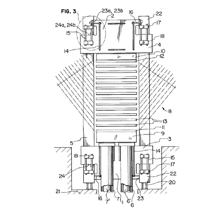
Figures 3-5 show the details of one corner of the
frame; shown is the connection between tension shackle 5
and crosshead 2. This illustrates an example of the
joint that is used in each connection between the two
2140846
_7_
tension shackles 5 and the crossheads 1 and 2, as shown
in Figures 1 and 2.
Tension shackles 5, configured in this example as I
beams, are connected between the crossheads 1 and 2.
Alternatively, the tension shackles 5 can also be made
with a box cross section.
As shown in Figures 4 and 5, the end of each tension
shackle 5 is provided with welded-on cross plates 25,
overlaid plates 22, and clamp cross members 17. The
cross plates 25, overlaid plates 22, and the clamp cross
members 17 provide an arrangement for locking the ends of
the tension shackle to the crossheads 1 and 2.
Over the tension shackles 5 thus configured, the two
overlaid plates 22 are placed so that their clamping
surfaces 24a contact the horizontal clamping surfaces 24b
of the outwardly reaching projections 4.
Tension bolts 15 are used to vertically hold together
the crosshead 2 and tension shackle 5 by the clamping
together of the cross piece 17 welded to the overlaid
plates 22 and the cross piece 18 welded on the projection
4.
For providing horizontal tension and engagement of
the tension shackle's vertical clamping surfaces 23a with
the vertical clamping surface 23b of the projection or
nosing 19, overlaid plates 22 are held in engagement with
crosshead 2 by means of tension bolts 16 connected
between one of the crosslinks 25 and one of the
stiffening ribs 14.
With this arrangement provided at each connection,
it allows the two crossheads 1 and 2 to withstand the
pressing force applied when the press is operated.
With each side of the tension shackles 5 clamped to
the crossheads 1 and 2 by the arrangement described
herein and illustrated in Figures 1-5, the tension anchor
bolts 15 and 16 hold the clamping surfaces 23a, 23b, 24a,
24b together. Welds are applied to the clamping surfaces
to provide additional support to allow the frame to
withstand the press forces. The press itself stands on
a base 20 which is supported by a foundation 21.
2140846
_8_
The "window" frame design according to the invention
provides the press with a tight clamping design. For
this purpose the bias force of the vertical tension bolts
15 needs only to be designed for the inherent weight of
the upper crosshead 2, the upper cross member 10, the
upper pressing and heating plates 12, the simultaneous
closing system 8, the hydraulic pistons 6' and 7', the
material being pressed, and the dynamic mass forces.
It is important that the bias force be made such that
even in the case of maximum flexure of the upper and
lower crossheads 1 and 2 , the mechanical positions of the
tension shackles 5, provided for guiding purposes with
respect to one another at the vertical clamping surfaces
23a and 23b, will remain free of free play.
In an alternative embodiment shown in figure 6, if
two of the tension shackles 5 are made up with a
rectangular box girder shape 30, their vertical guiding
tracks 90° apart can serve as guiding tracks for the
lower press crossbeam 9 with pressing and heating plate
11 and additional plates 13 for the vertical fast
movement, while the opening and closing movement of the
press is centered and the lateral thrust due to the
nonrandomly spread material will be compensated
lengthwise and crosswise during compression under maximum
press force.
Figure 7 shows an alternative embodiment of the
invention (an embodiment without a simultaneous closing
system), wherein the same reference characters have been
used to identify parts similar to the first embodiment of
the invention. In this embodiment, crossheads 1' and 2'
are provided with a quadrilateral shape. This embodiment
also uses tension bolts 15 and 16 to clamp the crossheads
1' and 2' to the tension shackles 5, however, the tension
bolts and their associated crosspieces 17, 18, and 25
have been omitted from the figure for clarity.
It will be understood that various modifications in
the form of the invention as described herein in its
preferred embodiment may be made without departing from
214084
_9_
the spirit thereof and of the scope of the claims which
follow.