Note: Descriptions are shown in the official language in which they were submitted.
Description
Fatigue Analysis and Warning,~stem
Technical Field
This invention relates generally to
evaluating frame and loading characteristics for a
large work machine, and more particularly to
evaluating frame and loading characteristics in
response to pressure signals of sensors located
between the load and the ground engaging portion of
the machine.
Background Art
Large off-highway trucks carry large
quantities of ore or overburden over haul roads in
open pit mines or in other applications. The
conditions in which these trucks are used are
typically severe. The haul roads may have ruts,
potholes, or large rocks interspersed throughout the
work site and must be negotiated by the off-highway
trucks. Mine managers attempt to reduce the stresses
applied to the trucks by regularly maintaining the
haul roads. Many of the obstacles are dependent on
the location of the work site or weather conditions
and cannot be completely eliminated.
Given the huge weights of materials being
hauled, these obstacles can cause the frame of a truck
going over the obstacles to twist. These twisting
moments cause the truck structural components to fail
over time.due to metal and weld fatigue. The more
severe the work environment, the shorter is the
expected fatigue life of the structural components.
Load imbalances may also contribute to
fatigue failure by causing similar twisting actions of
the truck frame and other structural components. Load
imbalances can cause further damage during dumping of
i
-2-
the material since the weight is concentrated on the
rear of the truck frame when the dump body is raised.
The problems associated with truck overloading and
load imbalance is therefore exacerbated during
dumping.
These trucks represent huge investments and
cause great losses of productivity if they require
maintenance at unscheduled times. Certainly, one of
the most critical aspects in the performance of
complex machines such as mining trucks is the
structural integrity (e. g., fatigue life) of the major
load carrying elements such as the main frame, dump
body, and the suspension undercarriage components. It
is therefore critical for proper work site management
to understand when a truck is being used such that
expected life is being reduced. Actions can then be
taken to,correct whatever is causing the reduction in
expected fatigue life of the structural components.
Prior systems have relied upon experience
and rough approximations to predict frame life and
roading or loading conditions that may cause frame
damage. This practice introduces considerable
subjectivity into the system and results in the
vehicle being operated abusively without knowledge of
the extent of potential damage or the causes of
damage. It is a somewhat daunting task for a
- structural design engineer or structural analyst to
predict with high confidence the life of such complex
I structures when they are operated in a wide variety of~
environments.
Knowledge of potentially damaging events
would be useful to not only work site managers, but
also the driver of the truck and the operator of the
machine loading the truck. For example, the driver
could slow the truck down before reaching a particular
~~.~~8~~
-3-
part of the haul road if during the previous trip he
went over a bump and was notified that this caused an
event contributing to a shortened frame life.
Similarly, if the operator of the machine loading the
truck is notified that the load is unbalanced, then he
can strive to improve balance by placement of
subsequent loads. Furthermore, mine management can
use such data to recognize operator abuse of the truck
and to improve maintenance of the haul roads. For
example, if the mine manager recognizes that the
number of potentually frame damaging events is
increasing, he can infer that haul road quality is
decreasing so that mauntenance should be increased.
Other systems, such as the one disclosed in
U.S. Patent No. 4,635,739 issued to D. Foley et al. on
Jan. 3, 1987, have shown that strut pressure can be an
accurate indicator of payload. The apparatus
disclosed therein includes an electronic control that
monitors each of the strut pressures, compensates for
various inaccuracies introduced by load distribution
and vehicle attitude, and correlates this information
into actual payload. This payload unformatuon allows
the truck to be operated efficuently near its maximum
capacuty without promoting undue vehicle wear. An
overloaded vehicle hastens tire and frame damage.
While systems of this type provide accurate
indications of payload, they are incapable of
identifying events that are suffuciently severe to
contribute to frame damage. Payload monitors can
provide undications that the load in the truck is
above or below its rated capacity; however, frame
damage depends upon many other factors and is caused
primaruly by situations involving uneven stresses
rather than simply overloadung the truck. Even though
a truck is loaded below capacity, it can still undergo
n L:
' . ' .
-4-
events contributing to frame failure. Such damage
typically occurs by such events as hitting potholes or
ruts or dumping an unbalanced load.
No system available in the prior art
correlates suspension and/or load characteristics to
the estimated life of the frame. The frame of
vehicles of this type are typically complex welded
structures and frame damage cannot be correlated
directly to payload alone. Due to the complexity of
the frame, damage can occur in any of a variety of
areas and different types of events can cause damage
to different areas. Prior art systems have also not
accumulated frame stress data to indicate trends in
work severity.
The present invention is directed to
overcoming one or more of the problems as set forth
above.
Disclosure of the Invention
The invention avoids the disadvantages of
known truck monitoring systems and provides a device
capable of providing indications of frame stresses
occurring during operation and their expected affect
upon expected frame life. The subject invention also
provides warnings to the operator and/or to mine
management personnel that significant frame stresses
have recently occurred or are expected to occur
shortly.
Tn one aspect of the invention, an apparatus
is provided including a ground engaging portion, a
frame connected to the ground engaging portion, a
plurality of pressure sensing devices, and a processor
that receives the pressure signals and responsively
estimates one or more strains occurring on the frame.
,.-.,
-5-
Frame stress is quantified in response to the pressure
signals and the strain estimates.
Tn another aspect of the present invention,
a method for analyzing frame damage during operation
of a machine is provided. The method includes the
steps of building a system of equations describing the
relationship between strut pressure and frame damage,
measuring the amount of pressure in a plurality of
sensing devices on the machine, and'estimating frame
damage in response to the measured pressures.
The invention also includes other features
and advantages which will become apparent from a more
detailed study of the drawings and specification.
Brief'Description of the Drawings
Far a better understanding of the present
invention, reference may be made to the accompanying
drawings, in which:
Fig. 1 is a diagrammatic view of an off-
highway truck and shows the location of critical
suspension components;
Fig. 2 is a block diagram of a preferred
embodiment of an apparatus for monitoring vehicle
parameters;
Fig. 3 is a diagrammatic view of finite
elements of a main frame for an off-highway truck;
Fig. 4 is a diagrammatic view of finite
elements of an A-frame/banjo housing for an off-
:~
highway' truck;
Fig. 5 is a diagrammatic view of finite
elements of a dump body for an off-highway truck;
Fa.g. 6 is a vector diagram of a generic
elastic body;
Fig. 7 is a schematic illustration of a
front strut for an off-highway truck;
z~~o~~~
-6-
Fig. 8 is a schematic illustration of a rear
strut for an off-highway truck;
Fig. 9 is a model schematic for use in
connection with one embodiment of the present
invention;
Fig. 10 is a series of strain and pressure
values graphed as a function of time;
Fig. 11 illustrates relationships between a
rainflow histogram and a load life graph;
Fig. 12 illustrates a method of obtaining a
Fatigue Equivalent Load Analysis (FELA) value;
Figs. 13a and 13b illustrates a flow chart
for an algorithm used in connection with an embodiment
of the present invention;
Fig. 14 is a graph of historical composite
FELA values;
Fig. 15 illustrates a flow chart for an
algorithm used in connection with an embodiment of the
present invention;
Fig. 16 is a graph of strut pressures during
a roading loaded portion of an off-highway truck
hauling cycle;
Fig. 17 is a graph of strut pressures during
the loading portion of an off-highway truck hauling
cycle; and
Fig. 18 is a graph of strut pressures during
dumping portions of an off-highway truck hauling .
cycle.
i,~,i i
Best Mode for Carryina dut the Invention
The drawings show a preferred embodiment of
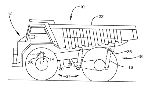
the present invention. Fig. l shows the apparatus 10
as applied on an off-highway mining truck l2. It
should be appreciated, however, that the present
invention is equally applicable to many types of work
machines, such as track-type tractors, wheel-type
loaders, motor graders, etc. The truck used in the
preferred embodiment has two front and two rear struts
14,16 which are the independent, self-contained, oil-
s nitrogen type commonly known in the industry. It is
sufficient in the understanding of the instant
apparatus to recognize that the pressure of the fluid
is indicative of the magnitude of load applied to the
strut and that wide swings in strut pressures are
normal and even expected during certain portions of a
haul cycle. The haul cycle known in the art typically
includes a loading portion, a roading loaded portion,
a dumping portion, and a roading empty portion.
The load carrying portion 18 of the truck
includes a main frame 20 and dump body 22. The dump
body 22 is connected to the main frame 20 by a pivot
pin and a hydraulic cylinder. The contents of the
dump body 22 are removed by controllably pressurizing
the hydraulic cylinder to effect pivotal movement of
the dump body 22 about the pivot pin. In the
transport mode, the cylinder is not pressurized and
the weight of the dump body is transferred to the
frame through the pivot pin and a support pad fixed to
the frame 20.
The off-highway truck 12 further includes a
ground engaging portion 24, such as a tire, and has
two axles with one of the independent, self-contained,
oil-nitrogen suspension struts 14,16 connected to each
wheel. 'The rear axle consists of an A-frame which
connects to the axle/differential housing known as the
banjo housing (shown more clearly in Fig. 4). This
assembly is connected to the main frame with a
spherical joint, a sway bar, and the two rear struts
at the trailing end of the banjo housing.
_g_
During loading of the truck, as the payload
increases, the load carrying portion 18 is displaced
in a direction toward the ground engaging portion 24.
Each rear strut 16 begins to compress while the A-
frame moment arm pivots about the spherical joint.
Th.e rear strut pressure is related to the reaction
force between a work surface and the ground engaging
portion 24.
The front and rear independent, self-
contained, nitrogen-over-oil suspension struts 14,16
provide shock isolation and damping between the
unsprung masses and the main frame 20. This type of
suspension arrangement is widely used on mining
trucks.
The front strut 14 transmits spring and
damping forces into the main frame 20 from the front
tire. The body of each front strut 14 is bolted to
the truck main frame 20 so that translational motion
occurs along the fixed axis of the cylinder. This
arrangement is commonly referred to as a sliding
pillar. Due to this mounting arrangement and the line
of action of the ground input forces, the front strut
carries a moment which in turn leads to intermittent
stick-slip behavior. The front strut is depicted
schematically in Fig. 7. The rear strut component
model, which is shown schematically in Fig. 8,
includes all of the same effects with one notable
exception - the rear strut carries no moment since it
is mounted'with spherical bearings at both ends of the
cylinder. Hence, there is no stick-slip effect on the
rear strut.
Of course, the above conditions apply to a
particular truck design. It is understood that other
chassis configurations may be used. Furthermore, the
present invention is not to be limited to off-highway
-9-
trucks. As described above, the invention is equally
applicable to any machine for which it is desirable to
understand frame stresses.
A block diagram illustrating certain
electrical and electronic portions of the apparatus 10
is shown in Fig. 2 and illustrates pressure sensors 26
for each of the struts which deliver a plurality of
signals each having a value responsive to the internal
pressures of a respective suspension strut 14,16. The
plurality of pressure sensors 26 are of a type
commercially available and are respectively associated
with the two front struts and the two rear struts.
Each of the pressure sensors 26 delivers an analog
signal proportional to the magnitude of the pressure
of the respective strut to an interface module 28.
Data from the pressure sensors 26 and other
parameter sensors is gathered by the interface modules
28 that communicate the data in digital form by a
high-speed communication ring 30 to a main module 32,
where data is manipulated and stored until downloaded
to an off-board control system 34. It should be noted
that while this describes the preferred embodiment,
other suitable hardware arrangements may be used
without deviating from the invention.
Data and warnings are also transmitted from
the main module 32 to a display module 34 for
presentation to the operator in the form of gauges and
i warning messages. In'the preferred embodiment, the
display'module 34 is the standard gauge, warning, and
information delivery package available on machines of
this type. During normal operation, gauge values are
displayed on the display module 34. During out-of-
spec conditions, alarms and warning/instructional
messages are also displayed. A keypad is provided to
allow entry of data and to allow system-level requests
~1~~0~~~
-10-
in the absence of a service tool. A message area is
provided and includes a dot-matrix LCD to display text
messages in the memory-resident language and in SI or
non-SI units. A dedicated backlight will be employed
for viewing this display in low ambient light
conditions. The message area is used to present
information regarding the state of the machine.
By way of example, warning lights and/or
warning messages are displayed to the operator by the
display module 34 whenever damaging stresses occur or
when damage to the frame is anticipated. For example,
a warning light is illuminated when a significant
stress is applied to the frame thereby informing the
operator that his operation of the machine should be
modified or he should notify the mine manager of poor
haul road conditions. Similarly, a message is
displayed on the dot-matrix LCD to inform the operator
that the load is positioned such that dumping could
cause frame damage.
While the main, interface, and display
modules 32, 28, 34 comprise the baseline machine
monitoring system, additional on-board controls 36,
such as engine and transmission controls, are
typically integrated into this architecture via the
communication ring 30 in order to acquire the
additional data being sensed or calculated by these
controls and to provide a centralized display and
storehouse for all on-board controls' diagnostics.
Two separate serial communication lines~are
provided in connection with the main module 32. One
line 38, intended for towline uploading and
downloading of data to a service tool, will feed two
serial communication ports, one in the operator
compartment and one near the base of the machine. The
second serial line 40 feeds a separate communications
,r:.,
21~~U8~8
-11-
port intended for telemetry system access to allow the
main module 32 to interface with a radio system 42 to
transmit machine warnings and pressure and/or strain
data off-board and to provide service tool
capabilities via telemetry. Thus the main module 32
is capable of communicating with an off-board system
44 via either a direct, physical communication link or
by telemetry. In the preferred embodiment, the off-
board system 44 includes a microprocessor and is
advantageously a commercially available work station;
however, other types of microprocessor-based systems
capable of sending and receiving control signals and
other data may be used without deviating from the
invention.
Turning now to the method of obtaining
values indicative of frame stress in response to
sensed parameters, a matrix of equations :i.s required.
In the preferred embodiment, the matrix of equations
is defined as follows:
LA] {f} _ {e}
where: [A] is the matrix of equations defining
pressures as a function of stresses;
{f} is a nx1 matrix of unknown stresses; and
{e} is a mxl matrix of known pressure values
obtained from the pressure sensors 26.
Since one of the objects of the disclosed apparatus is~
to obtain data indicative of frame stresses without
having numerous strain gauges located at various
places around the vehicle and further because
suspension strut pressure signals are already
available on the machine for reasons such as payload
monitoring, it is advantageous to manipulate the
.~1~084~
-12-
equations such that the strain values can be obtained
from the already available pressure signals. To
obtain the unknown stress matrix {f}, the [A] matrix
must be manipulated to obtain a [B] matrix where:
[B] - ([A]T[A])-1[A]T.
Thus:
to {f} _ [B] {e}
As is well-known in the art, this is referred to as
the least-squares technique for solving a system of
equations. If the inverse of a matrix is obtained,
some of the resulting equations may not provide valid
results. This effect can be minimized by known
methods of insuring that the equations are
independent. The more independent the equations in
the [A] matrix, the more likely that the equations of
the [B] matrix will provide valid results. Some of
the known methods of ensuring independence include
examining the slope values of the matrix, the
correlation of matrix values, the row dot products of
slope values, the column dot products of slope values,
etc. Equations that are dependent on other equations
may be eliminated or a single equation may be written
to replace two or more similar equations. Ultimately,
the necessary level of independence is determined
empirically and by trial and error to ensure that~the I
equations used provide valid results.
In the preferred embodiment, the
coefficients in the [A] matrix are empirically
determined. The initial equations and coefficients
are selected by using a multilinear regression of
experimental load and strain data. The data utilized
-13-
in the derivation of equations is provided by the
pressure sensors 26 and a series of rosette strain
gauges capable of providing two-dimensional strain
data. One of the strain gauges is located in each of
the areas of interest on the frame. Advantageously,
many strain gauges are located at numerous positions
about the main frame 20. The empirically determined
equations are then examined and only those having a
significant correlation are selected for the next
steps.
The selected equations are then further
manipulated by the above described methods to arrive
at a [B] matrix having valid equations. The system of
equations used in the present invention preferably
include four different pressure signals and six
different strain locations positioned about the main
frame 20. The pressure signals are taken from each of
the four suspension struts 14,16 and the strain
locations are selected as being located at the
fore/aft transition casting, the dead chicken casting,
the center cross tube transition casting, the base
pedestal area, the banjo housing, and the body pivot
casting.
It should be understood, however, that the
present invention is in no way limited to this number
or location of strains. In fact, for each type of
machine or frame, the parameters required to provide a
useful [B] matrix will vary and must be empirically
determined'based on experimental data relating loads
to frame stresses. The present invention should
similarly not be limited to the main frame; the same
methods are equally useful for virtually any
structural component for which fatigue life is an
important consideration.
~~.40848
-14-
In an alternative embodiment, the [A] matrix
is obtained through a three dimensional mathematical
model of the work machine developed to simulate
transient structural deformation and suspension
response. The model incorporates compliant (finite
element) representations of the truck frame, dump
body, and rear axle housing into a dynamic mechanical
system simulation model.
In the model, frame acceleration, axle
housing elastic deformation (strain), and suspension
response (strut pressures and displacements) are
correlated with measured data from pressure sensors
and a plurality of accelerometers located on the
frame. The accelerometers (not shown) are input to
the system via the interface module in a manner
similar to the pressure sensors 26. In the preferred
embodiment, the forward accelerometer location is near
the middle of a forward transverse beam which is under
the engine. This location is on the left-to-right
centerline of the truck. The rear location is near
the dump body rear pivot point on the left hand side
of the trunk.
In this embodiment, the flexible body
components are included in a large motion, multi-
component, integrated, system dynamic analysis
program. The equation of motion formulation is the
governing mathematical representation of the flexible
body component motion reflecting the integration of
'''' ~ ~ large global displacement with linear structural
deformation. The legitimacy of the mathematical
formulation is determined empirically.
The term "flexible body" as used herein
refers to an entity that can experience large spatial
motion while deforming elastically. The dynamic
equations for a flexible body represent the motion of
-15-
a set of node points defined relative to a body
reference coordinate system which can translate and
rotate in a global inertial reference frame. The
fundamental elastic relationships are defined by the
node coordinates and the mass, damping and stiffness
matrices acquired through finite element modeling of
the structure. The extension of these linear
relationships to incorporate large nonlinear motion
proceeds as follows.
Consider the generic elastic body in Fig. 6.
Given an arbitrary node, Ni, which prior to deformation
has body referenced position coordinates s~~ and has
deformed in translation by w~~~ relative to s~~, the
global position, u~~, is given by:
urn . r + A(s y + W .)
where r is the global position of the body reference
frame and A is the rotation matrix which maps vectors
in the body reference to the global reference.
Differentiating with respect to time produces the
global nodal velocity, i.e.
tit ° r + A(s~~ + w~~~ + Av~e
Furthermore, given an arbitrary body referenced
vector, v, it can be readily shown that
Av = A(w~xv) + Aww
which represents a mapping into the global system of
the body angular velocity, w~, crossed into the
vector, v. The tilde symbol in the latter form is the
., ,, .. . " , ; ,. .. .,: .. ,.,.., ,..,
.. ~ ~14fl8~8
-16-
skew symmetric matrix of w' terms which produces the
cross product when post-multiplied by v.
Applying this relation yields the following for rsr~:
ur r + AIw'(s'r + wir) + wire
It is desirable to have the nodal velocity defined in
the body system prior to defining momentum because the
finite element matrices are body system defined. Pre-
multiplying the above equation by the transpose of the
rotation matrix yields the body system nodal
translational velocity:
ri~rr -_ ATi' + c3ysri + w'r~ + w'r
Now consider the body system nodal rotational velocity
which is given by the less complicated relation:
u~ = w~ + r'v~
r. r.
for which the subscript r indicates rotation.
For simplicity, translational and rotational vector
quantities are combined as:
uy=~uy~
wri = ~
Making no assumptions about the structure of the
finite element mass matrix, the nodal momentum vector
is, in general, a function of all nodal velocities.
Therefore, for a finite element model having n nodes,
the body system momentum for node N~ is given by:
.I:,......:\.
-17-
n
p ~r = E Mt~.u J
j=1
where M,J represents the partition of the mass matrix
with rows corresponding to node Nr and columns
corresponding to each node NJ, The nodal inertial load
is obtained by differentiating in time the momentum,
however, the momentum must first be referenced to the
inertial coordinate system.
Introducing a 6 x 6 rotation matrix A8 as:
- rAO,
As O JA
the global nodal momentum for node Nr becomes:
n
Pr -_ A J~lMrru ~
Differentiating and applying the previously defined
relation for .ti yields:
13r _- dPr -_
dt
n n
~~8 w rx E MUu ~ +. E M~ du J
j=1 j=1 dt,
:, , ;
Differentiation of the body referenced nodal velocity, uJ
is straight forward and will not be performed here.
The nodal inertial load, f~r~, referenced to the body
~~.4~$~~
-18-
orientation is obtained by mapping this quantity into
the body system. Hence:
n n 'i
f~3~ -_ P~~ ° w~a,~ Muu ~ + E l~l,~ddt,
~=1 j=1
Damping and elastic nodal loads are much more easily
defined because they are related only to the linear
deformation quantities. Those quantities identified
as fed and f~ are
e~
n
f ~~~ - ~ ~~iw J
j=1
n
f~eW_ ' A'~JW l
j=1
l0 where B~ and K~ are respectively partitions of the
damping and stiffness matrices.
The dynamic nodal equations which represent a vector
force balance referenced to the body system are:
+ ~ + ~
f ~~ f ~~ f e~ - f n~
' ' where f~p~ represents the vector sum of external loads
applied to node Nt. grouping the nodal equations for
all nodes yields the system equations for the
structural member.
~~40848
-19-
The major structural assemblies of the truck
are modeled as flexible bodies. The structural
characteristics of these components are derived from
finite element analyses. The finite element model of
the main frame is shown in Fig. 3. The finite element
model of the A-frame/banjo housing is the most
detailed and is depicted in Fig. 4. The dump body
model is shown in Fig. 5. The models are analyzed
with UAI/NASTR.AN (an analysis program developed and
maintained by Universal Analytics Inc.) to develop
reduced mass and stiffness matrices that are
subsequently coupled with the large-motion, transient
simulation, software program. The system simulation
program used in this study is a proprietary software
program developed by Caterpillar and is referred to as
DYNASTY.
The system model is assembled by joining the
flexible bodies at appropriate locations with
mathematical constraints representing the various
joints used in the actual truck (e. g., pin, spherical,
slider, etc.) The modeling of the suspension
cylinders or struts is more involved and is discussed
separately. The interconnection of all the components
in the idealized model is depicted schematically in
Fig. 9. DYNASTY generates and solves the appropriate
system equations and equations of motion based on the
type of component selected and the connections among
the components.
' The intermittent stick-slip behavior caused
in the front strut by the sliding pillar arrangement,
in combination with other aspects of the strut SLlCh as
seal drag, compression of the oil-nitrogen mixture,
and pressure losses through the various orifices,
results in a component with highly nonlinear behavior.
The mathematical model of this component includes
~\
~1~0~4~
-20-
approximations for all of these effects. Because of
the difference iri mounting, the rear strut does not
suffer from the stick-slip behavior.
The compression of the oil-nitrogen mixture
is assumed to be an adiabatic process. For short
duration events the compression of the mixture is more
accurately described as adiabatic rather than
isothermal. The events typically encountered by off-
highway trucks are fairly short in duration with the
response from a single event typically decaying in
less than ten seconds.
The numerical values for the numerous
parameters used in the equations are preferably
estimated from various sources. Flow loss
coefficients are derived from hydraulic system design
references, coefficient of friction values are
determined from bench testing, oil-nitrogen mixture
properties are extrapolated from equations describing
the behavior of oil with entrained air. Other
parameters are determined from geometry of the actual
parts. Advantageously, these parameters are varied
systematically to determine their impact on simulation
results. This information helps identify which
parameters are critical and/or those that might
require further evaluation.
It should be further noted that due to the
processing power required for the embodiment using the
three dimensional compliant model to obtain the [A]
matrix, th'e input pressure and acceleration data in
. this embodiment is advantageously downloaded via the
radio system 42 to a microprocessor-based workstation
located remotely from the off-highway truck, The
remotely located workstation is then used to perform
the processing described herein.
~~.40848
-21-
This embodiment provides a matrix of
equations
providing
strain
data in
response
to strut
pressure and frame accelerations. By inputting
pressure and acceleration data, strain data is
produced that can be used as described below to
obtain
indications
of the
severity
of stresses
being
imparted
on the
machine.
The variables associated with the
description
of this
particular
embodiment
are defined
as follows:
A - body vector to global vector rotation
matrix
- time derivative of rotation matrix A
a 6 x 6 matrix with A as its diagonal
partitions
transpose of A
partition of damping matrix with rows
corresponding to node N~ and columns to
f'p~ - externally applied force applied to node
in body reference system
damping force for node N~ in body reference
system
elastic force for node Ni in body reference
.; system ,
25,K~ - partition of stiffness matrix with rows
corresponding to node N~ and columns to
Mp - partition of mass matrix with rows
corresponding to node N~ and columns to
2~.4n8~~
-22-
N' - finite element node having sequential number
i
Pi - general vector momentum for node Ni in global
system
P, - time derivative of
P~, - general vector momentum for node N~ in body
system
i
P~, time derivative of
r - position of body coordinate system relative
1p 'to global inertial reference
r - global translational velocity of body
coordinate reference
- undeformed position of node N' in the body
coordinate system
r~', - general velocity vector or node N' in body
system
u~r~ - rotational velocity of node N' in body system
u~~ - global rotational velocity of node
global position of node
20 tip - global translational velocity of node N
.,
u'~~ - translational velocity of node N~ in body
system
v - arbitrary 3 x 1 vector
~~~o~~~
-23-
w', - general deformation vector of node N~ in the
body coordinate system
w'r~ - rotational deformation velocity of node Ni in
the body coordinate system
w~~ - translational deformation of node Nt in the
body coordinate system
w', - time derivative of w ~~
x - indicates vector cross product
w~ - angular velocity vector of body reference in
body coordinates
' - matrix cross product form of ~'~ such that
Ww -__ w~ x v
a 6 x 6 matrix with w~ as its diagonal
partitions
- a 3 x 3 null matrix
Turning now to the description of the
quantification of frame stress, and more particularly
to Fig. 10, raw data produced by the pressure sensors
26 and the strain values obtained by multiplying the
pressure matrix by the [B] matrix is graphically
shown. In the preferred embodiment, the pressure data
~ is sampled"at a rate of 10 Hert z and each of~these
samples is applied to the [B] matrix to obtain
corresponding strain data. For a predetermined amount
of time, a rainflow histogram is produced for each
pressure sensor and each strain location.
Alternatively, the histogram could be produced once
during each haul cycle or portion of the haul cycle.
_~1408~8
-24-
Each rainflow histogram is then converted to a Fatigue
Equivalent Load Analysis (FELA) value. Each of the
FELA values are then combined to form a composite FELA
value representing the severity of the frame damage
occurring during that period.
Turning now to Figs. 11 and 12, the
derivation of the FELA values is described. Rainflow
histograms of a type well-known in the art are
developed for each~of the pressures and strains based
on the raw data. To calculate the FELA values, the
processor normalizes the histogram bounds to range
from 0 to 1 and then calculates the damage rate for
each cell where:
damage rate = ((number of counts)x(center of
range)x(sn slope)/(histogram time))
where: number of counts = represents the number
included in a particular range in the
rainflow histogram.
center of range = midpoint of values
defining a particular range in the
rainflow histogram.
sn slope = a material dependent property
illustrated in Fig. 11 as the inverse
of the slope of the line defining a
particular material on a load (log) vs.
cycles (log) graph. In the preferred
embodiment, the selected material is
weld and has a sn slope of
approximately 3.
histogram time = the length of time during
which the data in the histogram was
acquired.
-25-
This damage rate vector is then converted into a
normalized cumulative rate array. This is plotted in
Fig. 12 as y(x). For a given value of the normalized
histogram bounds, x, the z(x) value is calculated as
follows:
z (x) - (endurance limit cycles) x (Xsn slope) / (total
damage)/(life goal)
where: endurance limit cycles = a design parameter
being dependent upon material
properties and design choice with
respect to desired life. In the
preferred embodiment, endurance limit
cycles is set conservatively at 10
million cycles;
sn slope = as defined above;
total damage = sum of damage rates for all
cells; and
life goal = desired life of the structural
component of interest. In the
preferred embodiment, this value was
conservatively selected as 10,000
hours.
The FELA is then the x-value at the intersection
between the two curves, y(x) and z(x). This value is
represented by Xi"t in Fig 12. The value of Xint is then
~ converted from its normalized value back into itsfreal
value and returned as the FELA value. The composite
FELA is the sum of the FELA values for each parameter
(pressures and strains).
As shown in Fig. 11, the load corresponding
to the load at the endurance limit cycles represents
the threshold for purposes of this model below which a
. .~..,,
~~.40848
-26-
load is considered to not cause damage to the
structure. This load is known as the endurance limit
load and corresponds to the FELA. Of course, all
forces contribute to fatigue damage to a degree;
however, values below this threshold have such a
slight effect that they can be discarded as
insignificant. By discarding these values, a
significant amount of processing time is also
conserved since most of the counts in the histogram
are included in the ranges that do not significantly
affect frame life. While the FELA derivation was
described in connection with pressures and loads, it
should be understood that FELA values are calculated
for strains in a similar manner.
An algorithm used in connection with an
embodiment of the invention is illustrated in Fig. 13.
Once the desired amount of raw pressure data and
strain values are stored in a buffer in the memory
within the main module, the processor defines the
rainflow .ranges in a manner well-known in the art and
builds a one-way rainflow histogram. For each of the
parameters (pressures and strains), FELA values are
calculated as described above. The composite FELA is
computed as the sum of all of the individual FELA
values for the set of histograms being processed.
An optimized peak-valley cut-off value is
also calculated for each of the parameters for use in
the compression algorithm to be described below. If
''' the peak-valley cut-off value is selected as being too
small, then too much memory space will be required to
store the relevant data; however, if the peak-valley
cut-off value is too large, then a significant amount
of relevant data will be discarded. In the preferred
embodiment, the peak-valley cut-off value for each
,., . , . . .
~14084~
-27-
histogram is selected to be equal to its corresponding
FELA value.
Since data is acquired 10 times per second,
any reasonable amount of memory would be quickly
consumed if all pressure arid strain data was stored.
Consequently, it is desirable to store only that data
that is required to represent the significant frame
damage events. If the FELA is the largest one seen by
the processor, then the FELA value is stored and all
of the pressure values are also stored for the time
period represented by the histogram. The strain data
is not stored since it can always be reproduced by
multiplying the stared pressure vectors by the [B]
matrix.
If the FELA is one of the N largest FELA
values, then the FELA value is stored. The value of N
depends upon the amount of memory allocable to data
storage of this type. Tf the FELA is one of the (N-M)
largest FELA values, then the data is compresses and
stored. The value of (N-M) corresponds to the number
of records for which compressed data is to be stored
and is dependent upon the amount of memory allocable
of data storage of this type.
The compressed data to be stored for the (N-
M) largest FELA values is obtained by first locating
the pealcs and valleys for each parameter that exceeds
the optimized peak-valley CLIt-off for that parameter.
The time of each of these peaks and valleys is noted
for each parameter. All pressures that were sampled
at a point in time corresponding to one of the noted
peak-valley times are stored in memory. Thus, only
snapshots of data corresponding to significant frame
stress events are stored. Typically, this method of
compression achieves a compression ratio of roughly
40:1.
.. ~~.40~4~
-28-
Fig. 14 represents a graphical illustration
of 200 hour running averages of composite FELA values
and illustrates one particular use for the data
obtained via the above described method. For example,
if data is stored in the main module or is transferred
for storage to a remotely located processor via either
a telemetry system or portable download device, then
historical FELA data can be plotted to indicate trends
in the severity of frame damage being undergone by
that particular machine. These trends could be caused
by any number of reasons including weather conditions
that degrade underfoot conditions, inadequate
maintenance of haul roads, hiring an inexperienced
driver who is abusing the machine, etc.
The FELA values can also be used to obtain
expected frame life if a particular level of damage is
continued. These figures are arrived at by back
calculating through the above formulas for calculating
FELA values. Such figures provide work site managers
with a meaningful number with which to manage work
site conditions.
For example, consider the right-most peak in
Fig. 14. Tf operating conditions continue at that
level of frame stress, the mine manager can only
expect the fatigue life for that machine to be 10,000
hours rather than the 40,000 hour life available from
a lesser amount of stress. Based on this figure, the
mine manager can quantify the relative costs and
benefits of spending additional money to improve haul
road maintenance.
Tn addition to the FELA and fatigue life
values, the present invention can be used to provide
warnings directly to the machine operator or to the
mine manager indicating that the machine is
undergoing, or will soon undergo, an operation causing
.-
-29-
significant frame damage. By analyzing graphical and
other historical representations of FELA values,
particular operations or operating conditions can be
identified that result in significant frame damage.
For example, if the historical data representing all
of the strut pressures corresponding to a particularly
large FELA value are analyzed, it may be seen that
significant frame damage is caused when there are
large differences between the left strut pressure and
the right strut pressure.
Fig. 15 illustrates an algorithm included in
an embodiment of the present invention. The type of
processing being carried out and the warning condition
definitions vary depending upon which portion of the
haul cycle is being performed. The particular portion
of the haul cycle is determined by known methods of
referring to weight, location at the work site,
transmission gear, certain types of gear shifts, etc.
For example, if the off-highway truck is backing up
while the machine is loaded, it is assumed that the
operator is preparing to dump. Similarly, a gear
shift from reverse to neutral could be viewed as an
indication that the operator is now going to dump, If
the pressure sensors register regular and significant
increases in payload while in neutral, it is assumed
that the truck is being loaded. Furthermore, systems
are available in which the machine operator makes an
entry to a control panel indicating that he is
'' presently at the loading station or at the dump site.
20 zf the off-highway truck is being roaded
empty, then it is assumed that no significant frame
damage is taking place. Thus, no pressure data is
stored. During this time, the calculations of the
strains, the FELA values, and the composite FELA
values are advantageously carried out since a
':::J,:
-30-
significant amount more processing capacity is
available during this period than during other
portions of the haul cycle. This is because there is
no processing required for warnings during this time
and because the pressure data is not being stored.
Tf the off-highway truck is travelling while
loaded, then pressure data is accumulated and warnings
are produced if significant pressure spikes are sensed
or if differences between the left and right strut
pressures exceed a predetermined constant chosen to
correspond to a minimum level at which significant
frame damage results. The warning produced is
advantageously a warning light visible to the machine
operator. .This warning could be supplemented by'a
warning horn if a condition in which the frame damage
is especially high is encountered. Thus there could
be multiple thresholds of warning conditions which
cause different types or levels of warnings.
Alternatively, a row of LEDs or other
illuminable devices could be included in the
operator's compartment which progressively illuminate
from green to amber to red depending upon the severity
of the stress level. In addition to the operator
warnings, warnings could be transmitted to the mine
manager via the telemetry system to indicate that
additional road maintenance is required.
Fig. 16 illustrates data acquired while
roading the truck when loaded. The section marked by
the ~~c~~~ wou7,d cause a warning to be indicated since it~
indicates significant differences between the left and
right strut pressures. As shown, some difference
between the left and right strut pressures exists
during nearly the entire period illustrated. To
determine which of the conditions cause sufficient
damage to justify a warning, the FELA values
.--
~~.9;~848
-31-
associated with roading the truck when loaded must be
examined and correlated with strut pressure
differences occurring during periods when high FELA
values were recorded.
Tf the off-highway truck is being loaded,
then pressure data is accumulated and a warning is
produced when the difference between right and left
strut pressures exceed a predetermined constant.
These warnings could be illustrated using any of the
above methods of indicating warnings to the operator
or mine manager. Alternatively, this warning could be
transmitted via the telemetry system to the operator
of the machine loading the truck.
As shown in the graphs of Fig. 17, the
region of the graphs marked by the letter "a"
represents strut pressures during which relatively
little stress is caused on the frame; whereas the
region marked by the letter "b" represents a loading
cycle in which there are extremely large differences
between the left and right strut pressures.
Situations such as that indicated in region "b" cause
significant frame stress due to the large twisting
moments imparted on the frame. The warning thresholds
for the loading portion of the hauling cycle would
therefore be set such that a warning light would be
illuminated in region "b" but not in region "a". Note
that some differences in left-right strut pressures
are inevitable and that only the most severe cases are
'' indicated as warnings. The threshold is set after
reference to corresponding FELA values as described
above.
Tf the truck is preparing to dump, then
pressure data is accumulated and warnings are
advantageously provided if the difference between
right and left strut pressures exceed a predetermined
,~s
2.40848
-32-
constant or if the difference between left and right
strut. pressures is becoming progressively larger. The
latter situation would indicate that the truck is
backing into a position that is becoming progressively
worse, e.g. one of the wheels if rolling into a hole
or over a boulder.
The thresholds for the warnings may be lower
during the dumping portion than other portions of the
dump cycle because some of the most significant
stresses are caused when the dump body is in the
raised position and substantially all of the load is
concentrated on the rear of the main frame.
In Fig. 18, the portion marked by the letter
"a" indicates a relatively high stress dump cycle, and
the portion marked by the letter "b" indicates a
relatively low stress dump cycle. The high twisting
moment imparted on the rear of the frame during the
"a" dump is indicated by the relatively enormous
difference between the left and right strut pressures
on the rear of the truck. Note that the "b" dump has
differences that are inevitable in nearly every dump,
but these differences are substantially smaller than
in the "a" dump. The FELA values calculated during
each of these and other dump cycles are used to select
which of the dumps caused significant frame damage and
therefore where the warning threshold should be
placed.
Tndustrial Applicability
In operation, the present invention is used
as a work site management tool and to provide
information to the driver allowing him to correct his
use of the load hauling machine to improve expected
vehicle frame life. Reports of frame stress data are
referred to by mine management personnel to view
~1408~~
-33-
trends in frame damaging events and to make judgements
regarding haul road maintenance and operator abuse.
Warnings are provided to the operator to
provide indications of his own operation of the truck
that contributes to a reduction in expected frame
life. Furthermore the severity of various events can
be judged so that future driving can be compensated to
avoid additional damage.
The frame stress data used to provide the
above reports and warnings are obtained by measuring
and processing suspension strut pressures. Values
falling below a predetermined threshold are discarded
to reduce the amount of processing required. Since
events falling below the threshold do not
substantially contribute to frame failure, these
discarded values to not reduce the accuracy of frame
life predictions.
Individual events are visually indicated to
the driver when the estimated stresses are
sufficiently high. Tn the preferred embodiment,
different warning levels are provided for estimated
stresses of different levels. For example, amber
lights may be included in the driver's work area to
indicate moderate events, red lights may be used to
indicate severe events, arid audible warnings may be
used in addition to the red lights to indicate
extremely severe events.
Data is also accumulated either on-board the
vehicle or'at a remote site management center. This
data is used to provide mine managers with information
relating to haul road maintenance, weather effects on
frame damage, differences between first, second, and
third shift operation, abuse by operator misuse, etc.
By way of example, trends can be provided to indicate
that frame damage is becoming progressively worse.
-.-..
~~40848
-34--
Such a trend might indicate poor haul road maintenance
or reduced operating conditions at the work site
caused by the spring thaw.
Any specific values used in the above
description are for exemplary purposes only and in no
way limit the scope of the present invention. Other
aspects and advantages of this invention can be
obtained from a study of the drawings, the disclosure,
and the appended claims.