Language selection

Search

Patent 2141509 Summary

Third-party information liability

Some of the information on this Web page has been provided by external sources. The Government of Canada is not responsible for the accuracy, reliability or currency of the information supplied by external sources. Users wishing to rely upon this information should consult directly with the source of the information. Content provided by external sources is not subject to official languages, privacy and accessibility requirements.

Claims and Abstract availability

Any discrepancies in the text and image of the Claims and Abstract are due to differing posting times. Text of the Claims and Abstract are posted:

  • At the time the application is open to public inspection;
  • At the time of issue of the patent (grant).
(12) Patent: (11) CA 2141509
(54) English Title: WALL SYSTEM
(54) French Title: SYSTEME DE CONSTRUCTION D'UN MUR
Status: Expired and beyond the Period of Reversal
Bibliographic Data
(51) International Patent Classification (IPC):
  • E04B 2/62 (2006.01)
  • E04B 1/00 (2006.01)
  • E04B 2/84 (2006.01)
(72) Inventors :
  • KUO, CHING-LIANG (Taiwan, Province of China)
(73) Owners :
  • CHING-LIANG KUO
(71) Applicants :
  • CHING-LIANG KUO (Taiwan, Province of China)
(74) Agent: ROBIC AGENCE PI S.E.C./ROBIC IP AGENCY LP
(74) Associate agent:
(45) Issued: 1999-04-06
(22) Filed Date: 1995-01-31
(41) Open to Public Inspection: 1995-09-04
Examination requested: 1995-05-09
Availability of licence: N/A
Dedicated to the Public: N/A
(25) Language of filing: English

Patent Cooperation Treaty (PCT): No

(30) Application Priority Data:
Application No. Country/Territory Date
08/205,247 (United States of America) 1994-03-03

Abstracts

English Abstract


A wall system includes one or more wall members,
and a number of retaining devices fixed to columns or
posts and engaged with the wall members for retaining
the wall member in place. The wall member includes a
number of beams each having a hollow interior, and a
number of intermediate ribs formed between the beams so
as to solidly couple the beams together. An outer layer
of can be formed on the outer peripheral portion of the
wall member and engaged with the openings of the
intermediate ribs so as to form a smooth outer
appearance.


French Abstract

Système mural comprenant un ou plusieurs éléments de mur, ainsi que plusieurs dispositifs de retenue fixés à des colonnes ou à des poteaux et engagés avec les éléments de mur afin de retenir ces derniers en place. Les éléments de mur sont constitués de plusieurs poutres présentant chacune un intérieur creux, ainsi que de plusieurs nervures intermédiaires formées entre les poutres afin de joindre solidement ensemble ces dernières. Une couche extérieure peut être formée sur la partie périphérique extérieure des éléments de mur et s'engager avec les ouvertures des nervures intermédiaires afin d'obtenir une apparence extérieure lisse.

Claims

Note: Claims are shown in the official language in which they were submitted.

WHAT IS CLAIMED IS:
1. A wall system for connection to a supporting
means, said wall system comprising at least one wall member
having a plurality of integrally formed beams each having a
hollow interior formed therein, and retaining means for
securely engaging said supporting means so as to retain said at
least one wall member in place, wherein said at least one wall
member includes two side ribs, each having a plurality of
orifices formed therein and extending completely through said
side ribs from one surface of the side ribs to an opposite
surface of the side ribs, said at least one wall member further
comprising a plurality of external reinforcing ribs extending
outwardly from an outside surface of each of said integrally
formed beams, said wall system further comprising an outer
layer secured to said wall member and engaged with said
orifices of said side ribs, wherein said outer layer comprises
a solidifiable material which extends through said orifices,
and becomes secured, after solidification, to said at least one
wall member through said orifices.
2. The wall system according to claim 1, wherein
said at least one wall member comprising a plurality of beams
each having a hollow interior formed therein further comprises
a plurality of intermediate ribs formed between said beams so
as to solidly couple said beams together.
3. The wall system according to claim 2, wherein
each of said intermediate ribs includes a plurality of openings
formed therein, and wherein said outer layer is also engaged
with said plurality of openings.
4. A wall system according to claim 3, wherein said
wall member includes a plurality of brackets engaged with said
openings for supporting rods.

5. A wall system according to claim 2, wherein each
of said beams includes two open ends, and a plug engaged with
each of said open ends of said beams so as to enclose said
beams.
6. A wall system according to claim 5, wherein said
plug includes an aperture formed therein for inserting tubes or
electric wires.
7. A wall system according to claim 2, wherein said
wall member includes a plurality of tubes connected between
said beams so as to communicate said hollow interiors of said
beams with one another.

Description

Note: Descriptions are shown in the official language in which they were submitted.


'~ 2~4~09
TITLE: WALL SYSTEM
BACKGROUND OF THE INVENTION
1. Field of the Invention
The present invention relates to a wall system,
05 and more particularly to a wall system having a novel
configuration.
2. Description of the Prior Art
Typically, wall systems are formed by bricks, or
formed by molding processes, i.e., building, with wood
boards, a mold cavity having a shape corresponding to
that of the wall systems, and pouring concrete into the
mold cavity in order to form the wall system, the wall
systems are suitable for building houses only.
Recently, huge buildings are built with steel
construction, mold boards are then fixed around the
steel construction, and concrete is then engaged in the
mold cavitv formed by the mold boards, it is a]so
complicated to build the mold boards.
The present invention has arisen to mitigate
and/or obviate the afore-described disadvantages of the
conventional wall systems.
SUMMARY OF THE INVENTION
The primary objective of the present invention is
to provide a wall system which can be easily
~ 25 constructed.
In accordance with one aspect of the invention,
there is provided a wall system for being constructed

Q ~
'_
in supporting means comprising at least one wall member
including two side portions, and ret~;n;ng means secured to the
supporting means for retaining the wall member in place.
The wall member includes a plurality of beams each
having a hollow interior formed therein, and a plurality of
intermediate ribs formed between the beams so as to solidly
couple the beams together. Each of the intermediate ribs
includes a plurality of openings formed therein, the wall
system further comprises an outer layer secured to the wall
member and engaged with the openings of the intermediate ribs.
The wall member includes a plurality of brackets engaged with
the openings for supporting rods.
Each of the beams includes two open ends, and a plug
engaged with each of the open ends of the beams so as to
enclose the meams, the plug includes an aperture formed therein
for inserting tubes or electric wires.
The wall member includes two side ribs each having a
plurality of orifices formed therein, the wall system further
comprises an outer layer secured to the wall member and engaged
with the orifices of the side ribs.
The wall member includes a plurality of tubes
connected between the beams so as to communicate the hollow
interior of the beams with one another.
A further object of the present invention is to
provide a wall system for connection to a supporting means,
said wall system comprising at least one wall member having a
plurality of integrally formed beams each havinga hollow
interior formed therein, and retaining means for securely
engaging said supporting means so as to retain said at least
one wall member in place, wherein said at least one wall member
includes two side ribs, each having a plurality of orifices
formed therein and extending completely through said side ribs
from one surface of the side ribs to an opposite surface of the
side ribs, said at least one wall member further comprising a
plurality of external reinforcing ribs extending outwardly from
an outside surface of each of said integrally formed beams,

s ~ ~
-
said wall system further comprising an outer layer secured to
said wall member and engaged with said orifices of said side
ribs, wherein said outer layer comprises a solidifiable
material which extends through said orifices, and becomes
secured, after solidification, to said at least one wall member
through said orifices.
Further objectives and advantages of the present
invention will become apparent from a careful reading
y,

214~ 509
of a detailed description provided hereinbelow, with
appropriate reference to accompanying drawings.
BRIEF DESCRIPTION OF THE DRAWINGS
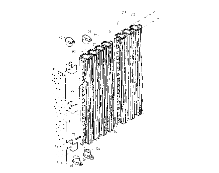
FIG. 1 is a partial exploded view of a wall system
05 in accordance with the present invention;
FIG. 2 is a plane view of the wall member;
FIG. 3 is a cross sectional view of the wall
member;
FIG. 4 is a cross sectional view of the wall
system;
FIG. 5 is an enlarged schematic view illustrating
portion of the wall system;
FIG. 6 is a cross sectional view taken along lines
6-6 of FIG. 4;
FIGS. 7, 8 and 9 are schematic views illustrating
three applications of the wall system;
FIG. 10 is a front view iLlustrating another
application of the wall system; and
FIG. 11 is an enlarged view illustrating portion
of the wall system as shown in FIG. 1~.
DETAIEED DESCRIPTION OF THE PREFERRED EMBODIMENT
Referring to the drawings, and initially to FIGS.
1 to 6, a wall system in accordance with the present
invention comprises a number of retaining members 11
fixed, by screws 12, to supporting means 1, such as
column, ceiling or floor, best shown in FIG. 6, in
order to engage with wall members 2, such that the wall

214150~
members can be stably retained in place by the
retaining members 11, the wall members 2 can be made
with plastic materials, metal or steel materials or
other construction materials, and can be made to
05 different sizes, each of the wall members 2 includes a
number of beams 21 each having a hollow interior formed
therein and each having two open ends enclosed by plugs
22, the plugs 22 may be formed with an aperture 220 for
threading electric wires or tubes, the beams 21 form
the primary construction of the wall system and are
secured together by intermediate ribs 211 each having a
number of openings 23 formed therein, each of the wall
members 2 includes two side ribs 212 each having a
number of orifices 24 formed therein, as shown in FIGS.
4 and 5, the wall members 2 can be secured together by
wires 25 which are threaded through the orifices 24
formed in the side ribs of the wall members 2. A numher
of reinforcing ribs are formed on the outer peripheral
portions of the beams 21.
As shown in FIG. 4, the wall system includes one
or more wall members 2 secured together, and an outer
layer 10 of concrete material having a thickness close
to 1.5 cm, the concrete material is sprayed or injected
onto the wall members 2 with a rate close to 20 l/min,
or 1200 l/hr, such that 80 m2 of the outer layer 10 can
be formed within one hour, the concrete material can be
dried within 60 minutes, and can be cured within 120

2141509
._
minutes. The concrete material on both sides of the
wall members 2 are solidly secured together via the
openings 23 and the orifices 24. In order to increase
sound shielding effect and the heat resistive effect,
OS foamable materials or other heat resistive material may
be injected into the hollow interior of the beams 21.
Referring next to FIG. 7, a number of brackets 26
can be hung on the wall members 2 with the openings 23
of the wall members 2, and a number of steel rods 27
can be retained in place by the brackets 26 so as to
reinforce the wall system.
Referring next to FIG. 8, instead of the steel
rods 27 as shown in FIG. 7, a net member 3 can be
secured to the wall member 2 by the brackets 26 which
lS include tips for supporting the net member 3.
Referring next to FIG. 9, i 1 lustrated is an
application of the tubes and electric wires can be
installed within the beams.
Referring next to FIG. 10, a number of pipes 28
can be provided to communicate the hollow interiors of
the beams 21 together, such that, if required, warm air
may be injected into the wall members 2 ~nd ma~ flow
through the beams 21 via the pipes 28, so as to warm
the wall system during winter.
Accordingly, the wall system in accordance with
the present invention includes a greatly simplified
configuration which can be easily constructed.

2~415()~
Although this invention has been described with a
certain degree of particularity, it is to be understood
that the present disclosure has been made by way of
example only and that numerous changes in the detailed
05 construction and the combination and arrangement of
parts may be resorted to without departing from the
spirit and scope of the invention as hereinafter
claimed.

Representative Drawing
A single figure which represents the drawing illustrating the invention.
Administrative Status

2024-08-01:As part of the Next Generation Patents (NGP) transition, the Canadian Patents Database (CPD) now contains a more detailed Event History, which replicates the Event Log of our new back-office solution.

Please note that "Inactive:" events refers to events no longer in use in our new back-office solution.

For a clearer understanding of the status of the application/patent presented on this page, the site Disclaimer , as well as the definitions for Patent , Event History , Maintenance Fee  and Payment History  should be consulted.

Event History

Description Date
Time Limit for Reversal Expired 2007-01-31
Inactive: IPC from MCD 2006-03-11
Letter Sent 2006-01-31
Grant by Issuance 1999-04-06
Pre-grant 1998-11-05
Inactive: Final fee received 1998-11-05
Letter Sent 1998-08-14
Notice of Allowance is Issued 1998-08-14
Inactive: Status info is complete as of Log entry date 1998-08-12
Inactive: Application prosecuted on TS as of Log entry date 1998-08-12
Inactive: Approved for allowance (AFA) 1998-05-08
Application Published (Open to Public Inspection) 1995-09-04
All Requirements for Examination Determined Compliant 1995-05-09
Request for Examination Requirements Determined Compliant 1995-05-09

Abandonment History

There is no abandonment history.

Maintenance Fee

The last payment was received on 1998-12-30

Note : If the full payment has not been received on or before the date indicated, a further fee may be required which may be one of the following

  • the reinstatement fee;
  • the late payment fee; or
  • additional fee to reverse deemed expiry.

Please refer to the CIPO Patent Fees web page to see all current fee amounts.

Fee History

Fee Type Anniversary Year Due Date Paid Date
MF (application, 3rd anniv.) - small 03 1998-02-02 1998-01-30
Final fee - small 1998-11-05
MF (application, 4th anniv.) - small 04 1999-02-01 1998-12-30
MF (patent, 5th anniv.) - small 2000-01-31 2000-01-12
MF (patent, 6th anniv.) - small 2001-01-31 2001-01-22
MF (patent, 7th anniv.) - small 2002-01-31 2002-01-16
MF (patent, 8th anniv.) - small 2003-01-31 2003-01-14
MF (patent, 9th anniv.) - small 2004-02-02 2003-12-31
MF (patent, 10th anniv.) - small 2005-01-31 2005-01-05
Owners on Record

Note: Records showing the ownership history in alphabetical order.

Current Owners on Record
CHING-LIANG KUO
Past Owners on Record
None
Past Owners that do not appear in the "Owners on Record" listing will appear in other documentation within the application.
Documents

To view selected files, please enter reCAPTCHA code :


To view images, click a link in the Document Description column. To download the documents, select one or more checkboxes in the first column and then click the "Download Selected in PDF format (Zip Archive)" or the "Download Selected as Single PDF" button.

List of published and non-published patent-specific documents on the CPD .

If you have any difficulty accessing content, you can call the Client Service Centre at 1-866-997-1936 or send them an e-mail at CIPO Client Service Centre.


Document
Description 
Date
(yyyy-mm-dd) 
Number of pages   Size of Image (KB) 
Representative drawing 1999-04-01 1 28
Cover Page 1995-10-23 1 14
Drawings 1995-09-04 8 362
Description 1995-09-04 6 175
Abstract 1995-09-04 1 16
Claims 1995-09-04 2 44
Representative drawing 1998-03-13 1 59
Description 1998-04-22 7 207
Claims 1998-04-22 2 63
Cover Page 1999-04-01 1 62
Commissioner's Notice - Application Found Allowable 1998-08-14 1 166
Maintenance Fee Notice 2006-03-28 1 172
Fees 2003-01-14 1 30
Fees 2002-01-16 1 29
Correspondence 1998-11-05 1 31
Fees 2003-12-31 1 28
Fees 1998-01-30 1 44
Fees 1998-12-30 1 32
Fees 2000-01-12 1 30
Fees 2001-01-22 1 31
Fees 2005-01-05 1 27
Fees 1996-12-27 1 37
Prosecution correspondence 1995-05-09 2 102
Prosecution correspondence 1998-02-20 3 64
Examiner Requisition 1997-09-23 2 47
Prosecution correspondence 1998-02-20 1 46
Courtesy - Office Letter 1995-08-07 1 28
Prosecution correspondence 1995-01-31 5 187