Sélection de la langue

Search

Sommaire du brevet 2141509 

Énoncé de désistement de responsabilité concernant l'information provenant de tiers

Une partie des informations de ce site Web a été fournie par des sources externes. Le gouvernement du Canada n'assume aucune responsabilité concernant la précision, l'actualité ou la fiabilité des informations fournies par les sources externes. Les utilisateurs qui désirent employer cette information devraient consulter directement la source des informations. Le contenu fourni par les sources externes n'est pas assujetti aux exigences sur les langues officielles, la protection des renseignements personnels et l'accessibilité.

Disponibilité de l'Abrégé et des Revendications

L'apparition de différences dans le texte et l'image des Revendications et de l'Abrégé dépend du moment auquel le document est publié. Les textes des Revendications et de l'Abrégé sont affichés :

  • lorsque la demande peut être examinée par le public;
  • lorsque le brevet est émis (délivrance).
(12) Brevet: (11) CA 2141509
(54) Titre français: SYSTEME DE CONSTRUCTION D'UN MUR
(54) Titre anglais: WALL SYSTEM
Statut: Périmé et au-delà du délai pour l’annulation
Données bibliographiques
(51) Classification internationale des brevets (CIB):
  • E04B 2/62 (2006.01)
  • E04B 1/00 (2006.01)
  • E04B 2/84 (2006.01)
(72) Inventeurs :
  • KUO, CHING-LIANG (Taïwan, Province de Chine)
(73) Titulaires :
  • CHING-LIANG KUO
(71) Demandeurs :
  • CHING-LIANG KUO (Taïwan, Province de Chine)
(74) Agent: ROBIC AGENCE PI S.E.C./ROBIC IP AGENCY LP
(74) Co-agent:
(45) Délivré: 1999-04-06
(22) Date de dépôt: 1995-01-31
(41) Mise à la disponibilité du public: 1995-09-04
Requête d'examen: 1995-05-09
Licence disponible: S.O.
Cédé au domaine public: S.O.
(25) Langue des documents déposés: Anglais

Traité de coopération en matière de brevets (PCT): Non

(30) Données de priorité de la demande:
Numéro de la demande Pays / territoire Date
08/205,247 (Etats-Unis d'Amérique) 1994-03-03

Abrégés

Abrégé français

Système mural comprenant un ou plusieurs éléments de mur, ainsi que plusieurs dispositifs de retenue fixés à des colonnes ou à des poteaux et engagés avec les éléments de mur afin de retenir ces derniers en place. Les éléments de mur sont constitués de plusieurs poutres présentant chacune un intérieur creux, ainsi que de plusieurs nervures intermédiaires formées entre les poutres afin de joindre solidement ensemble ces dernières. Une couche extérieure peut être formée sur la partie périphérique extérieure des éléments de mur et s'engager avec les ouvertures des nervures intermédiaires afin d'obtenir une apparence extérieure lisse.


Abrégé anglais


A wall system includes one or more wall members,
and a number of retaining devices fixed to columns or
posts and engaged with the wall members for retaining
the wall member in place. The wall member includes a
number of beams each having a hollow interior, and a
number of intermediate ribs formed between the beams so
as to solidly couple the beams together. An outer layer
of can be formed on the outer peripheral portion of the
wall member and engaged with the openings of the
intermediate ribs so as to form a smooth outer
appearance.

Revendications

Note : Les revendications sont présentées dans la langue officielle dans laquelle elles ont été soumises.


WHAT IS CLAIMED IS:
1. A wall system for connection to a supporting
means, said wall system comprising at least one wall member
having a plurality of integrally formed beams each having a
hollow interior formed therein, and retaining means for
securely engaging said supporting means so as to retain said at
least one wall member in place, wherein said at least one wall
member includes two side ribs, each having a plurality of
orifices formed therein and extending completely through said
side ribs from one surface of the side ribs to an opposite
surface of the side ribs, said at least one wall member further
comprising a plurality of external reinforcing ribs extending
outwardly from an outside surface of each of said integrally
formed beams, said wall system further comprising an outer
layer secured to said wall member and engaged with said
orifices of said side ribs, wherein said outer layer comprises
a solidifiable material which extends through said orifices,
and becomes secured, after solidification, to said at least one
wall member through said orifices.
2. The wall system according to claim 1, wherein
said at least one wall member comprising a plurality of beams
each having a hollow interior formed therein further comprises
a plurality of intermediate ribs formed between said beams so
as to solidly couple said beams together.
3. The wall system according to claim 2, wherein
each of said intermediate ribs includes a plurality of openings
formed therein, and wherein said outer layer is also engaged
with said plurality of openings.
4. A wall system according to claim 3, wherein said
wall member includes a plurality of brackets engaged with said
openings for supporting rods.

5. A wall system according to claim 2, wherein each
of said beams includes two open ends, and a plug engaged with
each of said open ends of said beams so as to enclose said
beams.
6. A wall system according to claim 5, wherein said
plug includes an aperture formed therein for inserting tubes or
electric wires.
7. A wall system according to claim 2, wherein said
wall member includes a plurality of tubes connected between
said beams so as to communicate said hollow interiors of said
beams with one another.

Description

Note : Les descriptions sont présentées dans la langue officielle dans laquelle elles ont été soumises.

'~ 2~4~09
TITLE: WALL SYSTEM
BACKGROUND OF THE INVENTION
1. Field of the Invention
The present invention relates to a wall system,
05 and more particularly to a wall system having a novel
configuration.
2. Description of the Prior Art
Typically, wall systems are formed by bricks, or
formed by molding processes, i.e., building, with wood
boards, a mold cavity having a shape corresponding to
that of the wall systems, and pouring concrete into the
mold cavity in order to form the wall system, the wall
systems are suitable for building houses only.
Recently, huge buildings are built with steel
construction, mold boards are then fixed around the
steel construction, and concrete is then engaged in the
mold cavitv formed by the mold boards, it is a]so
complicated to build the mold boards.
The present invention has arisen to mitigate
and/or obviate the afore-described disadvantages of the
conventional wall systems.
SUMMARY OF THE INVENTION
The primary objective of the present invention is
to provide a wall system which can be easily
~ 25 constructed.
In accordance with one aspect of the invention,
there is provided a wall system for being constructed

Q ~
'_
in supporting means comprising at least one wall member
including two side portions, and ret~;n;ng means secured to the
supporting means for retaining the wall member in place.
The wall member includes a plurality of beams each
having a hollow interior formed therein, and a plurality of
intermediate ribs formed between the beams so as to solidly
couple the beams together. Each of the intermediate ribs
includes a plurality of openings formed therein, the wall
system further comprises an outer layer secured to the wall
member and engaged with the openings of the intermediate ribs.
The wall member includes a plurality of brackets engaged with
the openings for supporting rods.
Each of the beams includes two open ends, and a plug
engaged with each of the open ends of the beams so as to
enclose the meams, the plug includes an aperture formed therein
for inserting tubes or electric wires.
The wall member includes two side ribs each having a
plurality of orifices formed therein, the wall system further
comprises an outer layer secured to the wall member and engaged
with the orifices of the side ribs.
The wall member includes a plurality of tubes
connected between the beams so as to communicate the hollow
interior of the beams with one another.
A further object of the present invention is to
provide a wall system for connection to a supporting means,
said wall system comprising at least one wall member having a
plurality of integrally formed beams each havinga hollow
interior formed therein, and retaining means for securely
engaging said supporting means so as to retain said at least
one wall member in place, wherein said at least one wall member
includes two side ribs, each having a plurality of orifices
formed therein and extending completely through said side ribs
from one surface of the side ribs to an opposite surface of the
side ribs, said at least one wall member further comprising a
plurality of external reinforcing ribs extending outwardly from
an outside surface of each of said integrally formed beams,

s ~ ~
-
said wall system further comprising an outer layer secured to
said wall member and engaged with said orifices of said side
ribs, wherein said outer layer comprises a solidifiable
material which extends through said orifices, and becomes
secured, after solidification, to said at least one wall member
through said orifices.
Further objectives and advantages of the present
invention will become apparent from a careful reading
y,

214~ 509
of a detailed description provided hereinbelow, with
appropriate reference to accompanying drawings.
BRIEF DESCRIPTION OF THE DRAWINGS
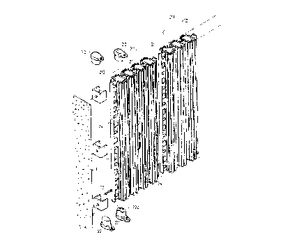
FIG. 1 is a partial exploded view of a wall system
05 in accordance with the present invention;
FIG. 2 is a plane view of the wall member;
FIG. 3 is a cross sectional view of the wall
member;
FIG. 4 is a cross sectional view of the wall
system;
FIG. 5 is an enlarged schematic view illustrating
portion of the wall system;
FIG. 6 is a cross sectional view taken along lines
6-6 of FIG. 4;
FIGS. 7, 8 and 9 are schematic views illustrating
three applications of the wall system;
FIG. 10 is a front view iLlustrating another
application of the wall system; and
FIG. 11 is an enlarged view illustrating portion
of the wall system as shown in FIG. 1~.
DETAIEED DESCRIPTION OF THE PREFERRED EMBODIMENT
Referring to the drawings, and initially to FIGS.
1 to 6, a wall system in accordance with the present
invention comprises a number of retaining members 11
fixed, by screws 12, to supporting means 1, such as
column, ceiling or floor, best shown in FIG. 6, in
order to engage with wall members 2, such that the wall

214150~
members can be stably retained in place by the
retaining members 11, the wall members 2 can be made
with plastic materials, metal or steel materials or
other construction materials, and can be made to
05 different sizes, each of the wall members 2 includes a
number of beams 21 each having a hollow interior formed
therein and each having two open ends enclosed by plugs
22, the plugs 22 may be formed with an aperture 220 for
threading electric wires or tubes, the beams 21 form
the primary construction of the wall system and are
secured together by intermediate ribs 211 each having a
number of openings 23 formed therein, each of the wall
members 2 includes two side ribs 212 each having a
number of orifices 24 formed therein, as shown in FIGS.
4 and 5, the wall members 2 can be secured together by
wires 25 which are threaded through the orifices 24
formed in the side ribs of the wall members 2. A numher
of reinforcing ribs are formed on the outer peripheral
portions of the beams 21.
As shown in FIG. 4, the wall system includes one
or more wall members 2 secured together, and an outer
layer 10 of concrete material having a thickness close
to 1.5 cm, the concrete material is sprayed or injected
onto the wall members 2 with a rate close to 20 l/min,
or 1200 l/hr, such that 80 m2 of the outer layer 10 can
be formed within one hour, the concrete material can be
dried within 60 minutes, and can be cured within 120

2141509
._
minutes. The concrete material on both sides of the
wall members 2 are solidly secured together via the
openings 23 and the orifices 24. In order to increase
sound shielding effect and the heat resistive effect,
OS foamable materials or other heat resistive material may
be injected into the hollow interior of the beams 21.
Referring next to FIG. 7, a number of brackets 26
can be hung on the wall members 2 with the openings 23
of the wall members 2, and a number of steel rods 27
can be retained in place by the brackets 26 so as to
reinforce the wall system.
Referring next to FIG. 8, instead of the steel
rods 27 as shown in FIG. 7, a net member 3 can be
secured to the wall member 2 by the brackets 26 which
lS include tips for supporting the net member 3.
Referring next to FIG. 9, i 1 lustrated is an
application of the tubes and electric wires can be
installed within the beams.
Referring next to FIG. 10, a number of pipes 28
can be provided to communicate the hollow interiors of
the beams 21 together, such that, if required, warm air
may be injected into the wall members 2 ~nd ma~ flow
through the beams 21 via the pipes 28, so as to warm
the wall system during winter.
Accordingly, the wall system in accordance with
the present invention includes a greatly simplified
configuration which can be easily constructed.

2~415()~
Although this invention has been described with a
certain degree of particularity, it is to be understood
that the present disclosure has been made by way of
example only and that numerous changes in the detailed
05 construction and the combination and arrangement of
parts may be resorted to without departing from the
spirit and scope of the invention as hereinafter
claimed.

Dessin représentatif
Une figure unique qui représente un dessin illustrant l'invention.
États administratifs

2024-08-01 : Dans le cadre de la transition vers les Brevets de nouvelle génération (BNG), la base de données sur les brevets canadiens (BDBC) contient désormais un Historique d'événement plus détaillé, qui reproduit le Journal des événements de notre nouvelle solution interne.

Veuillez noter que les événements débutant par « Inactive : » se réfèrent à des événements qui ne sont plus utilisés dans notre nouvelle solution interne.

Pour une meilleure compréhension de l'état de la demande ou brevet qui figure sur cette page, la rubrique Mise en garde , et les descriptions de Brevet , Historique d'événement , Taxes périodiques et Historique des paiements devraient être consultées.

Historique d'événement

Description Date
Le délai pour l'annulation est expiré 2007-01-31
Inactive : CIB de MCD 2006-03-11
Lettre envoyée 2006-01-31
Accordé par délivrance 1999-04-06
Préoctroi 1998-11-05
Inactive : Taxe finale reçue 1998-11-05
Lettre envoyée 1998-08-14
Un avis d'acceptation est envoyé 1998-08-14
Inactive : Renseign. sur l'état - Complets dès date d'ent. journ. 1998-08-12
Inactive : Dem. traitée sur TS dès date d'ent. journal 1998-08-12
Inactive : Approuvée aux fins d'acceptation (AFA) 1998-05-08
Demande publiée (accessible au public) 1995-09-04
Toutes les exigences pour l'examen - jugée conforme 1995-05-09
Exigences pour une requête d'examen - jugée conforme 1995-05-09

Historique d'abandonnement

Il n'y a pas d'historique d'abandonnement

Taxes périodiques

Le dernier paiement a été reçu le 1998-12-30

Avis : Si le paiement en totalité n'a pas été reçu au plus tard à la date indiquée, une taxe supplémentaire peut être imposée, soit une des taxes suivantes :

  • taxe de rétablissement ;
  • taxe pour paiement en souffrance ; ou
  • taxe additionnelle pour le renversement d'une péremption réputée.

Veuillez vous référer à la page web des taxes sur les brevets de l'OPIC pour voir tous les montants actuels des taxes.

Historique des taxes

Type de taxes Anniversaire Échéance Date payée
TM (demande, 3e anniv.) - petite 03 1998-02-02 1998-01-30
Taxe finale - petite 1998-11-05
TM (demande, 4e anniv.) - petite 04 1999-02-01 1998-12-30
TM (brevet, 5e anniv.) - petite 2000-01-31 2000-01-12
TM (brevet, 6e anniv.) - petite 2001-01-31 2001-01-22
TM (brevet, 7e anniv.) - petite 2002-01-31 2002-01-16
TM (brevet, 8e anniv.) - petite 2003-01-31 2003-01-14
TM (brevet, 9e anniv.) - petite 2004-02-02 2003-12-31
TM (brevet, 10e anniv.) - petite 2005-01-31 2005-01-05
Titulaires au dossier

Les titulaires actuels et antérieures au dossier sont affichés en ordre alphabétique.

Titulaires actuels au dossier
CHING-LIANG KUO
Titulaires antérieures au dossier
S.O.
Les propriétaires antérieurs qui ne figurent pas dans la liste des « Propriétaires au dossier » apparaîtront dans d'autres documents au dossier.
Documents

Pour visionner les fichiers sélectionnés, entrer le code reCAPTCHA :


Pour visualiser une image, cliquer sur un lien dans la colonne description du document. Pour télécharger l'image (les images), cliquer l'une ou plusieurs cases à cocher dans la première colonne et ensuite cliquer sur le bouton "Télécharger sélection en format PDF (archive Zip)" ou le bouton "Télécharger sélection (en un fichier PDF fusionné)".

Liste des documents de brevet publiés et non publiés sur la BDBC .

Si vous avez des difficultés à accéder au contenu, veuillez communiquer avec le Centre de services à la clientèle au 1-866-997-1936, ou envoyer un courriel au Centre de service à la clientèle de l'OPIC.


Description du
Document 
Date
(aaaa-mm-jj) 
Nombre de pages   Taille de l'image (Ko) 
Dessin représentatif 1999-04-01 1 28
Page couverture 1995-10-23 1 14
Dessins 1995-09-04 8 362
Description 1995-09-04 6 175
Abrégé 1995-09-04 1 16
Revendications 1995-09-04 2 44
Dessin représentatif 1998-03-13 1 59
Description 1998-04-22 7 207
Revendications 1998-04-22 2 63
Page couverture 1999-04-01 1 62
Avis du commissaire - Demande jugée acceptable 1998-08-14 1 166
Avis concernant la taxe de maintien 2006-03-28 1 172
Taxes 2003-01-14 1 30
Taxes 2002-01-16 1 29
Correspondance 1998-11-05 1 31
Taxes 2003-12-31 1 28
Taxes 1998-01-30 1 44
Taxes 1998-12-30 1 32
Taxes 2000-01-12 1 30
Taxes 2001-01-22 1 31
Taxes 2005-01-05 1 27
Taxes 1996-12-27 1 37
Correspondance de la poursuite 1995-05-09 2 102
Correspondance de la poursuite 1998-02-20 3 64
Demande de l'examinateur 1997-09-23 2 47
Correspondance de la poursuite 1998-02-20 1 46
Courtoisie - Lettre du bureau 1995-08-07 1 28
Correspondance de la poursuite 1995-01-31 5 187