Note: Descriptions are shown in the official language in which they were submitted.
.i:
,,: `: 1
~ 2:L~181~
. .
;i~
SPECIFICATION `
COLLECTION AND PROCESSING APPARATUS C)F REPEATEDLY
USD RECORDING MEDIA
'~ ~ S ;". '.,"."'
~; TECHNICAL FIELD i -
This invention relates to a collection and processing
apparatus of recording media on which necessary items are
~; 10 erasably recorded for transferring information, and in particular
j ~ ~ to a recording medium collection and processing apparatus which -
separates recording media according to whether or not they can
be~ used~ and processes only usable recording media so ~as to
recycle them. :
TECHNICAL BACKGROUND --
~ ; In a gaming house containing gaming machines such as
=~ pinball machines, a player plays games at a gaming machine and,',`!, ','',
20 obtains game play media by winning games. The number of game
play media won by the piayer is counted using a game play media
` ' counter, for example. The game play media counter records the
count result on paper, such as thermosensible paper, using a
recording head, and issues a receipt. For recording, digits and a
- ~ ~ ~ 25 bar code indicating the number of game play media are printed on
~ paper, for example.
`~
:- 2 2141815 :
In such a gaming house, the player receives the receipt and
can exchange the receipt for a prize equivalent to the number of
game play media indicated on the receipt at an adjustment
counter or window. The player may exchange the receipt for cash
5 if such a transaction is legal.
Incidentally, the applicant proposed use of repeatedly
usable recording media of card type in place of such receipts to
avoid wasting of resources in Japanese Patent Application No. Hei
3-272659 (Japanese Patent Laid-Open No. Hei 5-111570, laid
1~ open to public on May 7, 1993) and Japanese Patent Application
No.~Hei 3-260879 (Japanese Patent Laid-Open No. Hei 5-96058,
laid open to public on April 20, 1993). Since the recording media
` ~ ~ can be recycled, ~ excellent effects of contributing to cost
reduction, resource conservation, etc., can be expe~ted. However,
l S the number of times such a recording medium can be repeatedly
used is finite; to~secure reliability in recording data, the
recording media need to be discarded within certain limits.
To use a large number of such recording media, for example,
in~a gaming~ house, the recording media may be replaced with new
20 ones all together. However, this method requires collection of a
large number of recording media and teplacement of thern all with
new ones, which is labor consuming, and is not an easy method.
Simultaneous replacement of recording media having different
:: :
usage conditions introduces the following problem: When tha
2 5 recording media are considered individually, replacement of those
'~` I~ ;
,
.
3 21~18~
-~
frequently used is delayed; whereas replacement of those less
, , . .- ,
frequently used is wasteful.
If such a problem can be solved, such recording media can be ~ ~-
used not only in gaming houses, but also as tickets for parking
lots and facilities, railway tickets, etc. ~ i-
DISCLOSUREOFINVENTION ~
. . ~;:-
It is therefore an object of the invention to provide a
10 recording medium collection and processing apparatus which canindividually manage the number of recycle times of each
recording medium on which the record contents can be erased for
. . .
repeated usa, and can determine whether or not the recording ; -
~ ..
medium is to be discarded based on the number of recycle tirnes --
15 for automatically discarding recording media without delay or
~- ~ waste.
To this end, according to the invention, there is provided a
recording medium collection and processing apparatus for
~i recycling recording media which are capable of erasably recording
data and are repeatedly usable, the apparatus comprising:
a main transport passage for transporting a recording
medium taken in from the outside; ; .,
~i a record data reader for reading at least data indicating the
number of recycle times of the recording medium taken in from
2~ the outside, written in a specific area of the recording medium;
~,~" ",, , , ~ "
~ .;, .-, , . . - , . .. . .. .... .. . . .
4 214181~
: ,~
a controller for determining whether or not the recording
medium is to be reused based on the read data indicating the
number of recycle times, if the recording medium is not reused,
the controller outputting a discarding command, and if it is
S reused,-updating the number of recycle times and outputting data
;~ indicating the updated number of recycle times and a number-of-
; ~ times write commancl;
a separation section for separating the recording medium
for which the discarding command is issued from the main
1~ 10 transport passage; and
. a number-of-times writer for writing data indicating the
number of recycle times of the recording medium into a specific
area of the recording medium upon receipt of the number-of-
recycle-times write command.
T he collection and processing apparatus of the invention can -
further include an eraser for erasing record data written onto the
recording medium to be reused.
The ooilection and processing apparatus of the invention can
g further~ include a display for displaying the contents of record
data read by the record data reader.
The collection and processing apparatus of the invention can
~.:
further include a first stacker for storing recycled recording ;
media and a second stacker for storing recording media to be
discarded.
; : "
~ .
5 21~181~ ~
The controller used in the invention comprises means for
counting the number of recycled recording media and means for --
:: .
counting the number of recording media to be discarded.
The collection and processing apparatus of the invention can --
5 further include a display for displaying the number of recycled
re`cording media counted by the counting means and a display for ~.
displaying the number of recording media to be discarded, counted -
by the counting means.
The controller can check whether or not the number of
~- 10 recycled recording media reaches a capacity of the first stacker ~;.
and: whether or not the number of recording media to be discarded
reaches a capacity of the second stacker, and if either of the
~; numbers reaches the capacity of the corresponding stacker, the ~;
controller can cause the display for displaying the contents of
record data to display a prestored message requesting the -~ ;
reoording media to be taken out from the stacker.
For example, a card having material to allow a physical ~ -~
change to be made locally and reversibly as a recording layer can ~-
be~ used as a recordlng~medium. For example, a medium can be
used which comprises an organic substance having an optical -
characteristic of transmittance, etc., changing reversibly with a
- temperature disposed as a recording layer.
In the invention, the number of times the recording medium -~
;. ~ , .
has been recycled is recorded in a specific area of the reused -
``~; 25 recording medium, whereby when the game play media are
~ collected, first the number of recycle times recorded on the
c; ~
~ ~:',`,,'
`;: ~'
6 2~18~5
:~
recording medium can be read for determining whether or not it
reaches a predetermined number of times. Therefore, a large
number of recording media different in use frequency can be
managed individually. As a result, the discard time (life) of each
5 recording medium can be known individually, eliminating wasteful -
processing. Each time a recording medium is collectedl the
number of ~times the recording medium has been recycled is
checked, thus it can be discarded without delay.
1 0 BRIEF DESCRIPTION OF THE DRAWINGS
1"
In the accompanying drawings:
I,
Figure 1 is a block diagram showing the entire configuration
of a recycle card system to which a recording medium collection
~ 15 ~ and processing apparatus of one embodiment of the invention is
:` ~ applied;
,
Figure 2 is a perspective view showing the appearance of
the recording medium collection and processing apparatus of the
~ embodiment of the invention;
:; 20 Figure 3 is a sectional view schematically showing the `~~:, internal structure of the recording medium collection and
processing apparatus of the embodiment of the invention;
~ Figure 4 is a block diagram showing the function of a card
``~ separation and recycling unit, a component of the recording
25` medium collection and processing appanatus of the embodiment of
the invention;
...... ... ,-.. .. . . . . ... .
'' ,:~
, '~
'~' ', ~' ,'''
7 2 1 4 ~
Figure 5 is a flowchart showing an operation procedure of a
controller built into the card separation and recycling unit; 1 -
Figure 6A is a plan view showing the structure of a card, a ~ .
recording medium to be processed by the collection and - .
5 processing apparatus of the invention; . :~
Figure 6B is a plan view showing a state before items are : :-
recorded on the card shown in Figure 6A;
Figure 7 is a sectional view taken on line ll-ll of Figure 6B;
Figure 8 is a schematic illustration showing example
~- , -
10 structures of a dispensing stacker and an issuing machine used to
issue recording media to be processed by the apparatus of the
invention; and
Figure 9 is a schematic illustration showing the structure -~
-` ~ of a separation section, a constituent member of the invention.
: ~ BEST MODE FOR CARRYING OUT THE INVENTION
; Referring now to the accompanying drawings, there is
shown one embodiment of the invention.
20 ~ ~ Figure 1 shows the entire configuration of a recycle card
system using a card 3 as a recording medium to which a `-
~; collection and processing apparatus 10 of the embodiment is ~ ~`
~: ~ applied. The recycle card system is a system for enabling cards ~ ~ `
to be repeatedly used to record the count result of a counter 1 of 11
25 game play media, such as pinball~s, in a gaming house.
.~
~ ~,.,:,
~ ' .,`:
~,,,., - . , .. . ~ ~
-
8 214181~
Placed on the card issuing side are a counter 1 for counting
the number of garne play media, a dispensing stacker 4 for
stacking cards for dispensing, and an issuing machine 2 for taking
out a card from the stacker 4, reading the count result from the
S counter 1, and recording the count result on the card. The
embodiment assumes that these components are integrated in one
piece and housed in a common cabinet. Of course, they can be
provided as separate units. They may be contained in a game play
media lending machine or a gaming machine.
The collection and processing apparatus 10 for collecting
and processing cards is placed on the card collection side. The
collection and processing apparatus 10 comprises a card
separation and recycling unit 11, a discarded card stacker 12 for
storing discarded cards, and a recycled card stacker 13 for
storing reusable cards. In the embodiment, these components are
collected as an unit. The card separation and recycling unit 11
takes in cards and separates the cards according to whether or
not they can be used, then recycles reusable cards. Also, it reads
data recorded on the card and performs necessary processing; for
example, it reads information indicating the number of game play
~- i media recorded on the card and displays it.
Figures 6A and 6B are external views of one example of a
recording medium used in the embodiment. Figure 7 shows the
sectional structure of the recording medium. ~-
As- shown in Figure 7, the card 3 comprises a recording layer
302 on which necessary items can be visually recorded and erased
.. .. ..
9 21~ 5 ~ ~:
'I ,' .' ' ` ' .
by applying heat so that the card can be used repeatedly, on a `~
substrate 301. The recording layer 3 consists essentially of an .; ~.
organic compound whose crystal aggregates to a visible state
¦ upon application of heat at a first specific temperature and
S diffuses to an invisible state upon application of heat at a second
specific temperature different from the first specific
temperature. An organic compound as a specific example
comprises a higher fatty acid such as a behenic acid, a lauric
,~ acid, or a stearic acid dispersed in a polymeric matrix material
~- 10 such as vinylidene chloride to which a small amount of a surface
active agent, etc., is added The recording layer 3 can also
comprise ultrafine particles of organic molecules of a stearic ~.
acid, etc" dispersed in a vinyl chloride resin having high heat
resistance, for example. The first specific temperature is a -~
: ~ .
15 temperature of 100C or higher, for example; the second specific
temperature is a temperature 10C or more higher than the first `
specific temperature, for example
The surface of the recording layer 302 may be furthermore
~` coated with a protective film.
,. . ..
The recording layer 302 can be made of a substance which is ~ -
' invisible at room temperature and when locally heated, the heated
; part is polycrystallized, causing light to be irregularly reflected,
thus making it visible. By applying heat in a specific pattern to
~ ~ such a recording layer 302, the recording layer 302 can be locally
; 25 polycrystallized according to the pattern for representing
; ~ characters, digits, etc. On the other hand, if heat is applied at a ;~
. . ':;'
':
2~41~
different temperature from the predetermined temperature, for
example, at a temperature about 10C higher than the temperature
at crystallization, the crystal can diffuse, causing the
characters, digits, etc., to disappear.
The card 3 has portions for indicating entries which need
not be erased, in addition to the recording layer 302 on which
erasable indication can be made. For example, printed on one side
oS the card 3 in normal ink which is difficult to erase ar~ an
indication 311 for showing thanks to customers, such as "THANK
YOU," indication 312 of the gaming house name where the card can
be used, indication 314 of expiration date, indication 3~5
"REMAlNDE~j" and indication 317 "GAME PLAY MED!UM COUNT."
Indication 321 of the remaining amount of money, obtained
by subtracting the amount of money paid to buy game play media
from the amount of money input to a game play media lending ~;
machine (in~ this case, 8000 yen), is written within a frame 316
by~ applying heat at a predetermined temperature for recording.
Likewise, indication 322 of the number of game play media (in
this case, 2580) is written within a frame 318 by applying heat
at the predetermined temperaturs for recording. Date indication
313 is made above the REMAINDER indication. A bar code
indication portion 323 is on the right of the REMAINDER and GAME
` PLAY MEDIA COUNT areas. In the bar code indication portion 323,
number-of-recycle-times indication 323a, remainder indication
:~ 25 323b, and game play media count indication 323c are recorded in
bar codes.
. .
~ 1 1 21~181~ ~ -
~ - . . . .
The dispensing stacker 4 and the issuing machine 2 have
structures as shown in Figure 8, for example.
The dispensing stacker 4 comprises a case 431, a
transporter 432, and a recording section 433. The case 431
5 consists of surrounding walls 431d to accommodate a plurality of
cards 3 one over the other therewithin; they are used as a card
holder.
One end of a lever 431a is pivotally secured to the top end ~ --
of the case 431, and a weight 431c is secured via a short lever
10 431b to the other end of the lever 431a. The dispensing stacker 4
is adapted to supply cards 3 to the side of a transport plane 441a
by pressure of the weight 431c. ~ ~-
~ ~ ~ The transporter 432 is adapted to take out cards 3 one at a .;~ time from the case 431 and feed them along a transport passage
432a. The transporter 432 comprises a transport belt mechanism
441, a transport guide 442, and transport rollers 443.
The transport belt mechanism 441 is disposed below the
surrounding walls 431d so that a gap to allow cards 3 to be
discharged one at a time can be formed between the transport ~` -
belt mechanism 441 and the surrounding walls 431d of the case ~','.,.,'!,'.'
431 to place the card 3 within the surrounding walls 431d on the
transport plane 441a. More particularly, the transport belt
mechanism 441 has an endless belt 441d placed on a driving ~ -
pulley 441b and a driven pulley 441c for moving the card 3 on the
transport plane 441a in the gap direction by power. The endless ~'' ~!,',
:
1 2 2~4181~
belt 441d has two engagement parts 441e, 441e for enyagement
with one card 3 placed on the transport plane 441a.
The issuing machine 2 has a recording section 233, a
transport roller 243, and a transport guide 242.
S The transport guide 242 has a transport passage 232a for
guidin~ a card 3 discharged from the transport belt mechanism
.
441 and a card outlet 242a, a card discharge section, disposed at
the end of the transport passage 232a.
The transport rollers 243 comprise a pinch roller 243a and
1 0 a card drive roller 243b, between which the transport passage
~; 232a is sandwiched downstream of the recording section 233.
.
- The transport rollers 243 are adapted to be driven by power for
transporting cards 3 from the gap through the transport passage
232a~ of the~ transport guide 242 to the card outlet 242a.
h ~ 15 ~ The~recording section 233 is disposed along the transport
;passage 232a. The recording section 233 contains a thermal head ~~ `
23~4~for~writing characters, etc.., and heating means (not shown)
for ~heating the thermal head 234 to a predetermined temperature.
Th~e~recording~section 233 applies heat at a predetermined
temperature to cards 3 transported one at a time upon receipt of
: ~ an external signal for visually indicating the date, the remaining
~1 amount, and the number of game play media and also recording bar
codes representing the remaining amount and the~number of game
play~media.
:
.
- :
1 3 21~81~ ~
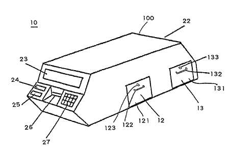
Figure 2 shows the appearance of the collection and
processing apparatus of the embodiment. Figure 3 schematically
shows the internal mechanism of the apparatus. ~ -
As shown in Figures ~ and 3, a cabinet 100 houses various
5 devices. Display and operation members are placed on one end of
the cabinet 100. The collection and processing apparatus has a
player data display 22l a personnel data display 23, a number-of-
recycled-cards display 24, and a number-of-discarded-cards
display 25 as display members. Also, the collection and
10 processing apparatus has a cardslot 26 and an input unit 27
provided with operation keys, including a ten-key numerical pad,
as operation members. .
The personnel data display 23 is made of, for example, a
liquid crystal display device for displaying information such as ~-
15 data re~orded on cards and messages of the collection and
processing apparatus for personnel in the gaming house. The -;
player~data display 22 is made of a liquid crystal display device ;~
like ~the personnel data display 23; it is placed on the end opposed
to the personnel data display 23. The number-of-recycled-cards
2 0 dlsplay 24 and the number-of-discarded-cards display 25 are ~ -:
each made of a liquid crystal display device. The number-of-
recycled-cards display 24 displays the current number of cards ;
recycled by the apparatus and stored in the recycled card stacker
13. The number-of-discarded-cards display 25 displays the
current nurnber of discarded cards determined to be unreusable by
the apparatus and stored in the discarded card stacker 12.
I 4 214181~
Further, provided on the side of the apparatus are a door 121
for taking out cards from the discarded card stacker 12 and a door
131 for taking out carcls from the recycled card stacker 13. The
door 121 is provided with a knob 122 and a keyhole 123. The door
5 131 is provided with a knob 132 and a keyhole 133.
As shown in Figures 3 and 4, the collection and processing
apparatus of the invention contains a main transport passage 17
for transporting cards input to the card slot 26 to the opposed end
and an input gate 14, a record data reader 15, a separation section
10 16, an eraser t8, a number-of-times writer 19, a cleaning section
20, and a power unit 28 placed along the transport passage 17.
Sensors 15S, 16S, 18S, and 19S for sensing card access are
placed on the entrance sides of the record data reader 15, the
separation section 16, the eraser 18, and the number-of-times
15 ~ writer 19 respectively. The power unit 28 is provided with a
backup ~attery (not shown).
;The collection and processing apparatus of the embodiment
has~a controller 110 for processing read data and controlling the
mentioned parts. The controller 110 comprises a central
~ . :
20 processing unit (CPU) 111 for executing operations, etc., a read-
only memory (ROM) 112 for storing programs, control constants,
messages, etc., a random access memory tRAM) 113 for
temporarily storing data of the operation results, etc., and an
interface 114. The programs stored in the read-only memory
25 (RQM) 112 include a program executing a procedure shown in .
Figure 5, for example. Connected to the controller 110 are the ~ ~
: ~:
-
~ 1 ~ 214181~
displays 22 to 25, the input unit 27, the input gate 14, the sensor ~.
15S, the record data reader 15, the sensor 16S, the separation
section 16, the sensor 18S, the eraser 18, the sensor 19S, and the
number-of-times writer 19.
At least a part of the RAM 113 is provided with a backup ~.` :
:
function with the battery of the power unit 28 when the power is
off (not shown). The data to be saved when the power is off, such ~ -
:~; as the data of the number of recycled cards and the number of
discarded cards, is stored in the battery backup area of the RAM
113. ~ .
The main transport passage 17 comprises a driving pulley -. ~....... .
~: ~ 172, a plurality of driven pulleys 173, a belt 171 placed on the
. ~ .. .
pulleys, rollers 174 disposed under the belt 171 for transporting
cards sandwiched between the rollers and the belt 171, and a
drive control mechanism of the driving pulley 172. Two sets of -
the pulleys 172 and 173 and the belt 171 are placed in parallel.
The placement gap is set narrower than the card width. The main .
transport passage 17 also has two guide rails 175 for supporting
cards. The roller 174 is placed between the two rails and has the
helght set so that~ a part of the outer peripheral surface of the
. : .
~roller slightly protrudes from the surface of the rails. ;
As shown in Figure 3, the input gate 14 consists of a pin
141 that can be made to appear and disappear as desired and an
actuator 142 for making the pin 141 appear and disappear, for
2~ example. The pin 141 is provided between the two belts 171 in
the card slot 26. When receiving a closing command from the
:
" ' :,
'' '~:-,
~ 1 6 2~4181~
controller 110, the actuator 142 causes the pin 141 to project
toward the main transport passage 17. On the other hand, when
receiving an opening command, the actuator 142 causes the pin
141 projecting to the main transport passage 17 to be withdrawn.
Each of th0 sensors 15S, 16S, 18S, and 19S, which is made
up of a light emitting diode and a photodiode (not shown), detects
access of a card by using the fact that light from the light
~; emitting diode to the photodiode is cut off when a card passes
between the diodes. The sensor 18S sends a detection signal to
the eraser 18. On the other hand, the sensors 15S, 16S, and 19S
send a detection signal to the controller 110.
For the record data reader 15, a reader fitted to the
recording mode of the recording media is used. In the
embodiment, it is made of a bar-code reader. Since three bar
codes are placed in parallel, as described above, in the
embodiment, the record data reader 15 is provided with three
read heads of a bar-code reader. The record data reader 15
generates nurnerical data from a signal output from the read
heads and sends the data to the controller 110.
~ T he separation device 16, which is disposed at an
intermediate point on the main transport passage 17, separates
., i
cards 3 transported on the main transport passage 17 upon
receipt of an instructibn from the controller 110. The separation
device 16 has a structure as shown in Figure 9, for example. That ~ ~
25 is, the separation device 16 comprises a branch rail 161 disposed :;
in place of a part of the guide rail 175, an actuator 163 for
::
~-- 1 7
21~181~
causing the branch rail 161 to pivot downward at a given angle
with one end as a supporting point and restoring the branch rail
161 to the former position, and a guide member 162 for guiding a
card 3 dropping from the branch rail 161 to the discarded card
stacker 12 when the branch rail 161 pivots downward. The -
actuator 163 causes the branch rail 161 to pivot to the angle at
~
which the card 3 completely drops, then restores the branch rail
161 to the former position. A roller 174 is secured to the branch
rail 161. ~;
The eraser 18 has an erasion head 181 placed at a position ~ -
opposed to the roller 174 and an erasion head drive circuit (not
shown). The erasion head 181 comes in contact with the
recording area of the card 3 and heats the area for erasing the
data recorded in the area. When a card access detection signal is ~ ~
received from the sensor 18S, the erasion head 181 of the eraser , ~'
'
18 is heated ~y the erasion head drive circuit.
The number-of-times writer 19 has a write head 191
~ ~ ~ placed at a position opposed to the roller 174 and a write head:~: drive circuit (not shown) for driving the write head 19. In the
2Q embodiment, the write head 191 generates a bar code. The write ;~
head 191 is provided at a position corresponding to a recording
area of number-of-card-recycle-times data. When receiving a
write instruction and the number-of-recycle-times data to be -
written from the controller 110, the number-of-times writer 19
writes a bar code representing the number of recycle times onto a `~predetermined area of the card.
;
-
I 8 2~41815
The data indicating the number of recycle times is recordedon the card in a bar code in the embodiment, but the invention is
not thus limited. Any record may be used if the number of recycle
times can be read from the record through the reader 15; for
5 example, it may be simple digits or binary magnetic data. Use of
magnetic data requires that a card should be provided with a
magnetic record area and that the record data reader 15 should
include a magnetic read head.
The cleaning section 20 is placed following the downstream ~'
10 end of the main transport passage 17. In the embodiment, the
~; cleaning section 20 comprises two cleaning buffs 201 and 201
placed at positions sandwiching a card. A rotation'drive
~ .
mechanism (not shown) for driving the cleaning buffs 201 and 201
for rotation is connected to either of them. The cleaning buffs
201 and 201 may be rotated with movement of''a card without
being connected to the rotation drive mechanism. In the
embod~iment, the cleaning section 20 operates independently of
the controller 110, but may be driven in response to a command
from the controller 110.
Next, the operation of the embodiment will be discussed
with reference to Figure 5.
When a switch (not shown) of the power unit 27 is turned
on, the power unit'27 supplies power to the collection and
processing apparatus 10 for placing the apparatus 10 in an :
2 5 operation state.
~':'' ~.,.
. ~'., '~
19 ~181~
The CPU 111 of the controller 110 first checks to ensure
that each of the stackers 12 and 13 has a capacity at step 1001
by looking at the data storage areas of the number of recycled
cards and the number of discarded cards in the RAM 113.
If at least one of the staskers 12 and 13 has no card
capacity, the CPU 111 causes the personnel data display 23 to
~ ~ dis:play~ a message indicating the stacker name of the stacker and
j~ ~ requesting person~nel ts remove cards from the stacker and resetthe system after taking out the cards at step 1002. That is, the
10 CPU 111 reads a message corresponding to the decision made at
~ . ~
~ step i001 from the ROM 112, converts the message into image ~ - ~
- .
data by using font data stored in the ROM 112, and sends the
~ ~ .
image data to the personnel data display 23 for displaying the
message. If the message is expanded to an image, which is stored
in the ROM 112, the step converting the message into the image
- data is~ not required. Therefore, in this case, font data need not be
provided~ either.
Next, the CPU 111 determines whether or not a resst
operation has been performed through the input unit 27 at step
1003.~ If a reset operation is performed, the CPU 111 clears the ~-
data of the number of recycled cards and the number of discarded
cards stored in predetermined areas of the RAM 113 at step 1004.
Then, control returns to step 1001.
In this condition, if both the stackers 12 and 13 can store
: ~ :
additional cards, the CPU 111 sends a command opening the card
input gate 14 to the card input gate 14 at step 1005, whereby at
. ~:
~ .
2i41815
the card input gate 14, the actuator 142 operates to withdraw the
pin 141 from the main transport passage 17. Also, the CPU 111
reads a message indicating that cards can be input from the ROM
112 and sends it to the personnel data dispiay 23 for displaying
the message.
In this condition, the CP'J 111 checks whether or not a
signal indicating detection of card access is input from the
sensor 15S at step 1006. If the detection signal is input, the CPU
111 instructs the record data reader 15 to read information
recorded on the card at step 1007, then reads the information
from the reader 15 and transfers necessary data to a
predetermined area of the RAM 113.
The CPU 111 checks the read data for error at step 1008.
For example, if a parity bit is added, the bit is checked; if ECC is
~ ~ l S added, it is checked. If an error is detected, the record on the
;~ card is low in reliability, and the card is discarded. If the issuing
machine does not have an error check bit addition function, the
` step may be omitted.
When no error is detected, the CPU 111 determines whether
or not the number of recycle times reaches a predetermined
number of times at step 1010. The card reaching the prescribed
,
number of times is not reused and is discarded. Durability of
cards is previously examined by experiment, etc., to define the
prescribed number of times. For example, it is defined as 50.
If the number of recycle times does not reach the prescribed
number of times, the current recycle time is added for calculating -~
~,
. ,~ ....
'~
,. ~ .
.~ .,. ~ -
.., - .~ -
:
2 1 21~815
.
the cumulative number of recycle times of the card at step 1011.
That is, 1 is added to the number of recycle times read through
the record data reader 15 to update the number of recycle times.
Also, the number of recycled cards is calculated at step 1012.
5 That is, the data of the number of recycled cards stored In the
RAM 113 is read and is incremented by one to update the number
of recycled cards. The updated number of recycled cards is stored
in the predetermined area of the RAM 113.
In this condition, the separation section 16 does not ~ ~ -
10 perform special processing for the card. The eraser 18 erases the
data recorded on the card. That is, when the sensor 18S detects a
card access, it sends a detection signal to the eraser 18, which
then drives the erase head 181 for erasing the data recorded on
the card.
Meanwhile, the CPU 11t monitors a detection signal from
the sensor 19S at step 1013. ~;
Here, if a card access detection signal is input from the
sensor 19S, the CPU 111 sends a command for writing the number
sf recycle times and the new found number-of-recycle-times data
20 to the number-of-times writer 19 at step 1014. When receiving
the command and the data, the number-of-times writer 19
displays a bar code representing the number of times for the card -
in the card area into which the number of times is to be written.
The card arrives at the downstream end of the main transport
25 passage 17, is then passed through the cleaning section 20 and
~-:
.~ ~ . . . . .
, _
2? 2~4181~
: .`
sent to the recycled card stacker 13. The CPU 111 returns to step
1 001 .
On the other hand, if an error is detected or the number of
recycle times reaches the prescribed number of times, the number
5 of discarded cards is calculated at step 1015. That is, the data of
the number of discarded cards stored in the RAM 113 is read and
is incremented by one to update the number of discarded cards.
The found value is stored in the RAM 113.
The CPU 111 monitors a detection signal from the sensor
10 16S at step 1016. When receiving a detection signal from the
sensor 16S, the CPU 111 instructs the separation section 16 to -
place the card out of the main transport passage 17 at step 1017.
Whe~n receiving the instruction, the separation section 18
operates the actuator 163 for causing the branch rail 161 to pivot
so that the downstream tip of the branch rail 161 fa!ls downward
with~ the~ upstream end as a supporting point, whereby the card on
the branch ~rail is dropped. The card drops along the guide member
162~ and is stored in the recycled card stacker 1.
Thus,~if the number of reference times is appropriately set
20 ~ as ~described above, cards 3 damaged, etc., can be automatically `:~
discarded efficiently. Since the eraser 20 and the cleaning means
21 are disposed on the main transport passage 17, data :~
initiallzation and cleaning of cards 3 to be reused are also
performed automatically.
:: ~.
: ~;
:.` . ; . l .
...~
........
...~- ;. :
-: .... .;..
. . ..
: .. ..
; ,