Note: Descriptions are shown in the official language in which they were submitted.
This invention relates in general to a programmable remote control transmitter
and more particularly to a remote control transmitter in which the ability to
program
the transmitter may be selectively permitted or denied.
As the number and variety of television transmissions has increased, the need
1 o to restrict and supervise the television viewing by children has also
increased. At a
young age children are able to learn to use remote control transmitters to
turn
television sets on and off and to select channels. When parents are not
present,
children are able to change channels which carry programs which may not be
considered appropriate for children.
t 5 Devices exist which are aimed at controlling the amount of television that
a
child may watch. For example Recoton Canada Ltd. markets a product having a
switch which is connected between the television and the cable or antenna
supplying
the signal to the television. The television is only able to be operated when
the switch
is turned on. When the switch is offthe television screen is blank. The device
cannot
2o be disconnected without the use of a key.
Such devices do not address the situation where a child is permitted to watch
television but restrictions on the types of progcaals which the child may view
are
imposed by a parent or other caregiver.
Thus a programmable remote control transmitter which permits access to a
programmer-defined set of television channels which set may not be altered by
a
child, is desirable.
An object of one aspect of the present invention is to provide an improved
programmable remote control transmitter.
In accordance with one aspect of the present invention there is provided a
programmable remote control transmitter for controlling an electrical device,
the
1o remote control transmitter having a programming mode and a controlling
mode,
comprising memory means for storing a predetermined maximum number of remote
control codes, a keypad for selecting a one of the stored remote control codes
when
the remote control transmitter is in the controlling mode, the keypad
operatively .
connected to a transmitting device for transmitting remote control signals
t 5 corresponding to the selected remote control code to the electrically
device, means for
inputting remote control codes to the memory means only when the remote
control
transmitter is in programming mode, and means for selectively permitting the
remote
control transmitter to be placed in programming mode.
Preferably, the programmable remote control transmitter has a means for
20 selectively permitting the remote control transmitter to be placed in
programming
mode which comprises a locking mechanism integral the programmable remote
control transmitter and a removable key.
Preferably, the programmable remote control transmitter may control a
television receiver.
. 2
21~2~2~
Preferably, a programmable remote control transmitter is provided such that
each key on the keypad corresponds to a unique one of the stored remote
control
codes.
Preferably, the programmable remote control transmitter which has a
maximum number of six remote control codes.
Preferably, the programmable remote control transmitter further comprises
keys which are specifically assigned to control the on and off fiuiction of
the electric
device.
Preferably, the programmable remote control transmitter has means for
to controlling the on fimction of the electric device which is operatively
connected to the
means for transmitting the remote control signal such that immediately
following the
transmission of the remote control signal the electric device is placed in the
"on"
mode, a second remote control signal is transmitted corresponding to a
specified one
of the remote control codes stored in the memory means.
15 Preferably, the programmable remote control transmitter has a keypad which
is of a large size such that operation of the remote control is easily carried
out by
children.
Preferably, the programmable remote control transmitter has a means for
inputting remote control codes comprising a means for receiving signals from a
2o second remote control transmitter and means for storing such signals in the
memory
means.
Preferably, the programmable remote control transmitter has a battery
compartment which is lockable and whose key is also used to switch the
transmitter
from programming to controlling mode.
~~4~~~
Advantages of the present invention are: a programmable remote control
transmitter is provided which stores a predetermined number of remote control
codes
and which may only be reprograrnmed when the remote .control transmitter is
placed
in programming mode, and for which key access is required to place the remote
control transmitter in programming mode.
A detailed description of the preferred embodiment is provided herein below
with reference to the following drawings, in which:
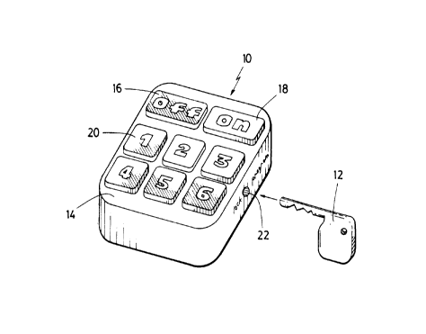
1o Figure 1, in a perspective view, illustrates a programmable remote control
transmitter in accordance with the preferred embodiment of the present
invention;
Figure 2, in a side elevation view, illustrates the programmable remote
control
transmitter of Figure 1.
Figure 3, in a front elevation view, illustrates the programmable remote
15 control transmitter of Figure 1.
Figure 4, in a perspective view, illustrates the bottom surface of the
programmable remote control transmitter of Figure 1.
Figure 5, in a partial cut-out perspective view, illustrates the locking/mode
switching mechanism of the programmable remote control transmitter of Figure I
.
2o In the drawings, the preferred embodiment of the invention is illustrated
by
way of example. It is to be expressly understood that the description and the
drawings
are only for the purpose of illustration and as an aid to understanding, and
are not
intended as a definition of the limits of the invention.
4
CA 02142025 1998-07-06
Detailed Description of the Preferred Embodiment
In Figure 1, a programmable remote control transmitter of the preferred
embodiment of the invention is shown in a perspective view. The programmable
remote control transmitter 10 has an associated key 12. A keypad 14 is
provided on
the upper face of the remote control transmitter. The keypad 14 has an off
button 16
and an on button 18 as well as six numerically marked buttons 20. A locking
mechanism having a keyhole 22 is provided in the side of remote control
transmitter 10.
Turning to Figure 2, the remote control transmitter of Figure 1 is shown in a
1 o side elevation view showing the side portion of the transmitter having
keyhole 22. On
button 18 is shown in profile, as are two of the numeric key pad buttons 20.
Figure 3 shows the remote control transmitter of Figure 1 in a front elevation
view. Off button 16 and on button 18 are shown in profile. Infrared
transmitter/receiver 24 is shown located on the front vertical panel of the
remote
control transmitter.
Figure 4 shows the bottom surface 26 of the remote control transmitter of
Figure 1 in a perspective view. The body of the remote control transmitter has
top
portion 28 and bottom portion 30 which are fastened together by screws 32. The
remote control transmitter has a battery compartment panel 34 which has lock
36.
2o Behind the panel 34 are located batteries 38, 42, shown in dotted outline
in Figure 4.
Figure 5 shows the locking/mode switching mechanism of the remote control
transmitter of Figure in a partial cut-out perspective view. Key 12 is shown
in
keyhole 22. Keyhole 22 has a radially extending slot 44. Bit 46 of key 12 is
able to
be inserted into slot 44. Spring 48 is seated at the end of keyhole 22. Switch
50 is
5
CA 02142025 1998-07-06
located having a trip mechanism in slot 44. Switch 50 is connected to the
electronic
circuitry of the remote control transmitter, shown symbolically in Figure 5 as
stylized
computer chip 52.
In operation, the remote control transmitter of the invention is put in
programming mode by key 12 being inserted in keyhole 22 and by the key then
being
turned to the programming position (corresponding to the "program" label
adjacent to
keyhole 22). While the key 12 is turned to the programming position, a second
remote control transmitter (usually the one which has been provided by the
manufacturer of a particular television set) is placed facing the remote
control
1o transmitter 10 such that the transmitting window of the manufacturer's
remote control
transmitter (not shown) is facing infrared transmitter/receiver 24 of remote
control
transmitter 10. One of the six numeric keys 20 is depressed on the remote
control
transmitter 10 while at the same time the manufacturer's remote control
transmitter is
manipulated in the way that normally selects a desired channel on the
television set.
15 The remote control transmitter 10 reads the signal from the manufacturer's
remote control transmitter and saves the signal as a remote control code in
the
memory of the remote control transmitter 10. The circuitry to accomplish the
function
of reading and storing such signals and codes is well-known in the art.
While the key 12 is in the programming position, this procedure may be
2o repeated for other buttons in the numeric keypad 20. Thus a predetermined
number of
remote control codes (in the case of the preferred embodiment up to six) are
stored in
the memory of remote control transmitter 10. Multiple buttons may also be
programmed with the same remote control code. In this way the device may
restrict
6
~14~~ ~~
access to fewer than six channels. The key 12 is then fumed to the position
corresponding to the "lock" label on the remote contml transmitter 10 and
removed.
Placing bit 46 of key 12 in slot 44 can only be accomplished by exerting a
force against the spring 48, shown in Figure 5. Bit 46 will be inserted in
slot 44 and
will engage switch 50. By engaging switch 50, circuitry 52 of the programmable
remote transmitter will be placed in controlling mode or programming mode
described below.
When the lock is in the "lock" position, it is no longer possible to program
the
remote control transmitter 10 to save further remote control codes in the
memory.
t0 Switch 50 interacts with circuitry 52 so as to cause the circuitry to no
longer enable
programming of the remote transmitter to occur. Switch 50 is a toggle switch.
The
circuitry which permits this selective operation of the device is well-known
in the art.
When the key is removed from the remote control transmitter 10 after having
been in
the "lock" position, the device is in "controlling" mode.
15 A similar procedure is carried out to ensure that the proper codes for the
on
and off buttons 18, 16 are stored in the memory of the remote control
transmitter 10.
Likewise, one or more of the numeric buttons 20 may be reprogrammed at a later
date
to change the codes associated with the one or more buttons.
As referred to above, when the lock of the remote contml transmitter is in the
20 "lock" position, the remote control transmitter 10 is said to be in
"controlling mode".
When in controlling mode it is possible to turn the television set off and on
using off
and on buttons 16 and 18, respectively. In addition, the remote control code
stored in
the memory may be accessed using one of the six buttons 20. For each remote
control
code stored in memory a single button is able to access the remote control
code and
CA 02142025 1998-07-06
result in a remote control signal being transmitted from infrared
transmitter/receiver
24 to the television set to be controlled.
As will be apparent, this device is appropriate for children from two years of
age and up. In the preferred embodiment the remote control transmitter 10 is
manufactured of a shock-resistant plastic material with brightly coloured
housing and
a large colourful keypad 14.
According to the preferred embodiment, when the on button 18 is depressed,
circuitry in the remote control transmitter 10 automatically transmits through
transmission infrared transmitter/receiver 24 a remote control signal
corresponding to
1o the remote control code stored in association with the "1" button of the
numeric
buttons 20. This prevents children from using the remote to turn on and watch
a non-
programmed channel on a television which has been left by another user tuned
to a
channel not suitable for children. Circuitry to provide such a function is
well-known
in the art.
A further element of the preferred embodiment of the invention is that the
remote control transmitter will prevent a child from changing channels to
rapidly. If
the number of channels selected within a given time period exceeds a specific
limit,
the remote will lock on to a preprogrammed TV channel and prevent further
changes
during what is referred to as a "time out".
A further aspect of the preferred embodiment locks batteries into the remote
control transmitter 10. As shown in Figure 5, batteries 38, 42 are located
behind panel
34. A locking mechanism 36 is provided which is operable by key 12. Thus the
same
key which operates the lock/switching mechanism is used to lock batteries 38,
42 into
the device.
8
In summary, a remote control transmitter is provided which enables a parent or
other caregiver to program a specific number of remote control codes into a
remote
control transmitter in order to restrict the television viewing of a child,
while
permitting the child to choose between a certain number of permitted
alternatives.
Other variations and modifications of the invention are possible. For example,
the number of remote control codes which may be programmed into the remote
control transmitter may be fewer or greater than six. All such modifications
or
variations are believed to be within the sphere and scope of the invention as
defined
by the claims appended hereto.
to
9