Note: Descriptions are shown in the official language in which they were submitted.
2142115
y
M&C FOLIO: 545P66163 WANGDOC: 02030
APPARATUS FOR MANUFACTURING A TRUSS
The invention relates to apparatus for manufacturing
a truss, a press head for use therein and a method of
connecting timber members together.
Until recently, roof trusses have exclusively been
manufactured manually. However, over the years, various
developments have been made which have assisted in the
manufacturing process. For example, machines having a
plurality of press heads each having an integral platen
have been developed wherein the press heads and platens
are manually positioned at the joints of the truss and,
locked in po:aition. The members forming the truss are
positioned on the platens and all of the press heads are
then operated simultaneously and from a central control
to press connectors into the joints to form a self
supporting structure. Another type of known jig
consists of separate platens and press heads wherein the
platens are :first laid out at their required joint
locations (often they are strung together to form long
continuous suctions for ease), and suspended or floor
mounted press heads are then individually moved into
position at ~aach joint and operated. A further type of
known jig consists of a solid roller used to press
connector plates into the joints. The plates are
E~10~0 St~~~'~
WO 94/03312 21 ~ 211 ~ PGT/GB92/01480
2
loosely fixed at the joints by hammering and then the
entire truss assembly is fed into the roller mechanism
which acts rather like a mangle to press the connectors -------- -=--
into the joints and fix the truss members together.
It is also known to provide a large truss table
whereon stops are manually located at required
positions, continuous platens are laid at and between
all joints and then a travelling beam press traverses
the truss stopping at each joint under manual control
and presses the jof nts together. US patent No. 4943038
discloses a similar truss assembly table having a
plurality of f:ectio:ns in each of which a plurality of
jig stops is provided which can be positioned to enable
the truss members to be accurately positioned with
respect to ones another on the table prior to
connection. ~~he jig stops are each positioned by means
of a lead screw driven by a manually operated drill.
However, although each jig stop is positioned by a
power-operated device, these devices are manually
operated and esach jig stop therefore requires individual
attention.
The known apparatus for assisting in the manufacture
of trusses is therefore time consuming to operate and
labour intensive. ~'he average time taken to set up
suitable apparatus for manufacturing a run of identical
trusses is half an hour to an hour. Pressing a run of 8
to 10 trusses will also typically take about half an
2142115
3
hour. Thus the setting up of the jig usually occupies
at least 50% of the production time and hence a
considerable proportion of the cost. It is an object of
the present invention to provide apparatus which enables
a truss to be accurately and swiftly manufactured. It
i:s a further obj ect of the invention to reduce the
labour costs involved in manufacturing trusses.
The invention provides apparatus for manufacturing a
truss, comprising a plurality of press heads arranged- in
a single plane about a fixed datum point and movable
within the p:Lane about the datum point, wherein the
press heads are each connected to powered driving means
and to control means for controlling the powered driving
means and for automatically determining the desired
position of eaach head with respect to the datum point
such that each head can be automatically driven to its
desired position, characterised in that each press head
comprises-ta platen and a retractable trolley, each
trolley having a trolley head and being movable between
a retracted position wherein the upper surface of the
trolley head is level with or below the upper surface of
the platen, a.nd an operating position wherein the lower
surface of th.e trolley head is located above the upper
surface of the platen so that, when the trolley is in
the operating position, the platen can be raised towards
the trolley head to carry out a pressing action on-any
truss members and connectors located therebetween.
!~ ..1 yi....r.t..
r
p"r~=!v~~y
21~211~
4
Preferably, the platens and trolleys are all
simultaneously operable, although it is envisaged that
the platens and trolleys can be selectively operable
according to the truss to be manufactured. Pre era y,
each press head is rotatable about an axis perpendicular
to the single plane with respect to the support
structure on which it is mounted.
Preferably, the apparatus further comprises an
automatic feeding device for automatically feeding
connectors to the press heads. This speeds up the
operation of the apparatus to manufacture a number of
trusses of a given configuration.
The invention also provides a press head for use in
apparatus fo:c manufacturing a truss, comprising a platen
and a retracl:able trolley, the trolley having a trolley
head and being movable between a retracted position and
an operating position, characterised in that, in the
retracted position,, the upper surface of the trolley
head is level. with or below the upper surface of the
platen and, i.n the operating position, the lower surface
of the trolley head is located above the upper surface
of the platen so that, when the trolley is in the
operating position, the platen can be raised towards the
trolley head to carry out a pressing action on any truss
members and connectors located therebetween.
Preferably, the trolley is Located adjacent the platen
when in the retracted position and the upper surfaces of
~MEN~ED SH''-~~
2142~.~.5
the trolley head and the platen are substantially
coplanar. ~~lso, :it is preferred if frame members are
attached to the platen along at Least one side thereof
to allow connectors to be placed freely between~e ------- -
upper surface of the platen and the truss members to be
used to form a truss, the connectors being pressed into
the truss members on operation of the press head. More
. preferably, the frame members are attached to the platen
along three sides thereof, the platen being preferably
rectangular in shape. This avoids the need for the
truss members to x:est on the connectors which can lead
to instability of the truss members during manufacture
and movement of the connectors away from their desired
positions before pressing occurs.
It is preferred that the frame members are
retractable during' operation of the press heads to a
position wherein the frame members do not project above
the upper surface of the platen.
In an advantageous embodiment, the frame members are
releasably attached to the platen.
In an advantageous embodiment of the invention,
holding means are located directly or indirectly on the
platen for holding at least one timber member in place
with respect to the platen during operation of the press
head. Preferably, the holding means are retractable
during operas=ion of the press head to a position wherein
the holding means do not project above the upper surface
212115
6
of the platen. Furthermore, it is preferable if the
holding means comprise at least one pneumatically
operated cy:Linder clamp arranged to press against a
respective 'timber member to hold the said timber member
in place. :Cdeally, the holding means are mounted on the
frame members located on the platen. _
The invention also provides apparatus for connecting
a plurality of timber members comprising a fixed
pressing member, a platen movable with respect to the
pressing member and means for introducing at least one
connector beaween the pressing member and the platen,
characterised in 'that the platen and/or the pressing
member compi:ise magnetic holding means for holding the
or each connector in place during movement of the
platen. Preferably, the holding means comprise
electromagnEas located in or on the platen and/or the
pressing member. The means for introducing at least one
connector between the pressing member and the platen are
preferably arranged to deliver connectors therebetween
in pairs. More preferably, the connectors comprise
pairs of gar.~g-nail plates arranged so that the nails of
each plate interengage with the nails of the other
plate. When the platen is moved away from the pressing
member, one connecaor of the pair is held on each of the
platen and the pressing member until connection of the
timber members tales place.
The invention also provides a method of connecting
P~MENOED SNEE~t
CA 02142115 2000-09-25
WO 94/03312 PCT/GB92/0i4$0
7
timber members together utilising apparatus as described
above comprising the steps of:
(a) moving the platen to a connector-receiving
position with respect to the fixed pressing member;
(b) introducing a pair of gang-nail connectors to
the space between the platen and the pressing member;
(c) actuating electromagnets located in or on the
platen and the pressing member to hold one connector
against the platen and one connector against the
pressing member;
(d) moving the platen and the respective connector
held thereagainst away from the pressing member and the
other respective connector to a retracted position;
(e) introducing the timber members to be connected
to the space between the platen and the pressing member;
(f) moving the platen towards the pressing member so
that the connectors held against the platen and pressing
member are pressed into the timber members;
(g) deactivating the electromagnets to release the
timber members from the apparatus and moving the platen
away from the pressing member; and
(h) removing the timber members from the apparatus.
Embodiments of the invention will now be described
with reference to the accompanying drawings wherein:
Figure 1 is a schematic diagram of apparatus
according to a first embodiment of the invention;
Figure 2 is a schematic diagram of apparatus
CA 02142115 2000-09-25
WO 94/03312 PCT/GB92/01480
8
according to a second embodiment of the invention;
Figure 3 is a perspective schematic view of a press
head forming part of the apparatus of either of Figures
1 and 2;
Figures 4a, 4b, 4c and 4d are schematic diagrams
showing the operation of the press head of Figure 3;
Figure 5 is a schematic sectional view of a clamping
device used in the apparatus of any of Figures 1 to 4;
Figure 6 is a schematic sectional view of an
alternative clamping device for use in the apparatus of
any of Figures 1 to 4;
Figure 7 is a plan view of a platen forming part of
a press head with frame members mounted on three sides
thereof;
Figure 8 is a schematic view of a pneumatic clamp
for use in the apparatus of any of Figures 1 to 4;
Figure 9a is a schematic sectional view of a frame
for attachment to the platen of Figure 7;
Figure 9b is a schematic front view of part of the
frame of Figure 9a; and
Figures l0a to IOd are schematic views of apparatus
for connecting timber members incorporating a device for
automatically feeding connectors to the press head.
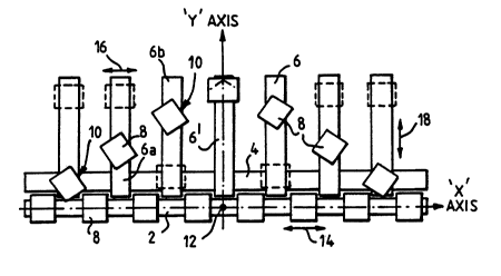
The apparatus illustrated in Figure 1 comprises a
transversely extending support structure 2 and a
transverse track 4 extending parallel to the support
structure 2. A plurality of longitudinally extending
CA 02142115 2000-09-25
WO 94/03312 PCT/GB92/01480
9
support structures 6 are arranged so that one end 6a of
each support structure 6 is supported on and movable
along the track 4. The opposite end 6b of each. support
structure 6 is supported on a wheeled carriage (not
shown) or other suitable supporting means allowing each
support structure to move along the track 4.
A plurality of press heads 8 are mounted upon the
support structures 2,6. The transverse support
structure 2 carries a plurality of press heads, a total
of eight being illustrated in Figure 1. Each of the
longitudinally extending support structures 6 is shown
carrying two press heads 8 except for the central
support structure 6' which carries only a single press
head. However, each support structure 6 can carry any
number of press heads (typically between one and
three). Furthermore, the press heads are removable from
the support structures 6 so that any one support
structure 6 can have press heads added or removed to
suit any particular design requirement. Each press head
8 located on the longitudinally extending support
structures 6 is rotatable about an axis 10 located
substantially centrally of one edge of the press head
(see Figure 7). The press heads located on the
transversely extending support structure 2 need not be
rotatable but can be if so desired. Each press head 8
is furthermore slidably movable along the respective
support structure 2,6 so as to vary its position
CA 02142115 2000-09-25
WO 94/03312 PCT/GB92/01480
therealong. Driving means for carrying out the sliding
movement are provided, but not shown for reasons of
clarity. Driving means (not shown) are also provided
for moving the support structures 6 along the track 4.
The central point of the transversely extending
support structure 2 is designated the datum point 12.
This datum point can be fixed at any suitable point
within the overall geometry of the apparatus or, indeed,
outside if desired. It is not necessary for the datum
point to be fixed as illustrated in Figure 1, but it is
convenient to fix the datum point at a specific point
along the transverse support structure 2. An X axis and
a Y axis have also been illustrated in Figure 1 to
assist in the description of the apparatus set out
below. The X and Y axes intersect at the datum point
and the X axis extends along the transverse support
structure 2 and the Y axis extends parallel to the
1 ongi tudi nal l y extendi ng s upport structures 6.
The apparatus of the invention also incorporates
control means (not shown) which operate to drive the
driving means and so to position the press heads 8
appropriately to manufacture a truss of a particular
shape. The position of all joints in the desired truss
relative to the datum point are input into the control
apparatus. The control apparatus then determines, by
means of monitoring and comparative devices (not shown),
the difference between the actual position of each press
CA 02142115 2000-09-25
WO 94/03312 PCT/GB92/01480
11
head 8 and its desired position in order to manufacture
the required truss. The control means then actuates the
driving means to alter the position and orientation of
each press head 8 in response to the value of the error
between the actual position of the press head 8 and its
desired position. The driving means are arranged to
move the press heads 8 located on the transverse support
structure 2 along the support structure 2 in the
direction of arrow 14 to their desired positions; to
drive the support structures 6 in the direction of arrow
16 to locate the press heads 8 mounted thereon in their
correct "X axis" positions with respect to the datum
point; and to move the press heads 8 mounted on the
support structures 6 in the direction of arrow 18 in
order to achieve the correct "Y axis" position of each
press head 8 with respect to the datum point 12. Once
the desired positions of each press head are received by
the control means, then each press head 8 can be moved
by the control means to its desired position. The press
heads can be moved in pairs, in groups or all together
which reduces the amount of time required to set up the
apparatus to produce a specific truss. The control
means is also capable of rotating the press heads 8
about their axes 10 to align the press 8 heads in the
direction of the members which will form the truss.
Once all of the press heads are correctly positioned,
they can be held in those positions by an automatic
CA 02142115 2000-09-25
WO 94/03312 PCT/GB92/01480
12
braking system (not shown).
For safety reasons, a system of lights and/or sirens
(not shown) can be used to reduce the risk of accident
or i nj ury to pers ons near the j i g. Red li ghts are
arranged to light up or flash when the press heads 8 are
moving or in operation. Hooters and sirens are also
sounded. Also, an automatic stop and reverse system is
provided to reduce the risk of accidents. Indicators
(not shown) are provided on each press head 6 to show
when the respective press head 8 is in the required
position. A red light indicates an incorrect position,
an amber light indicates that the error is within
certain limits and a green light shows that the press
head is positioned correctly. This enables the press
heads to be manually positioned, if necessary, when for
example the driving means are for any reason inoperable.
Figure 2 shows an alternative arrangement according
to the invention similar to that shown in Figure 1 but
omitting the transversely extending support structure.
The only support structures provided are those extending
longitudinally 6. As described above, the support
structures 6 are movable along the track 4. The datum
point 12 is relocated to the intersection of the track 4
and the centre support structure 6' which may, if
desired, be fixed ;with respect to the track 4. The X
and Y axes are also relocated to pass, respectively,
parallel and perpendicular to the track 4 and through
CA 02142115 2000-09-25
WO 94/03312 PCT/GB92/01480
13
the datum point 12. As with the apparatus of Figure 1,
the datum point can in fact be located at any convenient
position with respect to the jig.
Press heads 8 are mounted on the support structures
6 in sufficient numbers for at least one press head 8 to
be positioned at each joint of the truss to be
manufactured. Press heads are positioned near the track
4 to deal with joints located on the bottom chord of the
truss. Alternatively, the truss could be manufactured
"upside down"; i.e with the bottom chord extending
parallel to the track 4 but adjacent the opposite ends
of the support structures 6 to those mounted on the
track.
This embodiment is even more versatile than the
apparatus described above and facilitates the
a~~anufacture of trusses having bottom chords which are
angled or which contain non-parallel sections. It is
envisaged that this type of apparatus will require a
larger number of support structures 6 than would be
required by the apparatus of Figure 1 to accommodate the
number of joints commonly required along a bottom chord.
Both of the embodiments of Figures 1 and 2 utilise
identical press heads 8. Each press head 8 is
substantially as shown in Figures 3 and 4. Figure 3
shows a press head in its operational configuration.
The press head 8 consists of a platen 20 and a trolley
22. The trolley 22 is movable between a retracted
CA 02142115 2000-09-25
WO 94/03312 PCT/GB92/01480
14
position (shown in Figure 4a) and an operational
position (shown in Figures 3 and 4c). Suitable
mechanical means by which the trolley 22 can be moved in
relation to the platen 20 are well known and will not be
described here.
A frame 24 (shown in dotted lines in Figures 3 and
4) is attached to the platen 20. The frame itself and
the means of connection will be described below. The
purpose of the frame 24 is to allow a space between the
upper surface 26 of the platen 20 and the lower surface
of a truss member 28 positioned on the press head 8
during the manufacturing process.
The manufacturing process will now be described.
when the press heads 8 have been correctly
positioned by the control means, the truss members can
be positioned on the apparatus shown in Figure 1 or 2.
This involves laying truss members 28 across the frames
24 of each press head 8 and holding them in place by
means of pneumatic timber clamps and stops (described
below). A connector 30 is positioned on the upper
surface 26 of the platen in the space between the platen
20 and the truss member 28. A further connector 32 is
positioned on top of the truss member 28. A signal is
then given by the operator via the control means to
commence the pressing operation and warning sirens and
lights are operated. The trolley 22 is initially in its
retracted position, being located adjacent the platen 20
CA 02142115 2000-09-25
WO 94/03312 PCT/GB92/01480
with the upper surface 34 of the trolley head 36
substantially level with the upper surface 26 of the
platen. The trolley 22 is then moved upward as shown in
Figure 4b and subsequently transversely so that the
trolley head 36 is located directly above the platen
20. The trolley head 36 is also located above the truss
member 28 and the two connecting members 30,32. The
final step of the pressing operation is to raise the
platen 20 with respect to the trolley 22 with sufficient
force to press the connectors 30,32 into the truss
member 28. The pressing motion is automatically ended
when a sufficient force has been applied for a
predetermined time. The lifting mechanism by means of
which the platen 20 is raised is preferably
hydraulically operated and controlled by the same
control means used to position the press heads 8. By a
reversal of the steps just described, the trolley 22
returas to its retracted position adjacent the platen 20
and the pneumatic timber clamps are automatically
released to facilitate rapid handling of the truss off
the j i g.
Each of the press heads 8 is operated in an
identical manner. If all of the press heads 8 are being
used to manufacture a particular truss, then all of the
press heads will be operated at the same time. If,
however, there are a number of press heads which are not
required in the manufacture of a particular truss, then
CA 02142115 2000-09-25
WO 94/03312 PCT/GB92/01480
16
the control means will select only the press heads which
are required and will not operate those which are not
required.
The frame 24 mentioned above is necessary to allow a
connector to be positioned beneath the truss member 28
without rendering the truss member unstable with respect
to the apparatus. In some cases, it will be necessary
for two press heads 8 to be located very close to one
another and it may be necessary for part or all of the
frame surrounding any particular platen 20 to be
removed. For any one platen or group of platens,
sufficient frames will be needed to adequately support
the timber to be connected. In order to achieve this, a
clamping device such as that illustrated in Figure 5 is
utilised. The device consists of a housing 40 in which
is slidably located a cylindrical member 42 carrying a
projecting member 44. The projecting member 44 carries
bayonet catches 46 which are locatable in cammed grooves
48 formed in the side walls of the platen 20. A disc
spring 50 is located between the end wall of the housing
40 and the adjacent face of the cylindrical member 42
and the spring 50 biases the projecting member 44 into a
retracted position. The cylindrical member 42 is
retained in the housing by means of a handle member 52
rotatably fixed to the cylindrical member 42; the handle
member 52 abuts against a disc shaped member 54 which is
securely fixed by means of a split ring in the housing
CA 02142115 2000-09-25
WO 94/03312 PCT/GB92/01480
17
40. The frame 24 is non-releasably mounted on the
projecting member 44 between the housing and the bayonet
catches 46. The clamping device and the frame--24 cannot
therefore be separated.
In order to securely clamp the frame 24 onto the
platen 20, the projecting member 44 and the bayonet
catches 46 are introduced into the cammed grooves 48 in
the platen 20 to bring the frame 24 into abutment with
the platen 20. The handle 52 is then rotated so that
the bayonet catches 46 engage with the cammed surface of
the grooves 48. As the bayonet catches 46 travel along
the cammed grooves 48, the projecting member 44 is
forced into an extended position against the bias of the
spring 50. The movement involved is, in fact, very
slight. This type of clamping device can be used to
rapidly achieve a high clamping force without risking
damage to the clamping device, or to the components
being clamped, by overtightening. The frame 24 can be
easily and quickly removed from the platen if desired
merely by rotation of the handle 52 in the opposite
direction to that required for connection, followed by
removal of the projecting member 44 from the cammed
groove 48.
Figure 6 shows a variation of the connector shown in
Figure 5 adapted for connection to a frame 24 so that
the housing 40 can act as a stop member to assist in
positioning the timber member on the platen. The
CA 02142115 2000-09-25
WO 94/03312 PCT/GB92/01480
18
connector itself is virtually identical with the
connector shown in Figure 5 but has a slightly longer
projecting member 44 on which is mounted a clamping
member 60 having internal rammed grooves 62. The
bayonet catches 46 are arranged at the ends of these
rammed grooves 62. The clamping member 60 is
rectangular in shape, although any non-circular shape
would be adequate.
The operation of the clamping device as a stop is as
follows: The projecting member 44 and clamping member
60 are introduced into a slot 64 running the length of
an appropriate frame 24 by means of one of two keyways
66 appearing at either end of the slot 64 (see Figure
7). The stop is then slid along the slot 64 with the
frame member 24 located between the clamping member 60
and the housing 40. When the desired position has been
reached, the handle 52 is rotated to cause the bayonet
catches 46 and the clamping member 60 rotate as well.
The clamping member 60 will, after a certain amount of
rotation, abut against the frame 24 due to the
non-circular shape of the clamping member. Further
rotation of the handle 52 will cause the bayonet catches
46 to travel along the rammed grooves 62 and thus force
the projecting member 44 into an extended position
against the bias of the spring 50. A high clamping
force between the housing 40 and the clamping member 60
is thereby achieved without undue effort and without a
CA 02142115 2000-09-25
WO 94/03312 PCT/GB92/01480
19
risk of overtightening. The stop is thereby accurately
and easily located on the frame 24 and can, if required,
be accurately and easily relocated.
The connector described above in relation to Figures
and 6 is extremely versatile. For example, the
connector can be adapted to receive pneumatic holding
stops for assisting in the location and gripping of
timber members in relation to the platen. Ideally,
pneumatic cylinder stops as illustrated in Figure 8 are
connectable to the upper surface of the stop shown in
Figure 6 so that the pneumatic stops can be easily
positioned at any suitable point around the platen. The
platens of the apparatus shown in Figures l to 4 will
ideally have at least two pneumatic holdings stops
located along at least one side of the platen and
mounted on the appropriate frame. Fixed stops may also
be provided on the frame members to provide an abutment
for the timber members against which the pneumatic
holding stops may press the timber members. The
pneumatic holding stops are controlled by the control
means described above so that, when the press heads have
all been correctly positioned and the timber members
introduced to the jig assembly, the pneumatic holding
stops can then be acuated to grip the timber members in
place for the duration of the pressing operatior_.
In order to achieve an effective pressing operation,
the platen must be able to press the lower connector
CA 02142115 2000-09-25
WO 94/033I2 PCT/GB92/OI480
into the lower surface of the timber members located on
the press head. The frame members which support the
timber members and also the stops ancr holding means
should therefore be retractable to a position wherein
they do not impede the pressing operation. This can be
achieved by,providing a retractable frame as shown in
Figures 9a and 9b. These figures show a frame 24 having
two parts; an upper part 24a and a lower part 24b. The
lower part 24b is releasably connected to the platen 20
by means of at least one connector as shown in Figure 5
and described above. The upper part 24a of the frame 24
is connected to the lower part 24b by means of a bolt 70
which passes through a circular aperture in the lower
part 24b but through an elongated slot 72 in the upper
part 24a. A retention bolt 74 extends between the upper
part 24a and the lower part 24b with a helical spring 76
arranged therealong. The action of the spring 76 biases
the upper part 24a away from the lower part 24b so that
the bolt 70 is retained at the lower end of the slot
72. The biasing force of the spring 76 is sufficient to
keep the upper part 24a of the frame member 24 in the
position shown in Figure 9a even when a timber member is
supported thereon. Only when the pressing action takes
place and the platen 20 is forced towards the trolley
head (see Figure 3), is the upper part 24a forced
downwardly so that the upper part 24a retracts beneath
the upper surface 78 of the platen 20.
CA 02142115 2000-09-25
WO 94/03312 PCT/GB92/01480
21
The apparatus described above can be enhanced by the
provision of automatic feed apparatus for supplying
connectors direct to the press heads. An automatic
feeding device is described below in conjunction with
apparatus for connecting timber members.
The apparatus, shown in Figures l0a - lOd, comprises
a press head having a movable platen 100 and a fixed
pressing member 102. The platen 100 is movable in a
vertical direction towards and away from the pressing
member 102 as shown by the arrow 104. The apparatus
also comprises a store 106 wherein pairs of gang-nail
plates or other suitable connectors 108 are stacked
ready for supply to the press head. The store 106
terminates at its lower end in a feed tunnel 110 along
which a pai r of connectors 108 can be pushed by means of
a rod 112. Each of the platen 100 and the pressing
member 102 contain electromagnets (not shown) which
enable the connectors 108 to be held against the platen
and pressing head 100, 102 when the electromagnets are
operated.
The operation of the apparatus will now be described.
Initially, the platen 100 is moved upwardly towards
the pressing member 102 to a connector-receiving
position as shown in Figure 10a. The distance between
the platen 100 and the pressing member 102 is
approximately the width of a pair of connectors 108 or a
little larger. The rod 112 then pushes the lowermost
CA 02142115 2000-09-25
WO 94/03312 PCT/GB92/01480
22
pair of connectors along the feed tunnel 110 in the
direction of arrow 114 until the connectors 108 are
located between the platen 100 and the pressing member
102. The rod 112 is then retracted to its original
position in the direction of arrow 116 to allow a
further pair of connectors 108 to fall under the
influence of gravity to the position previously held by
the pair of connectors now positioned between the platen
100 and the pressing member 102 (see Figure lOc). The
electromagnets are now activated so that the connectors
108 positioned between the platen 100 and the pressing
member 102 are attracted thereto. The connectors, which
are in the form of gang-nail plates initially positioned
with their respective nails interengaging, are thus held
firmly in the position shown in Figures lOc. The platen
100 can then be moved away from the pressing member 102
which results in the separation of the connectors 108
which are then held firmly against the upper surface of
the platen 100 and the lower surface of the pressing
member 102 as shown in Figure lOd.
The apparatus can now be used to join timber members
together by introducing the respective timber members
between the platen 100 and the pressing member 102 in
the required orientation and pressing the connectors 108
into the timber members by upward movement of the platen
100 towards the pressing member 102. The electromagnets
are then deactivated to release the connectors from the
CA 02142115 2000-09-25
WO 94/03312 PCT/G B92/01480
23
platen 100 and the pressing member 102 and the platen
100 can then be moved away from the pressing member 102
to allow the timber members to be removed from the
apparatus.
It is envisaged that the platen and pressing member
of the apparatus described above can be made permanently
magnetic if desired. Furthermore, the connectors can be
of any suitable variety and need not be gang-nail
plates. It is preferred that a warning mechanism be
incorporated into the apparatus to indicate when the
supply of connector pairs is becoming low. Safety
apparatus such as guards and warning signals operable
during the pressing operation will reduce the number of
accidents and injuries caused by pressing the connectors
into the timber members. The platen is preferably moved
by means of a hydraulic press, but could alternatively
be moved by any other suitable means.
This type of automatic feeding apparatus can be
applied to devices other than the truss manufacturing
device shown in Figures 1 to 4 and described above.
Various embodiments and uses will be apparent to one
skilled in the art.