Note: Descriptions are shown in the official language in which they were submitted.
~142 ~ 1~
This invention relates to an air deflector panel for use
in axial flow type combines, and more particularly, to an air
deflector panel which may be installed as an insert adjacent
the cleaning fan air discharge throat of exi~ting combines to
enhance the grain cleaning function of the combine.
During the last couple of decades a number of combine
manufacturers have commenced producing combines of the axial
flow type, such as the type generally shown in U.~. Patent
No. 4,~44,3~0, January 13, lg81, DePauw et. al. assigned to
International Harvester ~ompany. Models sold under the
trade-mark ~ase II by J.I. ~ase as the 1400\1600 series and
1644~1~6~ 88 series have gained wide acceptance due to a
number of design features. ~enerally combines of the axial
flow type provide more effective combininy in coarser crops,
and particularly corn harvesting. However, in cereal grain
crops such as wheat and barley, where there is a high ratio
of straw and chaff which is much finer then corn stalks,
cobs, leaves and huYks, there exists a less efficient
separation of the grain in the sieve section of the above
~0 model~ of combines. While older combines are known which
have adjustable baffles in the outlet throat of the cleaning
fan of the combine, the above models include no baffles.
While the quantity of air flow from the fan and the angles of
the sieves are both adjustable in these models, an increase
in the air flow sufficient to remove more chaff and straw
from the sieves results in a higher percentage of the finer
grain being blown out of the combine with the debris. In
~ 14~
such crops, depending on a number of conditions, such as the
climatic conditions experienced during the grain growing
season, the amount of straw and chaff in relation to the
amount of grain varies and this adds to the problem of
obtaining a setting of the air flow and sieves for good
separating conditions.
It is an object of this inverltion to provide a panel in
the form of an insert for installing in already existing
combines to achieve more effective separation of straw and
chaff from the grain.
~ esearch in the structure uf existing combines of the
type described above has shown that due to the direction of
flow of air from the throat of the cleaning fan in the
combine, a major portion of the air passes through the front
portion of the sieves. The existing air fiow pattern is in
fact directed to about the forward ~0% of the areas of the
sieves.
According to the present inverltion there is provided an
air deflector panel for insertion into existing combines of
the axial flow type having sieve element~ extending
rearwardly from a front portion located behind and slightly
above an outlet of a throat of a cleaning fan, a lower edge
of the outlet being defined by a raised ridge extendin~
transversely across a ~eparation chamber defined between side
~5 walls of the combine. The air deflector panel include~ an
air directing plate member and mountiny members having means
for attachment of the air deflector panel to existing
A ~
a ~4~al~
structure of the combine and supporting the plate in a
position spaced above the ridge and projecting rearwardly
thereof. In the supported position the plate deflects a
portion of the air being expelled from the throat in a less
upwardly direction 80 that the portion of expelled air passes
rearwardly before flowing upwardly through the sieve
elements.
In the accompanying drawings which show embodiments of
the invention, as examples;
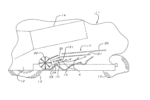
Fig. 1 is a side sectional view of`a combine, showing
the interior thereof with an air deflector panel of one
embodiment of the invention mounted therein;
Fig. 2 is a top view of an air fan and sieve Rection of
a combine and wherein the air defiector panel the embodiment
of the invention shown in Figure 1 has been installed;
Fiy. 3 is a perspective view of the same embodiment of
the invention illustrating its mounted position within the
combine;
Fig. 4 is a view similar to Figure i, but showing
~0 another embodiment of the invention;
Fiy. 5 i5 a top view, like Figure 2, showing the
embodiment of the invention of Figure 4;
Fig. ~ is a side view which is enlarged relative to
Figure 4 to more clearly indicate the position of the air
defiector panel of the invention in relation to the cleaning
farl and the sieves of the combine;
Fig. 7 is an enlarged front view of the embodiment of
1 8
Figure 4, and
Fig. 8 is a still further enlarged ~ide view of the
embodiment of Fig. 4.
In the drawings, reference character~ are uYed to show
S like elements referred to in the description. In Figures i
to 3, the flow deflector panel of the present invention i~
shown as 10 mounted in a combine 11 of the type of models
Case IH SerieY 1440\~0\~0 or Series 1~40\~0\30 which include
a hou~ing 12 carried on ground engaging wheels 13. Within an
upper part of the housing there is provided an axial flow
separating and threshing apparatus 14. Located at the bottom
of the housing is a floor or bottom wall 15 on which the
grain is collected and carried away by augers (not shown).
The grain and some debris, which includes chaff and straw,
falls from the apparatus 14 and is deposited on a sieve means
i7, which includes an upper sieve 20 and a lower sieve ~1.
The two sieve~ are disposed substantially parallel to each
other and ~lant upwardly slightly towards the rear. The
sieve~ 20 and 21 are agitated by drive means (not shown) so
~0 as to a~sist in the grain pa~sing through the sieves to be
collected on the bottom wall 15. A separating cleaning fan
22 iY provided in front of the sieve means i~ and has a
length in the axial direction thereof extending across the
width of the housing. The air which is forced out through
the throat 23 of the fan 2~ i~ directed up towards the front
end of the Yieves 80 that as it fiows through the sieve it
lifts the lighter debris and blows it towards the straw
~41 ,,
~l4~
outlet at the back-oE the housing i2, thus bringing about the
xeparation of the chaff and straw from the grain.
As previou~ly indicated, when combines of these types
are used for combining corn, the separation is very
effective. However, with cereal grains, the separation i8
frequently not complete, and this has been found to be due to
the phenomenon of this type of machine, and particularly of
the type and shape of the throat of the separating fan to
direct a high percentage of the output air toward the front
part of the sieves, thus not fully removing the debris which
collects towards the rear ends of the sieve. Although the
quantity of air fiow from the throat can be adjusted to
provide a higher flow, this causes grain to be ejected from
the sieve~ with the debris while complete debris removal from
i5 the grain is not achieved.
A characteristic of such models of combines which are in
use is that the wall which defines the bottom of the throat
rises at a rather abrupt angle towards the sieves. It may be
noted that this upwardly slanted bottom wall terminates at a
high point or transverse ridge 24 which defineY the outlet of
the throat 23. The ridge 24 of the outlet extends acro~s the
width of the separation chamber. It has been found that
there i~ a tendency, as indicated above, for the air being
expelled past the ridge 24 at the throat outlet to be forced
up through the front part of the sieves and thus not pass
through the ~ieves more towards the rear where a significant
amount of debri~ collects.
1~
~a~
The air deflecting panel 10 of the embodiment of Figures
i to 3 include~ a plate member 30 which extends across the
housing in the path of flow of air from the throat ~3. The
plate 30 has mounting brackets 3;, which are vertical plate
members, attached to opposite ends for affixirlg the air
deflecting panel within the housing. The plate member 30 has
a front portion 3~ which slopes slightly upwardly in a
rearwardly direction and a rear portion 33 formed integrally
with the front portion and sloping upwardly at a greater
angle toward the rear than the front portion 3~. Thus, in
the direction of flow of the air rearwardly from the throat
outlet the plate 30 has a front edge 34 from which the front
portion 3~ extends rearwardly and slightly upwardly to a bend
line 3~ where the front portion 32 integrally joins the front
i5 edge of the rear portion 33, the rear portion 33 then
extending upwardiy at a steeper angle to a rear edge 3~ (Fig.
3). As shown the front portion 32 has a greater width
between the front edge 34 and the bend line 3~ than the rear
portion 33 which extends between the bend line 35 and the
~0 rear edge 3~. The preferred positioning, size and angular
disposition o~ the plate 30 for providing the required air
flow will be deYcribed in more detail below. When installed,
the plate causes the air being expelled from the throat 23 of
the cieaning fan 22 to follow the path denoted by the arrow~
A 90 that a significant portion of the air flow also passes
up through the sieves towards the rear.
As can best be seen in Fig. 3, the mounting brackets are
~ l4~al~
steel plate members which are disposed in parallel vertical
planes so that the outside surface thereof engages the inside
surfaceQ of the side walls of the housing. The air deflector
panel 10 i~ thus provided as an insert in an existing combine
structure, and in the models described, it can be easily
instailed without any modification to the existing structure.
Openings 3~ are provided in the mounting brackets 31 in a
position which allows rem~val of existing bolts 38 in the
combine structure so that they can be inserted through the
openings and the nuts reapplied to fasten the air deflector
panel 10 in its proper location.
Turning now to the embodiment shown in Figures 4 to ~,
the air deflector panel lOa is substantially the same as that
described above except tha-t it is provided with a mounting
means speci~ically designed for mounting in Case IH combines
models which have been sold under Series 1~44\~6\83. The
plate 30 of this embodiment and its placement relative to the
ridge 24 at the outlet of the throat 23 is in fact the same
as that of the earlier embodiment. ~ue to structurai
~0 differences within these model~, however, the mounting means
has been modified so that it can be uYed as an insert without
any modifications to the combine. It may be noted that it
does not include end mounting brackets such as those shown at
31,31 of the earlier embodiment.
2~ The air deflector panel lOa is mounted on a pair of
mounting brackets 40 which are secured to the bottom wall o
top of the transverse ridge 24 at the outlet of the throat
A
.~
~ 14~
23. Each bracket-40 includes a pair of spacer or support
plates 41 which are parallel and vertically disposed in a
plane extending in the direction of the flow of the air from
the outlet of the throat ~3 so as to provide YubYtantially no
resistance to the air passing towards the Yieve means ~0. As
best seen in Figure 8 the plates are YubYtantially of
triangular shape having a top edge 4~ which i8 affixed to the
bottom surface of the front portion 3~ of the plate 30. As
in the earlier embodiment, the plate 30 extends the full
width of the separation chamber and is located between the
outlet of the throat ~3 and the front ends of the sieves 21
and ~. The rear edge 36 of the plate 30 is spaced below and
slightly rearward of the forwardmost edge of the lower sieve
~1, with the forward or front edge 34 of the plate 30 being
spaced above and slightly forward of the ridge 24. The two
pairs of support plates 41 forming part of the mounting
brackets 40 support the plate 30 in such a po~ition. Lower
edge~ 43 of each pair of plates 41 are affixed to an
attachment member 44 which in cross section has a pair of leg
portions 45, 46 so as to form an angular configuration to fit
over the ridge 24 of the models concerned. As shown, the
angle V between the legs 45 and 46 is approximately 110 to
fit over the ridge, and when mounted, the angle W relative to
the horizontal line 14 is approximately 37 . The plates 4;
~5 are 80 configured that their top edges 42 are at an angle
sloping upwardly towardY the rear at an angle X which is
approximately ~ relative to the horizontal ~ine H'. The
f
A
attachment members 4~ have openings ~7 provided in the leg
portions 45 thereof positioned so as to enable attachment to
the ridge ~4 by bolts 48 which are within the existing
structure of the models of the combine for which a deflector
panel lOa i9 designed. Thus, again the installation of the
air deflector panel as an insert re~uires no modification of
the combine.
As is apparent from the above, the front portion 32 of
the plate 30 slants upward away from its front edge 34 at an
i~ angle of about $~ degrees, and this is a preferred angle for
both embodiments. However, as represented by the alternative
po~itionY shown in Figure ~, satisfactory results have been
found over a range where X' is from about 0 to about
The obtuse an~le Y formed between the front portion 3~ and
the rear portion 33 of the plate 30 i8 preferable about 110
which means that for the preferred angle value of about 16
for the front portion 32 relative to the horizon, the rear
portion i8 sloped upwardly and rearwardly at an angle of
about 36 relative to the horizon.
A~ indicated above the front edge of the piate 30 is
spaced above the top of the ridge ~, this vertical distance
being approximately 3 1/~ inches extending up from the ridge,
and this edge is disposed about 1/~ inch forward of the
vertical piane containing the ridges. Tne front portion 3~,
~5 between its front edge 3~ and the bend line 35 has a length
of about 7 inches, and this is the portion which is
preferably disposed at an angle ~ sloping upwardiy and
g
rearwardly toward~ the sieve means 20 at an angle of about
16 . The length o~ the rear portion 33 from the bend line 35
to the rear edge 3~, which is preferably disposed at an angle
sloping rearwardly and upwardly of about 3~ , is about 3
inches.
When installed in the axial flow combines of the above
types, the air deflector panel of this invention results in
the appropriate amount of air being directed, as indicated by
the arrows A, under the sieve mean~ ~0 ~o that it pa~eY
upwardly through the ~ieveY throughout their length in the
rearward direction, thus more effectively removing the chaff
and straw to provide a clean flow of grain onto the bottom
wall 15, while preventing the need for a higher f;ow of air
which could otherwise result in a loss of the grain with the
1~ debri~ being discharged.
While two embodiments of the invention have been shown,
modifications within the spirit of the invention as defined
in the appending claims will be apparent to tho~e ~killed in
the art.
~G
..~.'