Language selection

Search

Patent 2142234 Summary

Third-party information liability

Some of the information on this Web page has been provided by external sources. The Government of Canada is not responsible for the accuracy, reliability or currency of the information supplied by external sources. Users wishing to rely upon this information should consult directly with the source of the information. Content provided by external sources is not subject to official languages, privacy and accessibility requirements.

Claims and Abstract availability

Any discrepancies in the text and image of the Claims and Abstract are due to differing posting times. Text of the Claims and Abstract are posted:

  • At the time the application is open to public inspection;
  • At the time of issue of the patent (grant).
(12) Patent: (11) CA 2142234
(54) English Title: CENTER INTERSECT
(54) French Title: RACCORD POUR PROFILES
Status: Term Expired - Post Grant Beyond Limit
Bibliographic Data
(51) International Patent Classification (IPC):
  • E06B 03/663 (2006.01)
  • E06B 03/667 (2006.01)
(72) Inventors :
  • RASKE, DENNIS J. (United States of America)
  • SEEGER, ROBERT (United States of America)
(73) Owners :
  • DENNIS J. RASKE
  • ROBERT SEEGER
(71) Applicants :
  • DENNIS J. RASKE (United States of America)
  • ROBERT SEEGER (United States of America)
(74) Agent: NORTON ROSE FULBRIGHT CANADA LLP/S.E.N.C.R.L., S.R.L.
(74) Associate agent:
(45) Issued: 2005-08-30
(22) Filed Date: 1995-02-10
(41) Open to Public Inspection: 1995-08-13
Examination requested: 2002-01-11
Availability of licence: N/A
Dedicated to the Public: N/A
(25) Language of filing: English

Patent Cooperation Treaty (PCT): No

(30) Application Priority Data:
Application No. Country/Territory Date
94026499 (United Kingdom) 1994-02-12

Abstracts

English Abstract

An intersect for joining hollow profiles having a molded plastic body which comprises a base and a plurality of tongues extending therefrom, each tongue having at least one upstanding longitudinal extending rib and a transverse bar extending therefrom in the vicinity of said base. The intersect also has a cap which is adapted to be secured to said molded plastic body over said base. The cap shall comprise a front wall and a plurality of abutment walls pending therefrom, with each abutment wall having at least one notch therein.


French Abstract

Un raccord permettant de relier des profilés creux, muni d'un corps en plastique moulé, et comprenant une base et une pluralité de langues s'étendant depuis celle-ci, chaque langue ayant au moins une nervure verticale s'étendant de manière longitudinale et une barre transversale à proximité de ladite base. Le raccord possède également un capuchon pouvant être fixé audit corps en plastique moulé sur ladite base. Le capuchon comporte une paroi frontale et une pluralité des parois de soutien, chacune des parois de soutien étant dotée d'au moins un cran.

Claims

Note: Claims are shown in the official language in which they were submitted.

-7-
CLAIMS:
1. An intersect for joining hollow profiles, comprising:
a center key having a molded plastic body, said center key comprising a base
and
a plurality of tongues extending therefrom, each of said tongues having at
least
one upstanding, longitudinally extending rib and a transverse bar extending
thereacross in the vicinity of said base; and
a cap having a molded plastic body adapted to be secured to said center key
over
said base, said cap comprising a front wall and a plurality of abutment walls
depending therefrom;
wherein each one of said abutment walls has at least one notch therein, said
notch
being sized and configured to mate with said at least one rib of a
corresponding
one of said tongues; and
wherein each one of said abutment walls depends from said front wall such that
each of said abutment walls will be disposed interiorly of said transverse bar
of a
corresponding one of said tongues when said cap is secured to said center key.
2. The intersect as recited in claim 1, wherein each of said abutment walls
depends from said front wall at a location generally inset from the edge of
said
front wall.
3. The intersect as recited in claim 1 or 2, wherein said cap is adapted to be
secured by a snap-fit to said center key.
4. The intersect as recited in claim 1 or 2, wherein said cap is adapted to be
secured by an ultrasonic weld to said center key.
5. The intersect as recited in claim 1 or 2, wherein said cap is adapted to be
secured by glue to said center key.
6. An intersect for joining hollow profiles, comprising:
a center key having a molded plastic body, said center key comprising a

-8-
substantially square base and four tongues extending one from each side of
said
base, each of said tongues having a pair of upstanding, longitudinally
extending
rib and a transverse bar extending thereacross in the vicinity of said base;
and
a cap having a molded plastic body adapted to be secured to said center key
over
said base, said cap comprising a front wall and four abutment walls depending
from said front wall at a location generally inset from the edge of said front
wall;
wherein each one of said abutment walls has a pair of notches therein, said
notch
being sized and configured to mate with said pair of ribs of a corresponding
one
of said tongues; and
wherein each one of said abutment walls depends from said front wall such that
each of said abutment walls will be disposed interiorly of said transverse bar
of a
corresponding one of said tongues when said cap is secured to said center key.

Description

Note: Descriptions are shown in the official language in which they were submitted.


- 1 -
CENTER INTERSECT
Field Of The Invention
This invention relates to an intersect for
joining hollow profiles, such as spacer framer
segments, in the formation of a decorative grille
which can be inserted in a glass or glazing panel
to simulate traditional Georgian windows. The
subject intersect comprises a unitary base which
includes a body portion and a number of tongues
which project from the body portion. These
tongues are to be inserted into the open ends of
various spacer frame segments or other hollow
profiles. The base of the intersect also
includes abutment means providing a positive stop
for abutment with cut ends of the lengths of
frame segment or other hollow profile. The
intersect further includes two caps which may be
welded, snapped or otherwise affixed to the base.
These caps make up for errors in the "cutting" of
the hollow profiles. Such an intersect is often
called a center key in the double glazing
industry.
Background
In most intersects or center keys known in
the art, the body portion of the intersect
remains visible in the finished glazing unit and
is designed to provide a matching, aesthetically
attractive, square-edged interface between the
cut ends of the profiles or spacer frame
segments. Injection moldings are widely used in
the industry to form a one-piece component
incorporating both the attachment tongues and the

- 2 -
center or base section. The polymer used is a
light, ultra-violet ("UV"), stable grade of
pigmented engineering plastic. The mass of the
center base section can cause so-called weld
lines to appear, and can produce shrinkage at the
edges which causes the molded center or base to
gap apart from the raw-cut edges of the profiles
or spacer frame segments.
An alternative form of center key which
currently appears in the marketplace has the body
portion made up of metal covers which are held in
place by integral tongues which project into the
ends of the profiles or spacer frame segments.
This system enables the covers to be paint
finished, matching exactly the finish of the
profiles or spacer frame segments. However, this
known arrangement still has several
disadvantages, which include the following:
1. ) The cut ends of the profiles or
spacer frame segments remain exposed, detracting
from the visual appearance of the finished
grille.
2.) The range of metal cap configurations
which can be produced is very limited due to
metal forming techniques.
3.) The metal caps can clatter against
the glass due to vibrations, caused by, among
other things, traffic or airplanes.
An aim of the present invention is to
overcome the limitations of currently known
integrally molded intersects or center keys and
center composite keys or intersects with metal
covers.

~~~~2~4
- 3 -
Summary Of The Invention
The present invention proposes a profile
center key or intersect, which is provided with a
molded plastic cap to cover the base portion of
the intersect. The caps have a lip or flange
portion which, in use, overlies the cut end of a
length of profile or spacer frame segment when
such profile or segment is brought into contact
with the abutment means.
The abutment means may be formed on the
main part of the center key or intersect, but is
preferably formed on the cap. The position of
the cut end of the profile or spacer frame
segment is therefore determined relative to the
cap rather than the base portion of the
intersect, ensuring that the end of the profile
or spacer frame segment is covered irrespective
of the relative positions of the cap and base
portion of the intersect.
The cap is preferably secured to the main
part of the center key or intersect by snap
engagement therewith, although it may also be
secured to the base o the intersect by use of an
adhesive or by sonic welding. In most cases, two
such caps will be provided on opposite sides of
the base portion of the intersect.
The advantages of the present center key
or intersect overcome the limitations of
currently known center key or intersect designs
and can be summarized as follows:
1. The cut ends of the profiles are not
visible.
2. Only one main unitary base needs to
be molded for a given size of profile.

2~~22~4
- 4 -
3. The main unitary base can be molded
in inexpensive materials without regard to color
in order to reduce component costs.
4. The molding tools for the caps can
easily be provided with interchangeable inserts
for manufacture of various cover shapes.
5. The caps can be molded from different
colored materials for use with a range of profile
or spacer frame segment colors at minimum cost.
6. The caps can be cycled quicker,
reducing molding costs.
7. Shrinkage problems related to molding
of heavy sections are eliminated.
The invention will be described in more
detail below in connection with the drawings.
Brief Description Of The Drawinas
The following description and the
accompanying drawings referred to therein are
included by way of example in order to illustrate
how the invention may be put into practice. In
the drawings:
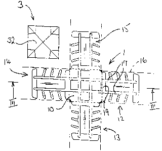
Figure 1 is a plan view of the unitary
base of a center key or intersection according to
the invention together with a cap which is shown
separately.
Figure 2 is an end view of one of the
unitary bases shown in Fig. 1 with two caps in
place, above and below the unitary base.
Figure 3 is longitudinal section taken
through the unitary base of Fig. 2.

212234
- 5 -
Detailed Description Of The Drawings
Referring to Fig. 1, the unitary body
portion 1 of the center key or intersect is an
integral plastic molding which includes a
substantially square base part 10 having four
tongues 12-15 of known form projecting from its
four sides to receive four profile or spacer
frame segment sections 16, shown in outline only.
The tongues each have a pair of upstanding
10 longitudinally extending ribs 17 which are
continued across the base part 10 to be
continuous with the ribs 17 for the opposite
tongue_ At the root of each tongue the ribs 17
are bridged by a transverse bar 19.
The opposite rear face of the unitary body
portion 1 is of substantially the same
configuration, and a pair of substantially
identical caps 3 are provided to completely cover
and enclose the opposite faces of the base part
20 10 (only one being seen in Fig. 1). The front
wall 32 of the cap is substantially square and
may be of any desired style (e. g., "square cut"
or "pyramid") to provide an aesthetically
attractive interface between the profiles or
spacer bar segments 16.
As can be seen in Fig. 2, an abutment wall
33 depends from each of the four straight edges
of the front wall 32, being slightly inset from
the extreme marginal edge of the front wall 32
30 which thus forms a projecting lip 38. The four
abutment walls 33 are each provided with double
notches 34 to receive the ribs 17 when the cap is
superimposed on the base portion 10, in which

2L~~~3~
- 6 -
position the abutment walls 33 are positively
located between the four transverse bars 19.
The two caps 3 may be secured to the base
portion 10 by means of a suitable adhesive, by a
suitable plastics welding technique such as sonic
welding, or by means of cooperating snap-
engageable formations on the cap and base
portion.
When a length of profile 16 is pushed over
one of the tongues 12 as shown in Fig. 3, the
leading cut end of the profile or spacer bar
segment eventually abuts the wall 33 which
provides a positive stop for the profile or
spacer bar segment, hiding the cut end from view.
Although the lip is short, its length is still
sufficient to cover the end face of the profile
or spacer bar segment in the event of normal
shrinkage in the length of the profile or spacer
bar segment.
The caps and base portion can be formed
with an aperture for insertion of a resilient
glass buffer, to prevent clattering against the
glass sheets in a double glazing panel.

Representative Drawing
A single figure which represents the drawing illustrating the invention.
Administrative Status

2024-08-01:As part of the Next Generation Patents (NGP) transition, the Canadian Patents Database (CPD) now contains a more detailed Event History, which replicates the Event Log of our new back-office solution.

Please note that "Inactive:" events refers to events no longer in use in our new back-office solution.

For a clearer understanding of the status of the application/patent presented on this page, the site Disclaimer , as well as the definitions for Patent , Event History , Maintenance Fee  and Payment History  should be consulted.

Event History

Description Date
Inactive: Expired (new Act pat) 2015-02-10
Inactive: IPC from MCD 2006-03-11
Grant by Issuance 2005-08-30
Inactive: Cover page published 2005-08-29
Pre-grant 2005-06-13
Inactive: Final fee received 2005-06-13
Letter Sent 2005-04-06
Notice of Allowance is Issued 2005-04-06
Inactive: Approved for allowance (AFA) 2005-03-21
Amendment Received - Voluntary Amendment 2004-09-20
Inactive: S.30(2) Rules - Examiner requisition 2004-03-25
Inactive: S.29 Rules - Examiner requisition 2004-03-25
Inactive: Status info is complete as of Log entry date 2002-03-22
Inactive: Application prosecuted on TS as of Log entry date 2002-03-22
Letter Sent 2002-02-08
Request for Examination Received 2002-01-11
Request for Examination Requirements Determined Compliant 2002-01-11
All Requirements for Examination Determined Compliant 2002-01-11
Letter Sent 1999-04-07
Reinstatement Requirements Deemed Compliant for All Abandonment Reasons 1999-03-31
Deemed Abandoned - Failure to Respond to Maintenance Fee Notice 1999-02-10
Application Published (Open to Public Inspection) 1995-08-13

Abandonment History

Abandonment Date Reason Reinstatement Date
1999-02-10

Maintenance Fee

The last payment was received on 2005-02-09

Note : If the full payment has not been received on or before the date indicated, a further fee may be required which may be one of the following

  • the reinstatement fee;
  • the late payment fee; or
  • additional fee to reverse deemed expiry.

Patent fees are adjusted on the 1st of January every year. The amounts above are the current amounts if received by December 31 of the current year.
Please refer to the CIPO Patent Fees web page to see all current fee amounts.

Owners on Record

Note: Records showing the ownership history in alphabetical order.

Current Owners on Record
DENNIS J. RASKE
ROBERT SEEGER
Past Owners on Record
None
Past Owners that do not appear in the "Owners on Record" listing will appear in other documentation within the application.
Documents

To view selected files, please enter reCAPTCHA code :


To view images, click a link in the Document Description column. To download the documents, select one or more checkboxes in the first column and then click the "Download Selected in PDF format (Zip Archive)" or the "Download Selected as Single PDF" button.

List of published and non-published patent-specific documents on the CPD .

If you have any difficulty accessing content, you can call the Client Service Centre at 1-866-997-1936 or send them an e-mail at CIPO Client Service Centre.


Document
Description 
Date
(yyyy-mm-dd) 
Number of pages   Size of Image (KB) 
Representative drawing 1998-03-12 1 15
Description 1995-02-09 6 203
Abstract 1995-02-09 1 16
Drawings 1995-02-09 1 31
Claims 1995-02-09 2 68
Claims 2004-09-19 2 59
Representative drawing 2005-03-20 1 10
Courtesy - Abandonment Letter (Maintenance Fee) 1999-03-09 1 187
Notice of Reinstatement 1999-04-06 1 172
Reminder - Request for Examination 2001-10-10 1 129
Acknowledgement of Request for Examination 2002-02-07 1 178
Commissioner's Notice - Application Found Allowable 2005-04-05 1 162
Correspondence 1995-09-12 1 17
Fees 1999-03-30 1 36
Correspondence 2005-06-12 1 30
Fees 1997-01-21 1 58