Note: Descriptions are shown in the official language in which they were submitted.
~I~:2307
0 94/04461 PC.'1"/'US93/07654
1
METHODS AN AP AR.AT OR ODUCING F
This invention relates to improved methods to synthe-
size the new form of carbon referred to as fullerene, Buck-
minsterfullerene and Huckyballs and to novel apparatus
'suitable for carrying out such methods.
83~ORGROUI~D OF THE INOEH'f ION .
Huffman, Rr~tschmer et al. Natu e, vol. 347, No. 6291,
pg. 354-358, 27 September 1990, disclosed a process for
synthesizing Cfi0 and C~0 which consists of vaporizing small
graphite rods via resistance heating ~r arcing in a non
oxidizing atmosphere of helium at a preferred pressure of
100 tort. The process is excellent for producing fuller
enes. The soot yield from a graphite rod is generally up
to about 60% and the soot contains up to about 10% fuller-
enes. Attempts to scale up this process via using larger .
graphite rods, for example greater than ; to ~ inch diam-
stet, result in lower yields of soot and fullerenes. High
power vaporization of the graphite rods reduces yields.
The most convenient way to vaporize the graphite rods is a
controlled arc between the rods. Automation of graphite
rod feeding with a controlled arc to produce large quanti-
ties of fullerenes is difficult due to alignment of the
small rods for arcing, and automation of supplying a new
WO 94/04461 2 ~ ~ ~ 3 ~ .~ PCT/U593/07~
2
graphite rods after the rods have bean burned in the 100 -
200 torr helium environment is also difficult. Graphite
rods are also an expensive source of carbon.
OBJECTS AND ADVANTA(;ES OI° PRESENT INDENTION
It is an object of the present invention to overcome
the scale-up difficulties of the Huffman/Kr~itschmer graph-
ite rod vaporization process, as well as provide an im-
proved method for synthesizing fullerenes and to provide
apparatus suitable for practicing such methods. These and
other objectives are achieved in accordance with one aspect
of the instant invention by use of a form of carbon that
can be poured or fed to the place of vaporization as a flu-
id in a stream or flow of particles or powder or as a liq-
uid or gas comprising in whole or in part carbon which is
vaporized and condensed to produce fullerenes. A preferred
embodiment of the invention involves the use of carbon par-
ticulates which may be in a stationary bed when vaporized
or which may be continuously fed as a fluid stream of par-
ticles to the reaction zone where it is heated and vapor-
ized. As contrasted to graphite rods, carbon particulate
can readily be continuously fed into a non-oxidizing atmos-
phere at 100 - 200 torn or other pressures that were dis-
covered in accordance with the instant invention which cov- ,
er the range of 10'6 torr to 760 torr.
It is a further object of this invention to provide
improved methods and means for vaporizing carbon in the
production of fullerenes. These techniques are particular-
--°"O 94/04451 PCI"/US93/07654 _.
21423x7
3
1y useful to vaporize carbon powder or particulate as it is
supplied continuously to a reaction zone where the heat is
applied. Advantageously, the heat is supplied by appropri-
ate means for producing an arc, plasma, electron beam, ion
beam, laser beam or the like for causing solid particulate
carbon to vaporize.
It is also among the objects of this invention to pro-
vide improved methods and apparatus for producing fuller-
enes wherein the source of carbon comprises a hydrocarbon
that may be in a gas, liquid or solid form and which may
also comprise the quenching medium when in the fo~:m of a
gas or liquid.
SUMMARY OF '1°HE IN~ENTIt~h1
7Cn accordance with the present invention, a fluid form
that may be. carbon particulates or a form of hydrocarbon in
a liquid or gaseous state or as a particulate are continu-
ously fed to the vaporization zone or reaction zone sup-
plied with heat from the source in an atmosphere and under
other conditions that cause the vaporized carbon to form
fullerene structures which includes C6o, COQ and carbon
forms of higher molecular weight having the structural con-
figuration of fullerenes. The fullerene structure can be
that known in the art which consists of hexagons and penta-
goes to form closed structures as well as tubular shapes.
One embodiment of the instant invention is a process
of producing fullerenes by vaporizing particulate forms of
WO 94J04461 y
PCT/US931076~~,
4
carbon in an environmental condition that forms fullerenes,
as well as apparatus to carry out this process.
The instant invention utilizes a variety of heat or
power generating sources that are effective to vaporize
large quantities of carbon on a continuous basis . To over
come the limitations of precision feeding graphite rods on
a continuous basis and the limitation for scaling to large
size such as greater than ~ inch diameter rods, a preferred
embodiment of the instant invention utilizes means to feed
particulate carbon continuously as a fluid stream of par-
titles to an intense heat generating source, such as an
arc, electron beam, plasma that include electrodeless type
sources such as induction, microwave, sputtering and la-
sers. The heat generating systems are preferably config-
i5 ured to maximize the heat in a unit area to which carbon
particulate is continuously fed and vaporized under con-
ditions that maximize the formation of fullerenes. The
gases utilized in the heat or plasma systems are non-oxi-
dizing such as the noble gases including helium and argon,
and may be a reactive gas such as hydrocarbon preferably
with a low hydrogen to carbon ratio. In certain embodi-
ments, the hydrocarbon in either liquid or gaseous form may
serve as both the source of carbon for the fullerenes and
as the quenching medium. The processing conditions that .
surround the carbon particulate during vaporization axe
those that are known to stimulate the formation of fuller-
enes such as an atmosphere of 100-200 torn, as known in the
cited article published by Huffman, et. al., as well as
-.~,y0 94/04:161 2 ,~ ~~ 3 0'~ ' ~~reus93eo~s5a
broader range in accordance with embodiments of the present
invention which extend from about 10''b torn to 76o torr.
Also employed are controlled quenching conditions which
stimulate the formation of fullerenes such as temperature
5 controlled condensation surfaces created by additional
heating or cooling that include baffles, shrouds, etc.,
which are utilized to maximize the formation of fullerenes
of various molecular weights and structures.
Any source of particulate carbon which includes graph-
ite, amorphous, glassy, carbon black, soot, reclaj.med car-
bon or even the fullerene form, is vaporized by am appro-
priate energy source in conjunction with condensation con-
ditions to form fullerene molecular structures that include
tubular shapes. convenient and economical heat sources
suitable to vaporize particulate carbon are electric arc,
plasma, microwaves, lasers, electron beam and sputtering,
-which may also be loosely described as plasma or ion beam
vaporization. The carbon can also be vaporized through
combustion and the combustion-vaporized carbon can be con
densed as fullerenes. Descriptions of preferred embodi
ments of apparati and techniques for vaporizing carbon in
the form of particulates and other forms that are quenched
or condensed into fullerenes follow.
In accordance with certain embodiments wherein the va-
porized carbon is produced from hydrocarbons, whether in
liquid, gaseous or particulate form, the fullerene synthe-
sis process may be carried out by pyrolyzing, cracking or
combusting the hydrocarbon to provide the carbon atoms that
WO 94/044tr1 ~ s , A °~. PCT/US93/076~?'~,
', !:--' ., ' ~ ,. r , . ~,;;~.'
6
are vaporized and condensed to form fullerenes. Thus, the
carbon atoms may be derived from the 'hydrocarbons through
breakdown of hydrocarbons in the gaseous liquid or solid
phase using an appropriate source of heat, as described
hereinafter.
DHSCRIPTION OF THE g=Gmt~R
Figure 1 is a schematic representation of apparatus
according to the present invention wherein particulate car
bon is continuously fed to a reaction zone heated by an arc
system.
Figure 2 is a schematic representation of apparatus
similar to that shown in Figure 1, but wherein the arc sys-
tem is replaced by an arc plasma system for heating the
reaction zone and wherein the particulate carbon is fed to
a reaction zone down-stream of the electrodes.
Figure 3 is a schematic representation of another form
of the arc system shown in Figure 2, wherein the carbon
particulate is fed directly through the electrodes to pro-
vide more efficient heating to vaporize the carbon.
Figure 4 is a schematic representative of a further
embodiment of the invention wherein the electrode system
for heating the carbon is immersed in a liquid, such as
benzene, that is suitable for quenching the vaporized car- ,
z5 bon and for solubilizing fullerenes.
Figure 5 is a schematic representation of another form
of the system of Figure 1 wherein the heating source com-
prises an arc type heat generation system.
< < . ., ,, . . r , ..~ . :..
PCT/US93/07654
~-' ~O 94/04461 . . ',r, . E ~ : ,
21
Figure 6 is a schematic representation of another form
of the system of Figure 1 wherein the~heating source com-
prises an induction plasma type system.
Figure 7 is a schematic representation of another form
of the system of Figure 1 wherein the heating source cam-
prises a sputtering system.
Figure 8 is a schematic representation of another form
of the system of Figure 1 wherein the heating source com-
prises a laser system.
Figure 9 is a schematic representation of another form
of the system of Figure 1 wherein the heating source com-
prises an electron beam system.
Figure 10 is a schematic representation of another
form of the system of Figure 6 wherein the heating source
comprises a microwave source to induce plasma.
Figures ila and lib are a schematic representations of
other forms of the system of Figure 1 wherein hydrocarbon
is used as the source of carbon to produce fullerenes and
the heating source comprises electric resistance elements.
Figure 12 is a schematic representation of another
form of the system of Figure 1 wherein the source of carbon
can be carbon particulate or a hydrocarbon or a combination
thereof and the heat of vaporization is provided by a flat
plate burner.
Figures 13a and 13b are schematic representations of
systems modeled after those of Figures 1 and 3 and which
are directed to the use of hydrocarbons as the carbon
source.
WO 94/U4461 PCT/U593/f17~'°=a
~. E.. r. .. S .
8
Figure 14 is a schematic representation of a system
for using hydrocarbons as the carbon source and which is
modeled after the system of Figure 10.
Figure 15 is a schematic representation of a system
zor using hydrocarbon as the carbon source and which is
modeled after the system of Figure 6.
Figure 16 is a schematic representation of a system
generally like that of Figure 1 but which provideas means
for continuously passing a bed of carbon particulate
through an arc generated between the electrodes.
Figures 17a and b show the visible-ultraviolet ab-
sorption spectrum of collected soot showing the presence of
fullerenes as described in examples of the invention.
Figure 18 shows the mass spectrograph of collected
soot showing the presence of primarily C6Q as described in
example 21.
DESCRIPTION OF PREFERRED EMBODIMENTS
Arc ~apolrizatioa
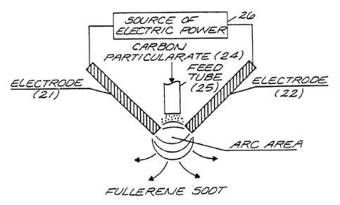
Figure 1 shows one arc-type configuration that util-
izes carbon particulates to synthesize fullerenes and
wherein the carbon particulate may be continuously fed by
a feed tube 5 to the reaction zone where an arc is pro- ,
duced. A pair of spaced electrodes 1 and 2 are connected
to a suitable source of electric power 6 to generate an arc
between them for heating the carbon particulates 4 in a
reaction zone within the reactor 3 to provide vaporization
'°~~ 'O 94/04461 ~ P~1'/US93/07654
2142307 1
of the carbon. The electrodes 1 and 2 are disposed within
a reactor 3 comprising a container f armed of metal or other
t
material effective to contain the quenching gas at the req-
uisite atmospheric pressure. An arc between electrode 1,
which is in the form of a rod, and the other electrode 2,
which comprises a container for the particulate carbon 4 to
be vaporized . The container 3 may comprise a graphite
crucible for holding the carbon particulate 4 near the tip
of the electrode rod 1 provides the most efficient ,trapori-
zation. The composition of the rod forming electrode 1 can
be graphite or any refractory material that will conduct
electric current such as refractory metals of tungsten, mo-
lybdenum, tantalum and other alloys or ceramics such as
carbides, borides, nitrides, oxides, etc. The electrical
power applied between the electrodes 1 and 2 can be stan-
dard alternating current, direct current, high frequency
current with various wave configurations, alternating cur-
rent superimposed on direct current and any power type may
be pulsed. In the case of direct current if the particu-
late carbon comprising electrode 2 is the anode, higher
burning rates of the carbon is achieved.
Although not, essential for the production of fuller-
enes, in accordance with a preferred aspect of the inven-
tion the helium or non-oxidizing quenching gas is fed di-
rectly into the vaporization area, as shown, thereby pro-
viding a convenient and effective way to transport the pro-
duced carbon soot away from the vaporization area, as well
as providing the quenching to improve the efficiency of
fullerene formation.
WO 94/~4451 2 ~ ~ 2 3 I~ ,~ '., ~ . ' ~, PCT/US93/076x'''1,
14
In accordance with other forms -of the invention, the
quenching gas may be introduced in the chamber comprising
the reactor 3, through a passageway (not shown) that may be
provided in electrode one through feed tube 5 or fed just
generally in container 3. The gas can be helium, argon or '
any noble gas, or a hydrocarbon which can be pyrolyzed to
enhance carbon soot formation and the production of fuller-
enes. If a hydrocarbon is utilized, the lower the hydrogen
to carbon ratio the better with respect to hydrogen inter-
feting with cage closure in the formation of fullerenes.
Examples of low hydrogen/carbon ratio compounds are acety-
lens, benzene, naphthalene, anthracene, naphthacene, etc.
The atmospheric conditions in container 3 are those
effective to enhance the formation of fullerenes such as
10'6 - 760 tort of an inert quenching gas such as a noble
gas, helium being used in a preferred embodiment. In a
further embodiment the quenching gas may be a hydrocarbon
as described above. Steep temperature gradient fixtures in
the reactor, can be an asset to enhance fullerene formation
such as water cooled chimneys, shrouds, covers, etc., may
also be utilized in chamber 3 to enhance the yield of ful-
lerenes through condensation of the vaporized carbon. Baf-
fles that are not water cooled such as graphite shrouds can
also enhance the yield of fullerenes.
Advantageously, means are provided for cooling the re-
gion surrounding the reaction zone in the chamber 3 to en-
hance quenching of the vaporized carbon and its condensa-
tion and the collection of fullerenes. This may be done by
..,. ' , . , ..
' ' g'CT/U593107654
'~ ~ WO 94/04461
2I4z~p'~
11 6
the use of an appropriate heat exchanger such as water
cooled copper coils surrounding the electrodes 1 and 2.
Figure 2 depicts a system generally like that of Fig-
ure 1, but wherein the heat generating system disposed
within the reactor 3 of Figure 1, comprises an arc plasma
system utilizing technology similar to that used for power
i
spray of coatings. xn the system shown in Figure 2, carbon
particulates 14 of select size that can be vaporized in the .
arc are fed to an arc produced between a pair of spaced
electrodes, 11 and 12, that are connected to a source of
electric power 16, similar to the power source 6 of Figure
1. The first electrode 11 is shown as a tapered rod dis-
posed within and spaced from a surrounding tube 17, whereby
the annular space 18 surrounding the rod electrode 11 pro-
vides a conduit for the flow of inert quenching gas past
the electrode to the arc at the reaction zone between rod
electrode 11 and the second electrode 12 shown as a plate
having a generally circular aperture opposite the tip of
rod the electrode 1l. The carbon particulates 14 fed to
the arc produced between electrodes 11 and 12 are vapor-
ized and quenched to form fullerenes. As with fullerenes
produced in the system of Figure 1, the quenched fullerenes
are condensed on the inner walls of the container 3. Any
particulate that is not vaporized or that condenses as non-
fullerenes is recycled. The actual configuration of the
arc is not critical, except that is must operate to vapor-
ize the carbon particulates. Arcs that utilize tubular
shapes, double helix flow patterns, high enthalpy configu-
2~~230~
WO 94104461 y ~ Pt.'T/US93/0?G5-,
12
rations are excellent for vaporizing the carbon particu-
late.
The gas utilized in the arc process can be a noble gas
such as helium, argon, xenon, or any non-oxidizing gas
which can also include hydrocarbons such as listed in the
description of Figure 1. The hydrocarbons may be added
with the inert gas or exclusive of the inert gas.
. The chamber 3 surrounding the arc plasma should be
closed to prevent oxidizing conditions, and to facilitate
the generation of pressures and quenching conditions to
produce fullerenes. In addition to the inner walls of
chamber 3, collector devices, cooled plates, baffles,
shrouds, etc., may also be used to enhance condensation of
the vaporized carbon in the chamber 3 to enhance fullerene
formation.
In Figure 2 the carbon particulate 14 is fed through
first and second feed tubes 15, 16 to the vaporization zone
or reaction zone down-stream of the electrodes 11, 12,~
which is similar to the procedure used in a typical arc
plasma powder spray system. In some cases to provide addi-
tional heat to vaporize the carbon particulates, it is de-
sirable, to feed the particulates such that they pass
through the arc of the electrodes. Figure 3 shows such a
system in which the carbon particulate is fed through the
electrodes within the chamber 3 of Figure 1, to achieve
maximum heating to vaporize the carbon particulates. In
the system of Figure 3, the arc is produced between first
and second spaced electrodes shown as rods 21 and 22 dis-
".7 94/04461 ~ PCf/US93/07654
I~~307
. _:
posed at oblique angles. The electrodes 21, 22, can be
i
graphite or the same materials listed for the rod-type
electrode 1 shown in Figure 1. The carbon particulate 24
r
is fed through a feed tube 2 5 , and f lows by gravity or car-
tied by a feed gas such as helium, argon, or a hydrocarbon
into the reaction zone produced by an arc between the tips
of the spaced electrodes 21 and 22 caused by the applica-
tion of electric power from the source 26 connected to the
electrodes 21 and 22. The quenching gases including hydro- :,
carbon for the arc, the collection of soot and containment
to establish conditions to stimulate fullerene formation,
is the same as described in Figure 1, The source of elec-
tric power may be as described for the source 6 of Figure
1.
Another embodiment of the invention is shown in Figure
4. Unlike the system shown in Figure 3, wherein the atmos-
phere surrounding the arc comprises a quenching gas under
pressure that is known to form fullerenes, e.g. 10-6 - 760
tort and preferably 100 - 200 tort, in the embodiment shown
in Figure 4 the electrodes system comprises first and sec-
and spaced electrodes 31, 32, surrounded by a liquid 33
such as a hydrocarbon that is open to atmospheric pressure.
Example liquids may be those that are known to solubilize
fullerenes such as benzene, toluene, 1,3,4,5 tetramethyl-
benzene, methylnaphthalene, etc., In the embodiment shown
in Figure 4, the liquid 33 is contained by a container 35
comprising a reactor that may be open to the atmosphere as
shown. The carbon particulates 34 are maintained stationary
WO 9/04461
PCT/US93/07
~'~'',
2142307
14
in the liquid 33 between the electrodes, 31,32, as for ex-
ample, by means of a screen 37 in the bottom of the con-
tainer 35 such as a glass beaker. Arcs produced between
the electrodes 31, 32 and between the carbon particles 34
in a stationary position are best produced with pulsed pow-
er from electric power source 36 that generates sparks be-
tween particles 34 to vaporize the particles 34 at the
point of the arc, which comgrises the reaction zone. Move-
ment of the particles 34 , such as by vibration, .generates
multiple arc points and consumes the particles 34. The va-
porized particles are quenched in the surrounding liquid 33
and fullerenes are immediately soluble in the hydrocarbon
liquid 33. The liquid will heat due to the arcing process
and to prevent vaporization of the liquid, it must be heat
exchanged as by means of the cooling soils 38 through which
coolant is continuously circulated from an external cooling
system 39 that may be of conventional design. The arcing
under the liquid process can be operated with carbon parti-
cles 34 between the electrodes 31, 32 and continuously fed
from a source of carbon particulate as with the apparatus
of Figure 1, or without, in which case electrodes 31,32 are
directly arced.
In the liquid-quench system of Figure 4, the vaporiza
tion of the carbon and quenching thereof take place at at
mosphere pressure rather than at the pressure range de
scribed for operation of the systems of Figure 1, 2 and 3.
Figure 5 depicts an arc type heat source which is re-
ferred to as a transferred arc. It is similar to the sys-
rWO 94/04461 PC~'/US93/07654
~j~~30~
,w , ~ , . .
15 w .
tem shown in Figure 1 but the rod type electrode 1 of Fig-
ure 1 is replaced in Figure 5 with the arc type heat gen-
eration system wherein a f first electrode shown as a tapered
rod 41 surrounded by a f first and second tubular members 4 2 ,
43, the inner tubular member 42 being spaced from the ta-
pared rod 41 to form a first annulus 45 through which,
quench gas, such as argon, is fed from a source to the
reaction zone at the tip of the rod type electrode 41. The
ffirst or inner tubular member 42, in turn, is surrounded by
a second annulus 4 6 produced by the space between the inner
and outer spaced tubular members 42, 43 through which car-
bon particulate 44 is fed to the reaction zone opposite the
tip of the rod electrode 41. The reaction zone is defined
by an arc between the tip of rod electrode 41 and a second
electrode shown as a flat plate 47 situated in a plane gen-
erally perpendicular to the axis of the rod electrode 41 .
and having a round aperture 48 directly opposite and spaced
from the tip of the rod electrode 41. The carbon particu
late 44 is fed through the outer annulus 46 to the arc
where it is vaporized. Advantageously, the inner and outer
tubular members 42, 43 are also tapered toward the tip of
the rod electrode in order to direct the carbon particulate
44 and the quench gas, which may also contain hydrocarbons,
more effectively toward the center of the arc. Both the
rod electrode 41 and the plate electrode 47 may be formed
of solid carbon material or other suitable electrode ma-
terials as described for the electrodes of Figure 1 and 2.
WO 94/04461 . ~. v PCT/US93/076~'~''-.
2142307
16
In the system of Figure 5, the-vaporized carbon pro-
duced in the reaction zone will, for~~the most part, pass
through the aperture 48 in the plate electrode 47 and the
fullerene soot comprising the quenched carbon product will
condense and collect upAn the walls of the container or
reactor 3 (as in Figure 1) or upon such other condensation
and collection surfaces as may be included within the re-
actor 3 that encloses the reaction zone.
The gases in the arc system, quenching and collection
systems, and conditions in the atmospheric controlled sys-
tams of Figure 5 are similar to those described concerning
the systems of Figures 1, 2 and 3. Likewise, the electrode
materials for both or either of electrodes 41 and 45 may be
the same as discussed above for electrode 1 of Figure 1.
In accordance with a further embodiment of the inven-
tion utilizing an arc type heat source, the plate electrode
(anode) 47 may be a solid block of carbon which will be
consumed and provide the source of carbon to be vaporized
to produce fullerenes in lieu of the source of particulate
carbon 44.
Figure 6 depicts an induction plasma type heat source
to which carbon particulate is fed and vaporized by the in-
duction produced plasma. Of course, a solid carbon rod may
be fed into the induction plasma and vaporized. The in-
duction plasma is generated in the reactor by known means
such as an appropriate radio frequency generator that oper-
ates at I~z or I~giz frequencies. In Figure 6, the reactor
51 is shown made of quartz to afford an appropriate closed
~'~ ~ WO 94/044b1 ~ ~ ~ ~ ~ ~ ~ . PCT/U~93/07654
17 ' ~ ' '
container for confining the quenching gas in the heated
reaction zone induced by the radio f~ssquency energy pro-
duced by the induction coil 52 coupled to the radio fre-
quency power source 56. The plasma gases, the container 51
providing the closure, the atmosphere and collection of
fullerenes are function essentially the same as those of
Figures 1, 2 and 3, as described above. The plasma gases
may be the same as the quench gases described for the em-
bodiments of Figures 1, 2 and 3 and may include added hy-
drocarbons as described and listed in regard to the systems
of Figures l, 2 and 3.
Tnstead of an induction produced plasma to vaporize
the carbon particulates, as shown in Figure 6, a microwave
produced plasma can be utilized to vaporize the carbon par-
ticulates. Figure 10 shows a microwave system for vapor-
izing carbon particulate 104 which is fed into a quartz re-
actor 103 inta which the requisite quenching gas is also
maintained at the effective pressure to provide the condi-
tions for fullerene production when plasma is produced in
a reaction zone in the reactor chamber 103 by subjecting it
to microwave energy from an appropriate generator coupled
to a waveguide.to direct the microwaves through the quartz
walls into the reactor. The microwave plasma is a special
case of the MHz plasma at the specific frequency of 2450
MHz. Lower and higher frequencies can be utilized to gen-
erate the plasma to vaporize the carbon particulates or to
couple directly to the carbon particulates which may be
sized in relation to the frequency of the applied microwave
._..;,. .. :;. :. .. y , . ' . .
WO 94104461 Pf.'T/US93/076.
;-, -- - ;, ;. , ;. .
,n.'~~.t
18
source to create more efficient coupling and thus greater
efficiency of heating and vaporizing the particulates. A
solid carbon rod, or plate or the like can also be vapor-
ized by the induction, microwave or higher frequency power
generation systems. As in the other cases, the plasma or
working gases including hydrocarbons, the devices to quench
and collect the fullerenes and the container conditions to
generate fullerenes are the same as those described in Fig-
ure 1 and 5.
l0 Figure 7 depicts yet another system for vaporizing
carbon particulates or solid carbon to produce fullerenes.
zt is a sputtering system in which carbon particles or sol-
id carbon is the cathode 61 in a magnetron type sputtering
system. The working gas within the reactor 3 is a noble
gas, hydrocarbon or non-oxidizing gas in which ionization
occurs and wherein a magnetic field generated by the magne-
trop is applied to accelerate the ionized gas causing it to
collide with the carbon surface and vaporize carbon atoms
that are then quenched to form fullerenes. The sputtering
system may be powered by a standard direct current (DC)
magnetron type depicted in Figure 7, rf type which may
operate over a wide range of frequencies, electron beam
. type, ion beam or laser type which also can be operated at
a wide range of frequencies. The reaction zone is enclosed
in a suitable container comprising a reaction for contain
ing the reaction zone, the atmosphere conditions for the
quench gas and the condensation and collection surfaees for
the fullerenes.
~''''O 94/04461 . PCT/U593/07b54
2142307
19
In the system of Figure 7, the sputtering gases may
comprise noble gases and may include hydrocarbons, as de-
scribed for Figure 1. likewise, the collection devices and
pressure are the same as described in Figure 1.
Figure 8 depicts apparatus generally like that of Fig-
ure 1 wherein electrode one of Figure 1 is replaced with a
laser source 72 that vaporizes the carbon particulates 74.
The laser source 72 shown in Figure 8 can be known types
such as GO2, YAG, Exmier, etc. As with the system shown in
Figure 6 a laser can be used to vaporize particulates pass-
ing through a containment system comprising the reactor 3.
In the system of Figure 8, there is shown a container
73, comprising a reactor for containing the quenching gas
under the atmospheric conditions described for the system
shown in Figure 1, and which is preferably maintained at
the pressures described below for laser systems such as
laser 72 which is positioned to produce a laser beam 75
that is directed by a mirror 75, through a window 76, in
the container 73, to impinge upon a source of carbon 74 in
the reaction zone. The laser beam 75 vaporizes the carbon
74, which may be in the form of a rod or plate or in the
form of particles and augmented by a totally hydrocarbon
source fed into the reactor, thereby producing vaporized
carbon that is quenched as fullerenes, collected on the
inner walls of the reactor or other condensation surfaces
-~ therein and separated as in the system of Figure 1.
Figure 9 depicts another embodiment of, the invention
similar to Figure 1 or Figure 8, wherein the electrode sys-
WO 94104461 . ,. ~, , ,: F'CT/US93/07~~
l' '' w ~ 'x'14 2 ~'~
tem of Figure Z or the laser of Figure 8 is replaced with
an electron beam source which will vaporize the carbon par'
ticulates and in the Figure 1 or 9 arrangements can also
vaporize the carbon particulates.
Tn the system of Figure 9, there is shown a reactor
vessel or container 83 to which a pair of electron beam
generators 81 and 82 are mounted for directional electron
beams to a reaction zone 85 shown in the center of the re-
actor 83 and above which is shown in a dispenser 86 for
10 feeding carbon particulate 84 to the region compri:aing the
reaction zone 85 where the electron beams from the two
sources 81 and 82 converge and impinge upon carbon particu-
late 84 introduced or fed to the reaction zone 85, thereby
vaporizing the carbon, which is then s~uenched, condensed
15 and separated as with the systems of Figures 1 and 7.
Of course, solid carbon in the form of rods, plates,
blocks, etc., or hydrocarbon gases, liquids or solids, can
be substituted for carbon particulate 84 in the system of
Figure ~. The electron beam source may be a single source
20 or several sources to vaporize the carbon. Contrary to the
100 - 200 torr pressure reported by the Huffman et. al. ,
when using carbon rods in an arcing system.to vaporize car-
bon, the use of a sputtering system or electron beam system '
to vaporize the carbon permits operation at much lower
pressures, in the range of 10-3 - 10-6 torn, with attendant
advantages.
To overcome the expense of graphite rods as a source
of fullerenes and the scale-up difficulties, hydrocarbons
~'~~ 94/04461 i 4 :; ,I ~ ~ ~'~ PCT/US93/07654 .
.. p ~ '
z1 ~
are a near ideal carbon source to synthesize fullerenes.
The hydrogen from the hydrocarbons can interfere with the ~
symmetrical closure to form fullerenes and thus should be
minimized as much as possible. Accordingly, hydrocarbons
with as low a hydrogen/carbon ratio as possible should be
used as the precursor to synthesize fullerenes.
The methods of pyrolyzing, cracking or generating car-
ben atoms in the gas phase to condense and form fullerenes
include plasma, combustion and thermal pyrolysis. The con-
ditions of the hydrocarbon breakdown region are set to max-
imize the formation of fullerenes which are generally known
to be an atmosphere of quench gas at 100-200 torr, but in
accordance with the present invention, it has been deter
mined that pressures of 10-6 torn to above one torr and
several atmospheres can also nucleate fullerenes.
In accordance with preferred embodiments of the pres-
ent invention, a hydrocarbon is continuously fed to the
carbon generation region, 1.e., the reaction zone of the
reactor, which provides the economics of continuous opera-
tions and can be scaled into large operations as contrasted
to prior art graphite rod processes.
Operating conditions of feeding hydrocarbons to a
heating source or reaction zone to produce fullerene soot
can be varied to produce only select fullerene molecular
strengths and structures, such as only Cso, or other large
molecular weight fullerenes, or tubular shapes.
The embodiments of the instant invention for convert-
ing hydrocarbons to fullerenes utilizes techniques of in-
W~ 94104461 , . . PCT/US93/07~".""";
_.
22
tensely heating the hydrocarbon under conditions which
favors the formation of fullerenes. The instant invention
provides a variety of techniques for heating the hydrocar- .
boos to cause vaporization of carbon clusters and condense-
tion to form fullerenes. The heating techniques include
any form of arcs, and especially high enthalpy arcs includ-
ing passing the hydrocarbon through the arc, electroless
plasmas that includes induction types and microwave, ther-
mal processing that includes passing the hydrocarbon over
heated surfaces' or through beams that cause the hydrocarbon
to be intensely heated such as electron beam or laser, and
combustion that includes multiconfiguration burners that
may also be a sheathed double burner or burner within a
burner.
The pyrolytic condition of the hydrocarbons consist of
those known to favor fullerene formation which is prefer-
ably 100-200 tort but also includes 10-~ tort up to several
atmospheres. The environment of condensing the pyrolyzed
hydrocarbon into fullerenes can consist of quenching pro-
files, that may include heated or cooled surfaces that fa-
vor fullerene structure formation.
The hydrocarbon precursor can be any gas, liquid or
solid feed to the heating system. Since hydrogen can in-
terfere with fullerene ring closure a low hydrogen/carbon
ratio is preferred, Hydrocarbons which have low hydrogen/-
carbon ratios include acetylene, benzene, naphthalene, an-
thracene, naphthacene, polynuclear aromatics (e. g. Coron-
,' 'r~WO 94/04461 ~~~~ PC'a'/US93/07b54
2 3 ' : v t'
ene) etc. , which form excellent sources to transform to the
fullerene structure.
There are a number of arc configurations which can be
used to provade the thermal energy that will pyrolyze hy-
drocarbons under conditions for the formation of fuller-
eves. The arc types include direct arcs between two elec-
trodes, one electrode and a tube, parallel plates, etc. In
any electrode configuration and especially those that pro-
vide high enthalpy, the gas is non-oxidizing such as a no-
ble gas or entirely the hydrocarbon. Figures 13a and 13b
show electrode systems particularly suited to produce ful-
lerenes through the use of carbon derived from hydrocarbons
subjected to an electric arc in an appropriate reactor.
The system of Figure 13a comprises a reactor 103 for
containing the hydrocarbons in an appropriate environment
to provide for vaporization of carbon and quenching of the
vaporized carbon products to provide fullerenes as de-
scribed herein. First and second rod shaped electrodes
101x, 102a, which may be similar to electrodes 21 and 22 of
Figure 3, are disposed at an oblique angle to one another
with a space between their tip ends where an arc is pro-
duced by the application of electric power from a source
106a, which may be similar to the source 6 of Figure 1 or
the source 26 of Figure 3. suitable hydrocarbon, as de-
scribed herein, is fed from hydrocarbon source 105a through
hydrocarbon feed tube 107a to the reaction zone defined by
the are between the tips of the electrodes lOla, 102a where
the arc causes the carbon~from the hydrocarbon to be vapor-
WO 94/04461 ~ PGT/US93/0765,,
,2~~~3t~7
~! :.~ f
_. . 24
ized. The vaporized carbon is quenched by the surrounding
inert gas atmosphere and condensed and collected within the
reactor 103 as with the systems of Figures 1 and 3.
Figure 13b shows another form of electrode system for
the system of Figure 13a, wherein the solid rod shaped
electrodes 101a and 102a are replaced by hollow rod elec-
trodes lOlb and 102b and wherein hydrocarbons from the
source of hydrocarbons 105b is fed through an axial bore
through the center of each of the electrodes lOlb, 102b, to
the reaction zone, rather than through a separate feed tube
as in Figure 13a.
This modification allows greater feeding in the manner
of disposing the electrodes 101b, 102b, which are shown ax-
Tally aligned opposite one another, rather than angled as
in Figure 13a.
In the case where a gas in addition to the hydrocarbon
is used, the hydrocarbon is blended with the non-oxidizing
gas and passed through the arc or at least close to the
arc, to provide sufficient heat to pyrolyze the hydrocar-
bona. The operating conditions of the arc system are such
that the carbon produced from pyrolysis of the hydrocarbon
maximizes formation of the fullerene structure. This typ-
ically is a pressure of 100-200 tort but may cover the
range of about 10'6 tort up to several atmospheres.
Arc systems that are typically known as plasma arcs
including high enthalpy arc designs, generally do not pass
any gas or solid through the electrodes that may react,
which in this case is the hydrocarbon. Even if the elec-
f~~; ~'O 94/061 PCT/US93/07654
v ~''' ~~~~2307 .
trodes are carbides or materials that may be resistant to
carbon, the pyrolyzed hydrocarbon can°deposit on the elec-
trodes and alter the electrical operation of the arc. For
these reasons, the hydrocarbon would typically be added in
5 the downstream flow of the electrodes. Tn many cases this
is satisfactory to transforming hydrocarbon into fuller-
eves. However, far cases where it is desirable for the
hydrocarbon to pass through the arc, graphite electrades
are recommended and if these electrodes vaporize they too
10 can form fullerenes similar to the Huffman/Kr~tschmer pro
cess. An example of this electrode arc system is shown in
Figures 13a and 13b. The power source for the electrodes
can be direct current or alternating current of any fre
quency which is the case in any of the arc systems to py
15 rolyze hydrocarbon and transform to fullerenes.
As shown in Figures ~, 8, 9, 10 and 14, for example,
there are a variety of techniques to generate a plasma that
do not involve two electrodes. High frequency power is
discharged into a cavity which ionizes the gas and gener-
20 ates a plasma. An example of such a system especially fit-
ted to accept a hydrocarbon gas is shown in Figure 14. The
system of Figure 14 is essentially like that of Figure 10,
except that the input comprises an appropriate hydrocarbon,
rather than carbon particulate and quenching gas as shown
25 in Figure 10. In both Figure ZO and Figure 14, the reac-
tion zone of the system is in a closed container for main-
taining atmospheric conditions for quenching the vaporized
carbon and collecting the fullerenes as in Figure 1. The
WO 94/04461 r i_ ''r : . F,CT/US93/0'7~''..""'1
214237 26
frequency of power can be in the range of KHz to MHz. Well
known frequencies used to generate plasma are 476 KHz, 3-a5
l~iz and X450 MHz which is microwave. In the latter case a
wave guide is generally utilized to transmit the power as
contrasted to inductive power coils. However, no matter
what the frequency, a plasma is generated without or with
a noble gas and the hydrocarbon is transformed into fuller-
eves. The operating conditions are adjusted to favor the
quenching of the carbon into the fullerene structure which
is preferably 100-200 torr but can be in the range of 10"6
torr up to several atmospheres.
A laser can also be used with the system shown in Fig-
ure 8 to pyrolyze the hydrocarbon to generate fullerenes.
In such cases, the system of Figure 8 is modified to pro-
vide for inputting the hydrocarbon, rather than helium or
non-oxidizing quenching gas and the graphite source may be
omitted. In any event, the system is closed, as with the
system of Figures 10 and 14 , to provide the quenching of
the vaporized carbon, and collection of the fullerenes as
in the Figure 1 system.
Figure 15 shows a system essentially like that of Fig-
ure 6 wherein the input is a hydrocarbon feed, rather than
a carbon particulate feed.
Hydrocarbons may be pyrolyzed by conventional thermal
processes that begin as low as just above red heat and can
be as high as there are materials that can be heated to
transfer the heat to the hydrocarbon. Examples of pyrolyz-
ing hydrocarbons are to produce pyrolytic graphite or high-
<:..-,w0 94/04461 ~ ~ 4 ~ 3 ~ ~ PCI'/US93/(~7654
2.7~'. ' .',
1y oriented pyrolytic graphite (HCPG).particulates. If the
pyrolytic conditions axe set at the conditions that favor '
i
condensation of the fullerene structure, then hydrocarbon ;
pyrolysis will produce fullerenes. Examples of suitable ,
reactors are shown in Figures lla and 11b, wherein means
are provided to pass the hydrocarbon through a heated tube
150 or over a heated surface 151 with the surrounding con-
ditions in the closed reactor 203 adjusted such that the
hydrocarbon pyrolysis is transformed into the fullerene
structure. The materials of the tube 150 or heating sur-
face 151 can be those that are easily resistant heated much
as the silicides (MoSi2), carbides (SiC, TaC, etc.), the
refractory metals such as tungsten or graphite. The closed
system 203 contains an appropriate atmosphere for quenching
the vaporized carbon, condensing and collecting the fuller-
ene, like that of Figure 1.
The heating technique for the system shown in Figure
11 can be an electron beam instead of the resistance heated
surface. Such a heating system is illustrated in Figure 9.
In the case of a hydrocarbon source for carbon, the carbon
particulate feed is replaced by a source of hydrocarbons as
shown in Figures 13a and 13b. The hydrocarbon passing
through an electron beam will be heated and pyrolyzed to
transform into fullerenes. A laser beam may also be util-
ized to pyrolyze the hydrocarbon as discussed above. The
pyrolyzed hydrocarbon can be quenched into controlled tem-
perature prof files and onto controlled temperatures surf aces
WO 94/04461 PCT/U593/076.~ ~.
~1'423-U?
28
(heated or cooled) to provide the required conditions to
form fullerenes.
The hydrocarbons can be transformed into fullerenes by
combustion. It is well known that to burn hydrocarbons
with oxygen will produce what is known as a sooty flame,
i.e., one that produces uncombusted carbon. The oxygen to
carbon ratio can be adjusted to produce a saoty flame and
if the surrounding conditions are adjusted to those known
to favor fullerene formation, then combustion can be used
to produce fullerenes. To favor the temperature profile
that forms fullerenes, a shrouded or sheathed burner can be
utilized with the sheath a non-oxidizing gas or a burner.
An example of a burner of this type is shown in Figure 12.
The sheath burner can be operated with the same fuel or
hydrocarbon as the inner burner or different hydrocarbon,
or can be supplied with a different oxygen to fuel ratio.
The sheath can also be a non-oxidizing gas. Also, such a
gas can be injected into the flame to create quenching con-
ditions to favor fullerenes formation. The burner shown in
Figure 12 is referred to as a flat plate burner, but many
configuration burners can be used to burn hydrocarbons to
produce fullerenes. For example, the burners may be as
shown in Figure. l2, the flat plate burner 180 is supplied
with fuel form fuel source 181, . oxidizer source 182, and
diluent 183 via a fuel supply system of a type known in the
art of flat plate burners to produce an appropriate combus-
tion at the burner 180. The fuel may be any hydrocarbon,
but it is preferably a hydrocarbon having a hydrogen-to-
. , .,
v . v , ; : :. ,
i
2 ~14 2 3.0 7 PCT/LJS93/U76s4 s
~'~'::-.'O 94/04461
2g ~ 1
carbon ratio of one (1) or less, since a higher percentage
1
of hydrogen in the hydrocarbon increases the likelihood s
1
that the hydrogen will interfere with the cage closure of
the fullerenes. Examples of suitable hydrocarbons are
acetylene, benzene, toluene, naphthalene and the like.
Advantageously, a. two stage fuel preparation system
may be used to strip hydrogen (dehydrogenate) the hydro-
carbon fuel before passing it into the burner in the reac-
tion zone. For example, hydrocarbon fuel comprising natur-
al gas is passed over a pyrolizer such as that shown in
Figure 11 where it is heated to strip off the hydrogen
which is diverted from the fuel stream before it is fed
into the burner 180 of Figure 12. The oxlctlzer gay ~c ~l~
or oxygen. The diluent, if any, may be helium, argon or any
noble gas, which may be the inert gas comprising the quench
gas.
The carbon particulate or hydrocarbon particulate, or
a combination thereof , may be ink ected under pressure to
the flame front in the flat plate burner.
The container comprising the reaction enclosing the
burner and reaction zone of the Figure 12 system must be
suitable to contain the quench gas in an atmosphere such as
that of Figure 1 wherein the vaporized carbon is quenched
for condensation and collection on appropriate surfaces as
in the system of Figure 1.
combination M~thods
Fullerenes may preferentially be formed by using a
combination of heating methods that may include combustion
f:'0 94/044b1 PCT/U~93/07~"''~,
.; ; :...
.. :,230'
as one method. Since the hydrocarbons contain at least
some hydrogen, the combination method~anay use a first step
that would primarily strip the hydrogen and a second step
that transforms the hydrocarbon into fullerenes. The cam-
5 bination method could include an arc system plus combus-
tion, arc system plus electroless system, an electrodeless
system such as microwave or induction plus combustion, etc.
The system shown in Figure 16 is a modified version of
the system shown in Figure 1 and which is designed to pro-
10 dace fullerenes at a relatively high volume. The Figure 16
system employs an electric arc to vaporize carbon particu-
late in an atmosphere like that of Figure 1, wherein a
suitable quenching medium is confined within a reactor,
wherein the electric arc vaporizes the carbon to produce
15 fullerenes that are collected from the quenched carbon va-
por. In Figure 16 the electrode system comprises a gener-
ally disc shaped graphite electrode 500 having an outer rim
rising above its outer edge to prevent carbon particulate
from being thrown off its upper surface by centrifugal
20 force when the disc is rotated below a rod shaped graphite
electrode 504 positioned above and generally perpendicular
to the flat surface of the disc 500. Carbon particulate is
fed to the top of the disc 500 as it is rotated by means of
a suitable electric motor or the like (not shown). An
25 electric power source 505, such as the power source 6 of
Figure 1, is coupled to the electrodes 500, 504 to produce
an electric arc between the tip of the rod 504 and carbon
particulate on the surface of the disc electrode 500 caus-
''~=':fJ 94104461 PCT/US93/07654 _
.. _;2.~.~230~
31
ing the particulate to vaporize in the reactor where it is
quenched, condensed and collected as fullerene soot as with
the system of Figure 1. A smoothing blade, known as a Doc-
for blade 503 is mounted above the surface of the disc 500
to smooth the surface of the carbon particles 501 deposited
thereon, thereby maintaining a substantially uniform thick-
ness in the layer of particles as the disc rotates and the
particles pass through the arc between the disc 500 and the
tip of the rod 504.
30 The system of Figure 16 is described further in the
description of example 15 infra.
WO 94/04461 PC:T/US93107~""":
.:
:,,
. . y' '~
3z
Example 1
Using a system as illustrated in Figure 1, carbon par-
ticulates as calcined petroleum coke in the size range of
40 to 6250 microns was put into container 3 which was a
graphite crucible two inches in diameter. Electrode 1 was
a graphite rod one inch in diameter and was connected as
the cathode to a do power supply. System comprising chain-
ber 3 was pumped to 10-a torr, backfilled with argon, re-
pumped to 10-3 torr and backfilled to'200 torr with helium.
An arc was created by lowering electrode 1 to touch carbon
particles 4 supported in the crucible 2 and then raised
whence the arc was maintained at 20 volts and a current of
125 amps. The carbon particles 4 were consumed as the an-
ode and carbon soot was generated. The soot condensed on
the walls of the vacuum chamber 3. After thirty minutes of
operation the arc was stopped by raising electrode 1 and
turning off the power. The soot on the wall was collected
and shown to have 10% solubility in toluene which is char-
acteristic of fullerenes.
Examination of electrode 1, the cathode, revealed that
a solid deposit of carbon had formed around the edges of
the electrode. This solid deposit of carbon was easily
broken from the edges of the electrode and it was noted
some pieces of such carbon had fallen off electrode 1 and
was laying on tap of the particle bed 4. This solid deposit
of carbon was examined utilizing a transmission electron
microscope and found to contain a tubular shape of fuller-
enes.
"'WO 94104461 PC~/U593107654
:, ,.~I4230
33
Example 2
The carbon garticulates of example 1 was in the size
range of 1000 to 10,000 microns and the power was 60 cycle
alternating current. Surrounding container 2 and electrode
1 Was a water cooled heat exchanger made from ; inch copper
tube. Carbon particulate 4 was put into the particulate
feed tube 5. The experiment was run at a higher power of
30V and 175 amps. As the carbon particulate was consumed,
additional particulate fell into container 2 from feed tube
5. After two hours operation, the generated soot was col
lected from the heat exchanger surfaces and the vacuum
chamber walls. The soot fraction that dissolved in toluene
was 8.5% indicating fullerenes by the characteristic cor
dova to near black color after filtering out the undis
l5 solved soot.
Example 3
Example 1 was repeated with heat exchanger from Ex-
ample 2 but using argon as the residual gas instead of
helium. The fullerene yield in the soot was 5%.
Example 4
Example 3 was repeated but the residual gas was
acetylene and the fullerene yield was 3.8%.
Example 5
Example 3 was repeated with the residual helium
pressure at 500 torr and the fullerene yield was 7.6%.
Example 6
Carbon particulate which was reclaimed automobile tire
carbon black was fed into an arc plasma as shown in Figure
WO 94/04451 . . PCT/US93/076~v.
..
34
2 using helium as the working gas. The discharge of the
jet was in chamber 3 of example 1 to prevent any oxidation
of the va prized carbon , '
p particulate. Chamber 3 was main- ~
twined at a pressure of 15o tart. The vaporized carbon
_ ,
soot was collected from the walls of chamber 3 and found to
contain 8% toluene soluble fullerenes.
Example 7
Cabot Utility Grade Elack Pearls 130 carbon particu-
late was utilized and fed into an arc configuration ;shown
in Figure 3 utilizing helium working gas with chamber 3
operating at ?60 tort in a residual atmosphere of mixed
helium and argon. Three heat exchanger types were utilized
to collect the soot in chamber 3. The circular water
cooled copper tubing of example 2 was utilized closest to
the arc discharge. Downstream of the circular heat ex-
changer a water cooled flat plate was utilized and main-
twined at a angle of approximately 45° to the perpendicular
of the arc issuing from the electrode. In a similar but
opposite plane, an uncooled graphite plate was utilized to
collect soot. After operating the arc for Z hour, soot was
collected from all three heat exchanger surfaces and the
walls of chamber 3. The circular heat exchanger soot con-
tained 3% fullerenes, the flat plate 5% fullerenes, the
graphite plate 6% and the chamber walls 4.5% fullerenes. .
Example 8
Example 6 was repeated with the heat exchangers of ex-
ample 7 with the graphite replaced with grafoil and the
copper cooled heat exchangers lined with grafoil. Chamber
. v~ 94/04461 ~ ~ ~ ~ PGT/US93/07654
i~ Y o .
3 was maintained at 50 torn pressure with a residual gas of
argon. The feed or working gas with the carbon particulate
was acetylene. The carbon particulate was the insoluble
soot from other fullerene runs. The soot collected in this
5 experiment demonstrated an average fullerene content of 6%
as measured by toluene solubility.
Example 9
A four liter glass beaker was filled with toluene in
a system as depicted in Figure 4. Two one inch graphite '
10 electrodes were inserted with 1000 to 5000 micron carbon
particulate filled 2 inch deep between the electrodes. An
ac welding power supply was attached to the graphite elec-
trodes with a power of 35V. The current was 80 amps with
values in the 50 to 120 amp range. Multiple arc points
15 could be seen between carbon particulates. Within a few
seconds the solution began to turn tan and as time pro-
gressed, the solution turned darker. After a few minutes,
the toluene solution began to boil and the experiment ter-
urinated. The toluene was filtered to separate the carbon
20 particulate and any non-fullerene soot. The remaining
solution contained 3% fullerenes.
Example 10
Experiment 9 was repeated using methylnaphthalene in
the solvent with a pump installed to pass the solvent
25 through a refrigerated heat exchanger. The beaker was set
on a vibrating table and a pulsed power supply was util-
ized. The pulsed rate was l5Hz at a power of 400V and 30
amps. The experiment was run for one hour and the solution
WO 94/04461 PCT/US93/07_
36
filtered to remove the graphite particles and non-fullerene
soot. After evaporation of the methylnaphthalene the ful-
lerene content was 4.20.
Example 11
Petroleum coke carbon particulates in the size range
of 40 - 1000 microns was fed to the plasma region as shown
in Figure 5 with a chamber pressure of 300 torn using a
working gas of 50 helium 50 argon. The petroleum coke par-
ticulate was volatilized in the plasma and soot collected
on the walls of the vacuum chamber. Toluene solubility
showed that the collected soot had 5% fullerenes.
Example 12
The system in Figure 5 was modified such that the an-
ode was a solid block of graphite three inches in diameter.
No carbon particulate were fed into the plasma . The vacuum
chamber was maintained at 200 tort with 50x argon-helium.
The plasma vaporized the anode block and soot was collected
on the walls of the vacuum chamber. The soot contained 7~
toluene soluble fullerenes.
Example 13
A 40K Lapel induction power supply with 476KHz and 3-
8l~iz frequencies was utilized at approximately SMHz. A
four turn coil was wrapped around a two inch diameter water
cooled quartz tube as generally shown in Figure 6. A ven-
Lure powder feed system was utilized to feed carbon black
from reclaimed automobile tires. The pressure was reduced
to one tort with helium which generated a plasma at about
' SKW. The power was increased to about 15KW and carbon
~'7 94!04461 . PCT/US93/07654
v_~~~:::~~1~"1
37
black was fed into the plasma which.was vaporized gener-
sting a soot that was collected on the water cooled walls
of the quartz container. The soot was tested for fullerene
solubility in toluene and found to contain 6% fullerenes.
Example 14
The experiment in example 13 was repeated and the
operating gas helium was passed through benzene which was
passed into the plasma. The flow was adjusted to achieve
an approximate 50150 helium-benzene~mixture in the gas
phase. The pressure was adjusted to be 10 torr and carbon
power feed was begun. The soot collected on the water
cooled quartz walls contained 7% fullerenes.
Example 15
An example of high volume production of fullerenes was
demonstrated utilizing the system shown in Figure 16. A
rotating flat graphite plate 500 is fed with carbon partic-
ulate 501 through feed tube 502. The smoothing blade,
which is known in the art as a doctor blade 503, smoothes
the carbon particulate to pass under electrode 504 which is
the cathode when using a do power supply. Electrode 504
may be any material as desribed in Figures 1, 3 and 13 and
has a slight taper to control the arc distance With the
carbon partiuclate on the flat graphite plate. A do power
supply 505 was utilized with a voltage of 25v and a current
of 175 amps. Graphite plate 500 was slowly rotated at 10
revolutions per hour with carbon particulate fed and con-
sumed at approximately 100 grams per hour. Larger elec-
trodes 504 and graphite plate 500, as well as multiple
~O 94/a4461 ~ ' ' . .' ~. PC.'T/US93/07 .
2142307
38
cathode elctrodes 504, can vaporize more carbon particulate
in unit time. Helium was used as the working gas at a
pressure of 150 tort. Heat exchangers as described in Fig- ,
ures 2, 3 and 4, were used to condense the carbon vapor.
The soot collected off the heat exchangers contained I2%
toluene soluble fullerenes.
Example 16
A quartz tube was utilized in the system shown in Fig-
ure 10. A 5KW microwave system was utilized to generate a
helium plasma in the quartz tube at 1 torn. Carbcm black
was fed with a venturi feed as described in example 13.
The quartz tube was forced air cooled at the extremities of
the plasma. The plasma volatilized the carbon black par-
ticulate and the soot condensed on the cooled quartz tube.
Fullerene content as toluene soluble was 5.5%.
Example 17
Carbon particulate in the size of 1000 - 10,000 micron
was placed in an aluminum container as shown in Figure 7.
The magnets can be permanent or electromagnets which in
this case had a rating of approximately 10 gauss at 55V
and 4 amps. The do sputtering power was run at 500V do and
20 amps at a pressure of 0.01 tort residual helium. A wa-
ter cooled copper plate with a grafoil surface as described
in example 7 was utilized adjacent to the anode-cathode ,
spacing. The experimental run was made for one hour and
the soot collected on the grafoil surface, as well as the
vacuum chamber walls of the sputtering systems. The soot
showed 3% fullerenes by toluene solubility test.
~::~"-.~VO 94/04461 P~:I'/US93/47654
39~. ~ .-
Example 18
Example 16 was repeated using a solid block of graph-
ite and the sputtering gas was 50 helium:50 argon with a
pressure of 0.03 torr. The sputtering power supply was 2ItW
microwave. Soot collected on the grafoil heat exchanger 5
surface and walls of the vacuum chamber showed 3.3% fuller-
i
eves.
Example 19
Two electron beam guns as shown in Figure 9 were util-
10' i2ed in a vacuum of 10"6 torr in vacuum chamber 83. Carbon
particulate with a particle size in the general range of 1
to 40 micron was fed through tube 86 into the electron
beams operating at 14 IZVA. The circular copper, flat plate
copper and graphite slab heat exchanger as described in ex-
ample 7 were utilized around and below the electron beam.
The vacuum chamber was lined with aluminum foil. The ex-
periment was contained for one hour at an electron beam
power of approximately 7KW. The soot collected on the heat
exchangers and aluminum foil liner of the vacuum chamber
contained 4% fullerenes. The extracted fullerenes were
dried onto neutral alumina and placed on top of a neutral
alumina packed chromatographic column one inch in diameter.
Techniques for purification and separation of C60 and C~0
are known in the art and are discussed, for example, in the
PCT patent application of Huffman et al published 19 March
1992 (19.03.92) International Publication Number W092/-
0429. See espECially pages 13, 14. Hexane was used to
f lush the column. by standard chromatographic technique also
WO 94/(34461 , , ; : ~ . PCT1US93/076?'"'~
known for separating C60, C~0 and higher fullerenes. See
also F. Lliederick et al "The Higher Fullerenes: Tsolation
and Characteristics of C~6, Ca4, C9~, C94 and C~oO an Oxide
of D5h- CEO, Science vol. 252, pg. 548. It was noted the
5 ratio (band width of absorbed material in the columns) of
C~0 and higher molecular weight fullerenes was substan-
tially different from that obtained from fullerenes synths-
sized b~T the graphite rod method of Huffman/Kr~tschmer.
The typical ratio of fullerenes in the Huffman/Kratschmer
10 technique is 92C60-4 to 6 C~a and 2 to 4 higher fullerenes.
The fullerenes produced by the electron beam showed approx-
imately 20 C6~ - 50 Cep - 30 higher fullerenes.
Example 20
The system in Figure 2, low hydrogen to carbon ratio
15 hydrocarbons are fed to the reaction zone instead of par-
ticulate carbon. The plasma is started with an inert gas
such as argon and acetylene is added in place of carbon
particulate. The acetylene is cracked producing carbon
soot which is collected as previously described. The soot
20 was dissolved in toluene and found to contain 2% fuller-
eves.
Example 21
Example 20 was repeated using a system in Example 19
in which the plasma gas was helium. The collected soot
25 contained only C60 as shown in the mass spectrograph of
Figure 18.
~'~~='WO 94/04461 PCT/US93I07654 _
2~4~307
4 ~ -. ,.
Example 22
Example 20 was repeated and naphthalene was fed as a
solid similarly to the carbon particulate. The cracked
naphthalene soot was collected as before and found to con-
tain 2.5% soluble fullerenes.
Example 23 ~ w
The system shown in Figure 3 was utilized and benzene
vapor was fed in place of the carbon particulates. The
cracked benzene soot was collected as previously described
and found to contain 3.3% soluble fullerenes.
Example 24
The electrodes in Example 3 were made of graphite
tubes through which a mixture of acetylene and benzene were
fed which was cracked to a soot that had 4.5% soluble ful-
lerenes.
Example 25
The system in Figure 6 was utilized and anthracene was
fed in solid particulate form instead of carbon particulate
and the cracked soot collected as previously described.
The cracked soot contained 4.1% soluble fullerenes.
Example 26
The system shown in Figure 8 was utilized and naphtha
lease granules were fed into the tube in front of the graph
ite backing plate using a Co2 laser which produced a soot
containing 1% soluble fullerenes.
Example 27
The system in Figure 9 was utilized in which naphtha-
lease was fed into the electron beams which were cracked and
WO 94/04461 . PCT/US931076,
.~~ 4 2
produced a soot that contained 5% toluene soluble fuller-
eves.
Example 28
A mixture of acetylene and benzene was fed into the
microwave plasma of helium, shown in Figure 14, which was
cracked and produced a soot containing 3.~% soluble
fullerenes.
Example 29
A system as shown in Figure 11b Was utilized that con-
tained a tungsten filament. The pressure in the system
was adjusted to 150 torr helium and the filament heated to
200°C. Acetylene was passed over the hot filament that
cracked it into soot which contained 2.?% fullerenes.
Example 30
Experiment 28 was repeated with a system as in Figure
11b using natural gas and a carbon filament. The fullerene
contained in the soot was 1%.
Example 31
A burner system as shown in Figure 12 was utilized.
Naphthalene was fed by vaporizing into the flame. The
outer shielding was natural gas and oxygen burned at a
slightly reducing ratio. The naphthalene-oxygen flame was
burned to produce soot or referred to as a sooting flame.
The soot was collected on heat exchangers as described in
Figures 2, 3 and 4 and found to contain 7% soluble fuller-
eves.
~'.~ ~=~!) 94104461 PCT/US93/07654
.4~ , ;2y4230'~
Example 32
Example 30 was repeated and carbon particulate was
used as the fuel to the inner burner with the flame set to
be a sooting flame. The soot was collected and found to
contain 7.5% soluble fullerenes.
Example 33
Example 30 was repeated with the fuel a mixture of
natural gas and carbon particulate and the shielding flame
was omitted with a shield of helium gas. A looting flaming
condition was set in the burner and the soot collected.
The soot contained 4.3% fullerenes.
' Example 34
Example 31 was repeated in which the microwave gen-
erator of Figure 14 was directed across the looting flame
in which the fuel source was methylnaphthalene, the shield-
ing flame was also used. Greater quantities of soot were
produced and the soluble fullerenes were found to be ZO% on
the water cooled heat exchangers.
Example 35
The electrode system in Figure 3 was combined with the
electrodeless induction plasma of Figure 6 and carbon par-
ticulate was fed through electrodes 21 and 22. The working
gas was helium and the pressure in system 3 was 10 torr.
The combined plasma vaporized the carbon particulate which
was collected on heat exchangers as described in Figures 2,
3 and 4. The soot from the heat exchanger contained 12%
soluble fullerenes.
4
x;
WO 94104461 - PCT/US93/07;
Y. _.
Example 36
The experiment of example 35 was repeated with benzene
as the carbon feed source, The helium working gas was ,
passed through liquid benzene and through the electrodes 21
and 22. The collected soot contained 9% soluble fuller-
eves.
The above embodiments and examples are given to illus-
trate the scope and spirit of the instant invention. These
embodiments and examples are within the contemplation of
the present invention. Therefore, the present invention
should be limited only by the appended claims.