Note: Descriptions are shown in the official language in which they were submitted.
21~ 83
PATENT
TAMPON APPLICATOR HAVING A SEMI-SPHERICALLY SHAPED PLEATED TIP
FIELD OF THE INVENTION
This invention relates to a tampon applicator having a
semi-spherically shaped pleated tip for facilitating insertion of a
catamenial tampon into a body cavity.
BACKGROUND OF THE INVENTION
Catamenial tampons and other types of absorptive media are
routinely inserted into body cavities, such as a woman's vagina, to
absorb menstrual fluid, blood and other kinds of body fluid. One
convenient way to position such absorbent tampons into a body cavity
is through the use of an applicator. Comfortable and clean insertion
of the absorbent tampon are keys to repeated sale of such
applicators. In addition, the applicator should be capable of
inserting the absorbent tampon into the body cavity using an
acceptable amount of expulsion force.
Tampon applicators are available in a variety of shapes and
sizes with the two piece telescopically assembled design being the
most prevalent. In the two piece applicator, the tampon is housed in
an outer tube and is expelled into a woman's vagina by an inner
member which is telescopically mounted in the outer tube and acts as
a plunger. Some tampon applicators utilize a hollow tube having an
open insertion end through which the tampon is always exposed while
other applicators utilize a completely closed or partially closed
design. A thin film membrane can cover the insertion end of an
applicator to completely enclose the forward end of a tampon while
folds and pleats can be used to partially enclose the forward end of
21431~83
a tampon and protect it from contamination. Still other applicators,
especially plastic applicators, have a plurality of flexible petals
formed on the forward end of the outer tube which can flex radially
outward to allow the tampon to be expelled. It will be appreciated
that the diameter of the applicator, the material from which it is
formed, the basic configuration of the applicator, the size and shape
of the tampon positioned in the applicator, as well as the ease of
opening the forward end of the applicator will all influence the
force required to expel the tampon therefrom. The expulsion force
should be kept reasonably low to permit proper functioning of the
applicator.
While many have tried to design and manufacture tampon
applicators having these improved qualities, there still remains a
need for a tampon applicator which is more comfortable to use. Those
applicators having an open forward end tend to expose the dry
absorbent fibers of the tampon to the interior walls of a woman's
vagina and this can cause irritation during insertion. Commercially
available plastic applicators, using a plurality of petal tips
separated by slots, can sometimes pinch or cut the vaginal tissue of
a woman during insertion and cause discomfort. Paper applicators
having partially or fully closed tips tend to require an increased
expulsion force to expel the tampon from the applicator and this can
cause the applicator to deform or cause the tampon to be inserted
incorrectly. Such insertion can cause discomfort to the user.
Now a paper tampon applicator has been invented having a
semi-spherically shaped pleated tip for facilitating comfortable
insertion of an absorbent tampon into a woman's vagina while having a
low expulsion force.
SUMMARY OF THE INVENTION
Briefly, this invention relates to a paper tampon applicator
having a semi-spherically shaped pleated tip for facilitating
insertion of a catamenial tampon into a woman's vagina. The tampon
applicator includes a first member capable of housing an absorbent
tampon. The first member has a central longitudinal axis and first
and second ends. An insertion tip is integrally formed on the first
end of the first member and extends outwardly therefrom. The
2143083
~ insertion tip contains a small central aperture which extends
therethrough and the aperture has a side wall which is aligned
essentially parallel to the central longitudinal axis of the first
mèmber. The insertion tip contains a plurality of pleats arranged in
a semi-spherical configuration. The pleats are capable of expanding
radially outward as the tampon is expelled from the first member.
The tampon applicator further includes a second member telescopically
mounted in the second end of the first member. The second member is
adapted to expel the tampon through the insertion tip as it is pushed
into the first member.
The tampon applicator is also disclosed in combination with a
catamenial tampon having a shaped nose which approximates the
interior surface of the first member.
Oneaspect of this invention is to provide a paper
tampon applicator having a semi-spherically shaped pleated tip for
facilitating insertion of a catamenial tampon into a body cavity. A
more specific aspect of this invention is to provide a tampon
applicator having a uniquely formed tip which prevents premature
contamination yet substantially encloses the forward end of an
absorbent tampon.
Another aspect of this invention is to provide a tampon
applicator having a pleated tip which essentially éncloses the
forward end of an absorbent tampon and which can be opened with a
minimum amount of force.
A further aspect of this invention is to provide a paper tampon
applicator which is economical to manufacture and easy to use.
Still another aspect of this invention is to provide a paper
tampon applicator which will minimize discomfort to a woman when she
inserts an absorbent tampon into her vagina.
Still further, an aspect of this invention is to provide a
spirally wound, convolutely wound or longitudinally seamed paper
tampon applicator with an improved tip for facilitating insertion of
an absorbent tampon into a woman's vagina.
Other aspects and advantages of the present invention will
become more apparent to those skilled in the art in view of the
followins description and the accompanying drawings.
214~08~
BRIEF DESCRIPTION OF THE DRAWINGS
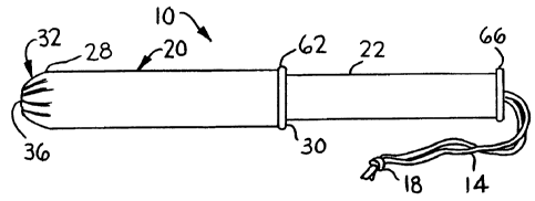
Fig. 1 is a perspective view of a two piece, spirally wound
paper tampon applicator.
Fig. 2 is a cross-sectional view of the tampon applicator shown
in Fig. 1.
Fig. 3 is a left end view of the tampon applicator shown in
Fig. 1 depicting eight pleats.
Fig. 4 is a cross-sectional view of the insertion tip taken
along line 4--4 of Fig. 3 showing an aperture formed through the
insertion tip and the aperture having a side wall aligned essentially
parallel to the central longitudinal axis of the first member.
Fig. 5 is a cross-sectional view of an alternative embodiment of
an insertion tip integrally formed on the first member and having an
aperture formed therethrough wherein the side wall of the aperture is
aligned at an angle to the central longitudinal axis of the first
member.
Fig. 6 is an alternative end view of a tampon applicator
depicting three pleats.
Fig. 7 is still another alternative end view of a tampon
applicator depicting sixteen pleats.
Fig. 8 is a schematic view of a pleat taken along line 8--8 of
Fig. 3 depicting the shape and thickness of a pleat.
Fig. 9 is a cross-sectional view of the insertion tip taken
along line 9--9 of Fig. 3 depicting one end of the pleats extending
into the first member.
Fig. 10 is a cross-sectional view of an alternative embodiment
of the insertion tip showing one end of the pleats terminating at a
point where the insertion tip integrally joins the first member.
Fig. 11 is a cross-sectional view of another embodiment of the
insertion tip showing one end of the pleats terminating at a point on
the exterior surface of the insertion tip.
Fig. 12 is a perspective view of the tampon applicator showing
the pleats in an open arrangement.
- 4 -
21~3083
-
DETAILED DESCRIPTION OF THE PREFERRED EMBODIMENTS
Referring to Figs. 1-3, a tampon applicator 10 is shown which is
designed to house a catamenial tampon 12 and provide a comfortable
means of inserting the tampon 12 into a woman's vagina. A tampon is
an absorbent member primarily designed to be worn by a woman during
her menstrual period to absorb menses, blood and other body fluid.
The tampon 12 can be made from natural or synthetic fibers including
cellulose fibers such as cotton or rayon, or artificial fibers such
as polyester, polypropylene, nylon or blends thereof. Other types of
fibers may also be used, such as cellulose sponge or a sponge formed
from elastomeric materials. A blend of cotton and rayon fibers works
well.
The tampon 12 is normally compressed into the form of a cylinder
and can have a blunt, rounded or shaped forward end. The tampon 12
commonly has a withdrawal string 14 fastened to an end thereof which
serves as a means for withdrawing the soiled tampon from the woman's
vagina. The withdrawal string 14 can be looped through an
aperture 16 formed transversely through the tampon 12. In addition,
the withdrawal string 14 can have a knot 18 formed at it's free end
to assure that the string 14 will not separate from the tampon 12.
The tampon applicator 10 includes a first member 20 and a second
member 22. The first member 20 is preferably in the form of a
spirally wound, convolutely wound or longitudinally seamed hollow
tube which is formed from paper, paperboard, cardboard or a
combination thereof. The first member 20, also commonly referred to
as an outer tube, is fairly rigid and has a relatively small diameter
of about 10 mm to about 20 mm. The first member 20 has a wall 24
with a predetermined thickness of about .2 mm to about .6 mm. The
wall 24 can be constructed from a single ply of material or be formed
from two or more plies which are bonded together to form a laminate.
The use of two or more plies or layers is preferred for it enables
the manufacture to use certain material in the various layers which
can enhance the performance of the tampon applicator 10. When two or
more plies are utilized, all the plies can be spirally wound,
convolutely wound or longitudinally seamed to form an elongated
cylinder. The wall 24 can be constructed using a smooth thin ply of
material on the outside or exterior surface 26 which surrounds a
2143083
coarser and possibly thicker ply. When the wall 24 contains at least
three plies, the middle ply can be the thicker ply and the interior
and exterior plies can be smooth and/or slippery to facilitate
expulsion of the tampon 12 and to facilitate insertion of the first
member 20 into a woman's vagina, respectively. By sandwiching a
thick, coarser ply of material between two thin, smooth plies, an
inexpensive first member 20 can be provided which is very functional.
The wall 24 should contain one to four plies, although more plies can
be utilized if desired.
The plies forming the wall 24 can be held together by an
adhesive, such as glue, or by heat, pressure, ultrasonics, etc. The
adhesive can be either water-soluble or water-insoluble. A
water-soluble adhesive is preferred for environmental reasons in that
the wall 24 will quickly break apart when it is immersed in water.
Such immersion will occur should the first member 20 be disposed of
by flushing it down a toilet. Exposure of the first member 20 to a
municipal's waste treatment plant wherein soaking in water,
interaction with chemicals and agitation all occur, will cause the
wall 24 to break apart and even dissolve in a relatively short period
of time.
The inside diameter of the first member 20 is usually less than
about .75 inches (about 19 mm) and preferably less than about .625
inches (about 16 mm). Although the exterior diameter of tampons do
vary, most tampons utilized by women have an external diameter of
less than about .75 inches (about 19 mm). However, if one desired to
use this invention to administer medication to an animal, such as a
farm animal, larger size tampons 12 could be used.
It should be noted that the first member 20 can be spirally
wound, convolutely wound or longitudinally seamed into a cylindrical
tubular shape. Alternatively, the material can be overlapped into a
tubular configuration. Spirally or convolutely winding the first
member 20 into a cylindrical tube is especially advantageous when the
first member 20 is formed from a laminate. The reason for this is
that when a laminate is circumferentially wound into a tube and a
butt seam or an overlap is formed, the butt seam or the overlap can
interfere with the later formation of pleats on the forward end
thereof. A common problem with a rigid or stiff walled, tubular
2143083
member having a relatively small diameter and a butt seam is that the
seam has a tendency to come apart after formation if exposed to
certain stress forces and/or high humidity. A problem with a tubular
member having an overlap is that a small portion of the wall will be
thicker than the remaining portion and this will cause problems when
one tries to pleat one end of the tube. Accordingly, the first
member 20 should preferably be formed into a cylindrical
configuration without the presence of a butt seam or an overlap.
The first member 20 is sized and configured to house the
absorbent tampon 12. As stated above, the first member 20 should
have a substantially smooth exterior surface 26 which will facilitate
insertion of the first member 20 into a woman's vagina. When the
exterior surface 26 is smooth and/or slippery, the first member 20
will easily slide into a woman's vagina without subjecting the
internal tissues of the vagina to abrasion. The first member 20 can
be coated to give it a high slip characteristic. Wax, polyethylene,
a combination of wax and polyethylene, cellophane and clay are
representative coatings that can be applied to the first member 20 to
facilitate comfortable insertion.
The first member 20 can be a straight, elongated cylindrical
tube formed on a central longitudinal axis X--X. It is also possible
to form the first member 20 into an arcuate shape. The arcuate or
curved shape can assist in providing comfort when inserting the first
member 20 into a-woman's vagina. With a curved tampon applicator, it
is possible to e~ploy a curved tampon which again may be more
comfortable for some women to use since the shape of the tampon may
better fit the curvature of a woman's vagina.
The first member 20 has first and second spaced apart ends 28
and 30, respectively. The first member 20 can also have either a
constant outer diameter or a stepped outer profile. Preferably, the
first member 20 will have an essentially constant diameter over a
major portion of it's length. Integrally formed on the first end 28
of the first member 20 and extending outwardly therefrom is an
insertion tip 32. The insertion tip 32 is designed to facilitate
insertion of the first member 20 into a woman's vagina in a
comfortable manner. The insertion tip 32 is semi-spherical in
configuration and has a diameter which is approximately equal to the
2l43a~3
-
outside diameter of the first member 20. The insertion tip 32 has a
wall 34 with a thickness which is approximately equal to the
thickness of the wall 24 which forms the first member 20. However,
it is possible to construct the wall 34 so that it has a thickness
which is less than or greater than the thickness of the wall 24, if
desired.
Referring to Fig. 4, the insertion tip 32 is shown in
cross-section with the semi-spherical configuration extending outward
away from the first end 28 of the first member 20. The cross-section
of the semi-spherical configuration spans an arc (A) of approximately
180 degrees. The semi-spherical configuration is formed on a
diameter which is sized to be equal to or slightly smaller than the
diameter of the first member 20. For example, if the outside
diameter of the first member 20 is .64 inches (16.2 mm), the
insertion tip 32 can be formed on a radius of about .32 inches (about
8.1 mm).
A relatively small aperture 36 is formed in the center of the
semi-spherical or dome shaped insertion tip 32 and is coaxially
aligned with the longitudinal axis X--X. The aperture 36 can have a
diameter of at least about 1.5 mm, preferably between about 1.5 to
about 5.0 mm, and more preferably, between about 3.0 to about 3.5 mm.
Another way of sizing the diameter of the aperture 40 is to make it
less than about 30YO of the diameter of the first member 20,
preferably, between about 10Y. to about 30% of the diameter of the
first member 20, and most preferably, less than about 20% of the
diameter of the first member 20. It should be noted that although
the aperture 36 is described as a circle, it is possible to form the
aperture 36 in other shapes such as a polygon, a square, a pentagon,
a hexagon, an octagon, etc. The small aperture 36 should extend
through the insertion tip 32 and have a side wall 38 which is aligned
essentially parallel to the longitudinal axis X--X. In addition, the
aperture 36 can be rounded or contain a radius 40 on it's exterior
surface to assure that no sharp edges are present which could pinch
or cut the sensitive tissues of a woman's vagina. The purpose of the
small aperture 36 in the end of the insertion tip 32 is to facilitate
the subsequent unfolding of the pleats during use, as will be
described below. The aperture 36 also assures that the pleats will
21~3083
symmetrically open about the longitudinal axis X--X of the first
member 20. A further benefit of the aperture 36 is that it provides
a visual means for the user to inspect the tampon applicator 10 and
assure herself that a tampon 12 is present in the first member 20.
The design in Fig. 4 is to be contrasted to the embodiment shown
in Fig. 5 wherein an enlarged aperture 42 is depicted having a side
wall 44 which tapers downward and inward to form a sharp point 46
adjacent to an interior surface 48 of the insertion tip 32. The
sharp point 46 is more likely to pinch or trap vaginal tissue and
therefore could cause discomfort during insertion. In addition, the
larger diameter of the aperture 42 exposes a greater area of the
absorbent tampon 12 and this could cause abrasion with the vaginal
tissues during insertion. The embodiment shown in Fig. 4 is more
desirable for comfort.
Referring again to Fig. 4, the configuration of the aperture 36
is preferred for it is smaller in diameter and therefore exposes a
smaller amount of the absorbent tampon 12. Since a tampon is
normally dry and consists of a plurality of absorbent fibers, it can
cause abrasion against the walls of a woman's vagina as it is being
inserted. By reducing the amount of surface area of the tampon 12
which is exposed to the vaginal tissue, one can decrease the
discomfort during the insertion process. In addition, since the
insertion tip 32 is almost closed, it also lowers the frictional
force between the exterior surface 26 of the tampon applicator 10 and
the walls of the vagina. Furthermore, the small diameter of the
aperture 36 also decreases the possibility of trapping or pinching
vaginal tissue therein.
Referring to Figs. 3, 6 and 7, the insertion tip 32 is shown
having a plurality of pleats 50 which can radially open such that the
insertion tip 32 has a diameter approximately equal to or greater
than the diameter of the first member 20. Either an even or an odd
number of pleats 50 can be present and the pleats 50 can be equally
spaced apart or they can be non-uniformly arranged. Uniformly
arranged pleats 50 are preferred but randomly arranged pleats 50 will
work. For ease of manufacturing, it is preferred that the pleats 50
be equally spaced relative to one another. Each pleat 50 is a fold
formed by doubling the material upon itself and then pressing or
21430~3
adhering the material into place. Although eight equally spaced
apart pleats 50 are shown in Fig. 3, it is possible to utilize
various numbers of pleats 50. The number of pleats 50 can vary from
between three to about thirty-two pleats, preferably between about 5
to about sixteen pleats, and most preferably, between about 6 to
about 12 pleats.
In Fig. 6, an embodiment is shown with three equally spaced
pleats 50, while in Fig. 7, sixteen pleats 50 are displayed. The
minimum number of pleats 50 should be no less than three because the
force required to open the insertion tip 32 normally increases as the
number of pleats 50 decrease. If the force becomes too large, the
tampon applicator 10 could bend or deform during the insertion
process and this may cause discomfort. When more than thirty-two
pleats 50 are used, the expulsion force may be lowered but it becomes
difficult to form so many pleats on the insertion tip 32.
Referring to Fig. 8, a schematic view of a pleat 50 is shown.
The pleat 50 is obtained by folding the paper, paperboard, or
cardboard material upon itself so that when each pleat 50 is opened
or unfolded it will occupy a much larger surface area. The thickness
of the material forming the insertion tip 32 can be equal to or
slightly less than the thickness of the first member 20. For the
first member 20, a thickness of about .1 mm to about .7 mm works
fine. The insertion tip 32 can have a thickness between about .1 mm
to about .5 mm. In the folded condition, the pleat 50 has a
thickness, indicated by the letter "t" of less than about 0.7 mm,
preferably between about .25 mm to about .35 mm. Another way of
stating this is to say that the thickness of each pleat 50 in the
folded condition will be greater than twice the thickness of the
material from which the insertion tip 32 is constructed.
Referring to Figs. 9-11, three different embodiments of a pleat
are depicted. In Fig. 9, the pleat 50 is depicted as having a first
end 52 which coincides with the side wall 38 of the aperture 36. In
other words, the first end 52 of the pleat 50 forms a portion of the
arc of the aperture 36. The pleat 50 also has a second end 54 which
coincides with a point located on the exterior surface 26 of the
first member 20. This point is spaced a distance "a" from the
location where the insertion tip 32 is integrally joined to the first
- 10 -
214~Q~3
member 20. By forming the pleat 50 with this particular length, one
can control the amount of force needed to open the insertion tip 32
and push the tampon 12 therethrough. Usually, a lower force is
required to open the pleats when each pleat 50 has a length which
extends into the outer circumference of the first member 20.
In Fig. 9, the semi-spherical tip 32 spans a radial arc,
identified as angle alpha (a), which extends from the first end 52 to
the point where the semi-spherical shaped tip 32 is integrally joined
to the first member 20. The angle alpha (a) is between about 60 to
about 90-, preferably between about 75- to about 90, and most
preferably, greater than 80-. The angle alpha (a) would be 90 if
the aperture 36 was not present. The size of the aperture 36 will
partially determine the exact angle of the insertion tip 32. The
angle alpha (a) should be as close to 90- as possible without
completely enclosing the forward end of the tampon 12.
In Fig. 10, an alternative embodiment of an insertion tip 32' is
depicted wherein a pleat 50' is shown having a first end 52 which
coincides with the side wall 38 of the aperture 36. In other words,
the first end 52 of the pleat 50' forms a portion of the arc of the
aperture 36. The pleat 50' also has a second end 56 which coincides
with the point where the insertion tip 32 is integrally joined to the
first end 28 of the first member 20. By forming the pleat 50' with
this particular length, one can control the amount of force needed to
open the insertion tip 32 and push the tampon 12 therethrough.
Although the force required to open the pleats 50' may be slightly
greater than the force required with the design shown in Fig. 9, the
force is still within acceptable limits.
In Fig. 11, a third embodiment of an insertion tip 32" is
depicted wherein a pleat 50" is shown having a first end 52 which
coincides with the side wall 38 of the aperture 36. In other words,
the first end 52 of the pleat 50" forms a portion of the arc of the
aperture 36. The pleat 50" also has a second end 58 which coincides
with a point located on an exterior surface 60 of the insertion
tip 32. This point is spaced a distance "b" from the location where
the insertion tip 32 is integrally joined to the first end 28 of the
first member 20. By forming the pleat 50" with this particular
length, one can control the amount of force needed to open the
21~3083
insertion tip 32 and push the tampon 12 therethrough. Although the
force required to open the pleats 50" may be greater than the force
required with the designs shown in Figs. 9 and 10, the force is still
within acceptable limits.
It should be noted that both the length and diameter of
commercially available tampons do vary and therefore the tampon
applicators 10 should be manufactured in a variety of sizes. Tampons
can vary in length from about 1 to about 3 inches (about 25.4 mm to
about 76.2 mm) but preferably are about 2 inches (about 50.8 mm) in
length. The tampon diameter will also vary from about .25 inches to
about .75 inches (about 6.4 mm to about 19.0 mm). In addition, the
material from which the tampon 12 is constructed, the smoothness of
the internal surface of the first member 20, the shape of the second
member 22, etc. all contribute to establish a needed expulsion force
to open and expel the tampon 12. This force should range from
between about 250 grams to about 1,500 grams, preferably less than
about 1,200 grams, and most preferably, less than about 1,000 grams.
A lower force value is preferred for it assures that the tampon
applicator 10 will be less susceptible to being bent or deformed as
the tampon 12 is expelled. A bent applicator could cause the tampon
to be inserted incorrectly. A lower force value also makes the
tampon applicator 10 easier to use.
Referring again to Figs. 1 and 2, the first member 20 can have a
fingergrip ring ~62 located approximate the second end 30. The
fingergrip ring 62 can be integrally formed from the material from
which the first member 20 is constructed or it can be a separate
member which is secured in place by an adhesive or some other type of
attachment mechanism. The fingergrip ring 62 functions to provide a
means for the user to grip the first member 20 and hold it between
her thumb and middle finger. The user can then position her
forefinger on the free end of the second member 22 and orient the
first member 20 relative to her vagina while she pushes the second
member 22 into the first member 20.
As stated above, the tampon applicator 10 includes a second
member 22, also commonly referred to as an inner tube. The second
member 22, like the first member 20, can be a spirally wound, a
convolutely wound or a longitudinally seamed hollow tube constructed
21430X3
from paper, paperboard, cardboard, or a combination thereof. The
second member 22 can also be formed into a cylindrical tube by
overlapping the material upon itself. The second member 22 can be
constructed of the same material as the first member 20 or it can be
made out of a different material. Furthermore, the second member 22
could be constructed as a laminate having two or more plies which are
then spirally wound, convolutely wound or longitudinally seamed into
a cylindrical tube. Either a wound tube or a longitudinally seamed
tube is preferred because the finished tube will have a wall 64 with
a constant thickness. However, some manufacturers may prefer to
construct the second member 22 as a solid stick or use some other
unique shape. It is also possible to form a fingergrip ring or
flange 66 on the outer end of the second member 22 to provide an
enlarged surface onto which the user's forefinger can rest. The
fingergrip ring 66 thereby functions as a seat for the forefinger and
facilitates movement of the second member 22 into the first
member 20.
Referring to Fig. 12, the second member 22 functions by being
telescopically movable relative to the first member 20. As the
second member 22 is pushed into the first member 20, the tampon 12 is
forced forward against the pleats 50. The contact by the tampon 12
causes the pleats 50 to radially open to a diameter which is
sufficient to allow the tampon 12 to be expelled from the first
member 20. The open arrangement of the pleats 50 is shown in Fig. 12
after the tampon 12 has been expelled. With the tampon 12 properly
positioned in the woman's vaginal cavity, the tampon applicator 10 is
withdrawn and properly discarded.
The tampon applicator 10 having the semi-spherically shaped
insertion tip 32 works well in combination with a catamenial tampon
having a shaped nose. This is especially true when the shaped nose
on the tampon 12 is configured to conform to the interior surface 48
of the insertion tip 32.
While the invention has been described in conjunction with
several specific embodiments, it is to be understood that many
alternatives, modifications and variations will be apparent to those
skilled in the art in light of the aforegoing description.
- 13 -
214308~
-
Accordingly, this invention is intended to embrace all such
alternatives, modifications and variations which fall within the
spirit and scope of the appended claims.
- 14 -