Note: Descriptions are shown in the official language in which they were submitted.
WO 94/05935 PCT/GB93/01809
..
SEALING MEMBER
The present invention relates to environmental sealing,
especially to a sealing member, particularly for cable accessories for
example housings such as cable splice closures.
Environmental sealing is frequently necessary in the cables
accessories arts in order to keep out contaminants such as water and
sometimes to retain pressure. When cables are spliced, for example,
cable jackets must be removed in order to expose conductors for
connection. Some form of closure must be created around the
otherwise exposed conductors to replace the removed cable jacket.
Such splice closures must have a lifetime under adverse conditions
comparable to that of the cables themselves, which may be twenty
years or so. Thus, the problem of environmental sealing is far from
trivial.
The present invention will find uses in many fields, but it is
expected to be particularly useful for sealing optical fibre splice
closures and other cable or pipe accessories. Cable splice closures
often must be installed under wet or muddy conditions, and it is
desirable that a good seal can be achieved without the need for
rigourous cleaning of the surfaces to be sealed.
An optical fibre closure where the invention is expected to find
particular use is disclosed in European Patent Specification No.
0159857 (Raychem). That specification discloses an assembly
capable of enclosing a butt splice between at least two optical fibre
cables, which comprises:
a hollow article comprising a base plate and a hollow cover
disengageable from the base plate, the base plate having at Ieast two
mutually adjacent outlets capable of receiving respective optical
= fibre cables; the assembly having at least one optical fibre organizer
housed within the article for storing a plurality of optical fibres in a
WO 94/05935 PGT/GB93/01809
r
_.2
path from one of the outlets to another of the outlets, said path
having a minimum radius of curvature no smaller than the minimum
bend radius of said optical fibres; and
first means for connecting the base plate to the hollow cover
and second means for connecting the at least one optical fibre
organizer. to the base plate such that when the first and second
means are so connected the optical fibres are stored in at least one
storage plane and characterized in that when the first means is
disconnected the hollow cover is removeable from the base plate by
being moved along a direction which is substantially parallel to the
storage plane, substantially parallel to each outlet direction at the
base plate and substantially perpendicular to the base plate.
The base plate and cover, which is preferably dome-shaped,
may be held together by some mechanical clamp, optionally together
with some environmental sealing means such as a gasket, O-ring,
mastic seal or adhesive bond.
The use of O-rings in such a device is, of course, well known.
They allow easy re-entry into the closure and easy re-sealing, they
can withstand high pressures within the closure, and they do not
suffer from compression set.
We have, however, become aware of certain disadvantages of
the use of simple O-rings. For example, the force that they are
subjected to and the consequential extent of their distortion are
critical if a good seal is to be obtained. The forces required are
generally high, and as a result the article to be sealed must be strong
and, therefore, generally thick-walled. In the case of an optical fibre
closure as disclosed above, this means that the base and at least the
lower skirt of the dome cover must be ruggedly constructed. A
further disadvantage is that both the O-ring and the surfaces of the
base and dome to be sealed, must be carefully cleaned and must be
free from scratches or moulding flash etc. Dimensional changes
resulting from pressure, heat or excessive mechanical loads might
CA 02143201 2003-04-09
27065-292
3
prevent a good seal being achieved, and performance at low
temperatures is unlikely to be satisfactory due to loss of
elastomeric properties of the materials from which most O-
rings are made.
We have discovered that such disadvantages of
0-rings can be avoided if an 0-ring, or other retaining
member, is used in conjunction with a suitable sealing
material. This new combination produces surprising benefits
not apparent from either component when used separately.
This might be due to the ability of the retaining member to
store energy, as discussed below.
Thus, the present invention provides a sealing
member comprising: (a) a sealing material having a cone
penetration of between 80 and 400 (10-1 mm) and an ultimate
elongation of at least 1000, and (b) an elastomeric
retaining member for the sealing material, which retaining
member comprises two substantially concentric O-rings which
are joined to one another, an annular space between the O-
rings containing the sealing material.
Cone penetration and ultimate elongation are
measured in accordance with American National Standard
Designations ASTM-D217 and ASTM-D638.
The cone penetration is preferably at least 100,
more preferably at least 120, and preferably less than 350,
and in particular less than 200(10-lmm). Ultimate elongation
is preferably at least 200, more preferably at least 4000.
Various materials may be used as the sealing
material, but we prefer a gel. Gels have various
advantages, for example they can be highly conformable at
room temperature since they can have an almost liquid-like
flexibility that allows them to conform to the substrate to
CA 02143201 2003-04-09
27065-292
4
be sealed. They have a cross-linked structure which gives
them elasticity, cohesive strength, and form stability. The
cross-linked structure may result from cross-linking
chemical bonds, as in the case of a silicone or polyurethane
gel, or it may result from the formation of crystalline
regions as in the case of thermoplastic gels such as those
based on block copolymers. Tn any case, the gel will
comprise some form of three-dimensional polymer network,
extended by means of an oil or other material. Gels are
disclosed in US Patent 4600261.
We prefer that the gel be pre-cured, or its
three-dimensional structure otherwise formed, away from the
substrate to be protected. We have found that this is
preferable to the components of a gel being poured between
the surfaces to be sealed, and then cured. Thus, we are
able to pre-form a sealing member which can be easily
handled and stored before being positioned for example
between the base and dome of an optical fibre closure.
The 0-rings, allows the sealing member to be put
under compression along one direction (for example along the
direction along which the dome and base of a splice closure
are brought together), but restricts consequential
displacement of the sealing material in a perpendicular
direction. The retaining member preferably has the function
of storing energy applied when the parts to be sealed are
brought together. Thus, slight displacement of the sealing
material can be compensated for by subsequent relaxation of
the retaining member. In this way the sealing material can
be retained under compression, thereby preventing the
formation of leak paths.
Any suitable material may be used as the
elastomeric retaining member, but we prefer a rubber such as
CA 02143201 2003-04-09
27065-292
a natural rubber, silicone rubber, nitrile rubber, EPDM
rubber or neoprene rubber. The material of the retaining
member preferably has a Shaw A hardness of from 30 to 80,
preferably 40 to 70, more preferably 50 to 60.
5 The retaining member may be hollow, thereby being
pneumatically compressible. Energy can then be stored as
pressurized gas as well as or instead of deformation of the
material of the retaining member itself.
It might be desirable to provide means by which
the sealing material can be held on the retaining member,
and to this end the retaining member may have a surface
provided with indentations or protrusions or treated to aid
bonding between sealing material and retaining member.
As mentioned above the sealing member of the
invention can be used in the environmental protection of an
optical fibre closure, and the invention therefore also
provides an optical fibre or other cable splice closure, or
other housing, that comprises: (1) a first part having a
first surface; (2) a second part having a second surface,
which second surface is, in use, brought towards the first
surface to close the housing; and (3) a sealing member which
comprises (a) a sealing material having a cone penetration
of between 80 and 400 (10-1 mm) and an ultimate elongation of
at least 1000, and (b) an elastomeric retaining member for
the sealing material, which retaining member comprises two
substantially concentric 0-rings which are joined to one
another, an annular space between the 0-rings containing the
sealing material, which sealing member is positioned, in
use, between the first and second surfaces such that
movement of the first and second surfaces together puts the
sealing member under compression and causes the retaining
member to contact each of the first and second surfaces.
CA 02143201 2003-04-09
27065-292
5a
The housing may additionally comprise: (4) means
for maintaining the first and second surfaces in contact
with the retaining member.
WO 94/05935 ~ PCT/GB93/01809
Where the housing comprises an optical fibre splice closure, it
may contain one or more trays or other optical fibre organizers
preferably at the base, and more preferably pivotally attached to the
base. The base may have one or more outlets for receiving cables to
be spliced, and the cables may be sealed in their outlets by any
0
suitable means, for example by means of heat-shrinkable tubing.
The invention is further illustrated with reference to the
accompanying drawings, in which:
Figure 1 shows a prior art optical fibre splice closure;
Figures 2A and 2B show installation of a sealing member
according to the invention;
Figure 3 shows an alternative design of sealing member.
Figure 1 shows an optical fibre splice closure disclosed in EP
0159857. A base plate 1 and a dome-shaped cover 2 together form
an enclosure for use as a butt splice case for optical fibre cables. The
base 1 is preferably manufactured by moulding from a glass fibre
filled high density polyethylene or polypropylene. Outlets 3 may be
provided in the base through which cables pass. On a new
installation, some only of the outlets 3 may be required, and some
may therefore be temporarily blocked as shown at 4. That blocking
may be by any suitable means, but we prefer that the outlet be
made with closed ends which are simply cut off as required. The
dome-shaped cover may be blow moulded and may incorporate a
moisture-vapour barrier such as a metal foil.
The hollow article contains an optical fibre organizer which
comprises a series of trays 5. Each tray preferably includes means 6
for accommodating splice tubes which house fibre splices. The trays
are preferably held in an orderly fashion on a carrier 7 which is
fixed to the base 1. The trays are shown hinged along their short ,
edges, but other hinging for example pivoting or rotation eg about
' one corner in the plane of the trays could be provided. The hinging
allows chosen trays to be exposed for installation of the splices or for
WO 94/05935 PCT/GB93/01809
_ 7 _
repair. Means is preferably also provided for locking trays in a
hinged position.
The assembly of the invention may be used as follows. Firstly,
pass the two cables to be spliced in the direction of the arrows
through two of the outlets 3 such that, say, 1.5 metres of each cable
protrudes into the splice case. The cable jackets are then removed
back to the base 1 to expose 1.5 metres of fibres. The strength core
of each cable is then cut back, leaving enough remaining for it to be
fastened into respective fastening holes 8. Each fibre of one cable is
then spliced to the correct fibre of the other cable. Single fibres,
pairs of fibres, or groups of say 10 or 12 splice fibres may then be
stored on each tray. When one tray is filled it is moved by hinging at
9 to expose another tray. Each tray preferably has a rim 10 to
ensure a sufficient separation between adjacent trays and/or to
prevent fibre slippage from each tray. The splice closure may
additionally or alternatively enclose fibre splitters.
Sealing members of the invention are shown in figures 2 and 3,
and these sealing members may be used in a splice closure as
illustrated in figure 1 in particular to form an environmental seal
between the base 1 and the dome-shaped cover 2.
Figure 2A shows a sealing member before installation, and
figure 2B shows such a sealing member forming an environmental
seal between a base 1 and dome-shaped cover 2. The base 1 is
shown for convenience without its outlets 3, and the cover 2 is only
partially shown.
The sealing member 11 comprises two substantially concentric
O-rings 12, 13 joined together, preferably integrally, by means of a
web 14 extending annularly between them. A gel or other sealing
material 15 is positioned between the O-rings above and below the
annular web 14. The sealing material 15 can be seen to extend
slightly proud of opposing surfaces of the retaining member (here
WO 94/05935 ~ . ~ PCT/GB93/01809
_g-
above and below the top and bottom extremities of the O-rings).
Thus, when the dome 2 and base 1 are brought together with the
sealing member between them, the sealing material 15 is put under
compression as shown in figure ~ 2B. The O-rings 12 and 13 prevent
or restrict displacement of sealing material 15 in a lateral direction
as drawn, ie in a radial direction in the case of a splice closure such
as that shown in figure l; and energy applied can be at least partially
stored by deformation of the O-rings, for example by causing each O-
ring to become oblate in cross-section, and/or by radial expansion of
the outer ring and/or radial compression of the inner ring. Creep or
compression set of the sealing material during service life can
therefore be compensated for at least in part by relaxation of the
retaining member.
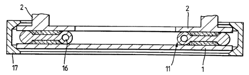
The sealing member shown in figure 3 comprises two O-rings
with a sealing material between them, the annular web of figure 2
being omitted. Also shown in figure 3 is a circular clamp 17, usually
formed in two halves hinged together that can be applied around the
circumference of the base and dome to draw them together. Means
may be provided to maintain the parts of the clamp 17 biased
towards one another thus maintaining the sealing material 15 under
compression. This means (as well as or instead of the retaining
member) may store energy and compensate for creep etc of the
sealing material during service of the closure. One of the O-rings
shown in figure 3 is hollow as shown at 16. In this way the O-ring
can be pneumatically compressible. Both O-rings may, of course, be
hollow.
A low compression force is sufficient to form a seal, and once a
seal has been achieved a wide range of compression forces and a
wide range of relative positions between dome 2 and base 1 can be
taken up without destroying the seal. Small irregularities in the
shape of the dome and base and of the seal itself can be tolerated,
and the various surfaces need not be rigourously cleaned before
installation. The gel preferably wets the surface of the base and the
WO 94/05935 ~ ~ PCT/GB93/01809
-9-
dome since a betterseal results. The of excessive movement
risk of
base and dome avoided by the use of
or of excessive the
pressure is
O-rings or other a result excessive
retaining
member,
and
as
creepage of the is avoided. Also, compression of the gel
gel over can
be avoided becausethe elastic modulus the O-ring may be
of
considerably higher than that of the
gel.