Note: Descriptions are shown in the official language in which they were submitted.
2113465
The present invention relates to ice delivery systems and in
particular to a method and system for the deliver of an aqueous ice slurry.
Aqueous ice slurry generating units and storage systems for such
ice slurry are known in the art. Cooling systems incorporating generating
units
and storage systems of this nature are of interest due to the high cooling
capacity of ice slurry.
An ice storage and distribution unit for ice slurry is disclosed in
Applicant's U.S. Patent No. 4,912,935 issued on April 3, 1990. The ice
storage and distribution unit includes a tank which receives ice slurry
generated
by an ice generating unit. Ice slurry which enters the tank separates into a
brine solution and a floating ice bed on top of the brine solution. An
agitator
is located near the top of the tank and is operable to scrape the ice bed to
discharge ice from the storage tank into an outlet, when it is desired to
distribute ice. When the agitator is operated, make-up brine and/or fresh
water
is added to the outlet to place the ice discharged from the tank back into
slurry
form. The ice slurry is then fed to a positive displacement or centrifugal
pump
which delivers the ice slurry to the desired end location.
Although this ice storage and distribution unit works
satisfactorily, the high inertia of the tank prevents frequent on/off
operation of
the agitator to deliver ice slurry. Also, when a positive displacement pump is
used, the pump must be started and stopped every time ice is discharged from
the tank.
-1-
CA 02143465 2005-02-09
In most cooling systems of this nature, the ice slurry must be delivered
to multiple discharge points positioned at various locations throughout the
system.
Thus, depending on the number of discharge points which are discharging ice
slurry,
the discharge rate of the cooling system may vary. The ice storage and
distribution
unit described in U.S. Patent No. 4,912,935 is not readily adapted for use in
a cooling
system of this nature since it is difficult to operate the agitator in the
tank to deal with
the variable discharge rate of the system as discharge points are turned off
and on.
Also, when only a few discharge points are operational, the velocity of the
ice slurry
in the delivery line may drop below the critical velocity resulting in
separation of the
ice and brine in the ice slurry and therefore, possible plugging of the
delivery line.
It is therefore, an object of the present invention to provide a novel
method and system for the delivery of ice slurry.
Accordingly, in one aspect of the present invention there is provided an
ice slurry delivery system comprising:
an ice slurry circulation loop having an inlet and an outlet to circulate
ice slurry therethrough generally at a first rate;
discharge means located along said circulation loop intermediate said
inlet and outlet actuable to re-direct some of the ice slurry in said
circulation loop to
an end use at a second rate less than said first rate;
an ice generating unit to generate fine particles of ice in an aqueous
solution to create an aqueous ice slurry, said ice generating unit having an
outlet
connected to said circulation loop to deliver ice slurry thereto and having an
inlet
connected to the circulation loop to receive ice slurry from said circulation
loop;
a make-up inlet to deliver aqueous solution to said circulation loop
when said discharge means is actuated to deliver ice slurry to said end use;
and
a flowmeter associated with said make-up inlet to detect delivery of
aqueous solution to said circulation loop, said ice generating unit shutting
off in
response to a signal generated by said flowmeter when delivery of aqueous
solution
into said circulation loop via said make-up inlet is stopped.
-2-
I I
CA 02143465 2005-02-09
Preferably, the circulation loop includes an ice slurry conduit and a
pump along the ice slurry conduit to circulate ice slurry from the storage
tank along
the ice slurry conduit between the inlet anci outlet and the discharge means
is in the
form of at least one valved discharge conduit connected to the ice slurry
conduit. It is
also preferred that pump means is located along at least one of the valved
discharge
conduits to control the delivery of the ice shirry.
According to another aspect of the present invention there is provided
an ice slurry delivery system comprising:
an ice slurry circulation loop, having an inlet and an outlet, to circulate
ice slurry therethrough generally at a first rate;
at least one discharge conduit located along said circulation loop
intermediate said inlet and outlet, said at least one discharge conduit being
actuable to
re-direct some of the ice slurry in said circulation loop to an end use at a
second rate
less than said first rate;
an ice generating unit to geiierate fine particles of ice in an aqueous
solution to create an aqueous ice slurry, said ice generating unit having an
outlet
connected to said circulation loop to deliver ice slurry thereto and having an
inlet
connected to the circulation loop to receive ice slurry from said circulation
loop, said
ice generating unit communicating with at least one detector monitoring a
condition
of said ice slurry delivery system and operating in response thereto to
control the ice
fraction of the ice slurry in said circulation loop; and
a make-up inlet to deliver aqueous solution to said circulation loop
when said at least one discharge conduit is actuated to deliver ice slurry to
said end
use.
According to yet another aspect of the present invention there is
provided an ice slurry delivery system comprising:
a storage tank to hold an aqueous ice slurry having an inlet to receive
fine particles of ice in an aqueous solution;
an ice generator to supply saiii aqueous ice slurry to said storage tank;
-3-
..
CA 02143465 2005-02-09
an ice slurry circulation loop having an inlet and an outlet, both of
which are connected to said storage tank, to circulate ice slurry held in said
storage
tank generally continuously between said inlet and said outlet at a first
rate; and
discharge means located along said circulation loop intermediate said
inlet and outlet to re-direct some of the ice slurry in said circulation loop
to an end
use;
wherein said ice generating unit is responsive to at least one detector
and operates in a manner to control the ice fraction of ice slurry circulated
in said
circulation loop.
According to yet another aspect of the present invention there is
provided an ice slurry delivery system comprising:
an ice slurry circulation loop having an inlet and an outlet, to circulate
ice slurry therethrough generally continuously at a first rate;
discharge means located along said circulation loop intermediate said
inlet and outlet to re-direct some of the ice slurry in said circulation loop
to an end
use;
an ice generating unit to generate fine particles of ice in an aqueous
solution to create an aqueous ice slurry, said ice generating unit having an
outlet
connected to said circulation loop to deliver ice slurry thereto and having an
inlet
connected to the circulation loop to receive ice slurry from said circulation
loop, said
ice generating unit being responsive to at least one detector to control the
ice fraction
of ice slurry circulated in said circulation loop; and
a make-up inlet to deliver aqueous solution to said circulation loop.
According to yet another aspect of the present invention there is
provided a method of delivering ice slurry comprising:
generating an ice slurry via an ice generating unit;
circulating said ice slurry through a circulation loop generally
continuously at a first rate;
selectively discharging some; of the ice slurry from said circulation
loop for an end use; and
-4-
1
CA 02143465 2005-02-09
adjusting the operation of said ice generating unit to control the ice
fraction of said ice slurry circulating in said circulation loop.
According to yet another aspect of the present invention there is
provided an ice slurry delivery system comprising:
an ice slurry circulation loop having an inlet and an outlet, to circulate
ice slurry therethrough generally continuously at a first rate;
discharge means located along said circulation loop intermediate said
inlet and outlet to re-direct some of the ice; slurry in said circulation loop
to an end
use;
an ice generating unit to generate fine particles of ice in an aqueous
solution to create an aqueous ice slurry, said ice generating unit having an
outlet
connected to inlet of said circulation loop to deliver ice slurry thereto and
having an
inlet connected to the outlet of the circulation loop to receive ice slurry
from said
circulation loop, said ice generating unit being responsive to at least one
detector to
control the ice fraction of ice slurry circulated in said circulation loop;
a make-up inlet to deliver aqueous solution to said circulation loop;
and
ice slurry control means for increasing the ice fraction of the ice slurry
when the ice fraction of said ice slurry decreases below a threshold.
According to still yet another aspect of the present invention there is
provided a method of delivering ice slurry comprising the steps of:
generating an ice slurry via ari ice generating unit;
circulating said ice slurry through a circulation loop generally
continuously at a first rate;
selectively discharging some of the ice slurry from said circulation
loop for an end use; and
adjusting the operation of said ice generating unit to increase the ice
fraction of said ice slurry circulating in said circulation loop when the ice
fraction of
said slurry decreases below a threshold.
-4a-
I I= I
CA 02143465 2005-02-09
Embodiments of the preserit invention will now be described more
fully with reference to the accompanying drawings in which:
Figure 1 is a schematic diagram of an aqueous ice slurry delivery
system;
Figure 2 is a schematic diagram of another embodiment of an aqueous
ice slurry delivery system;
Figure 3 is a schematic diagram of another embodiment of an aqueous
ice slurry delivery system;
Figure 4 is a schematic diagi-am of another embodiment of an aqueous
ice slurry delivery system;
Figure 5 is a schematic diagram of another embodiment of an aqueous
ice slurry delivery system;
Figure 6 is a schematic diagram of another embodiment of an aqueous
ice slurry delivery system; and
Figure 7 is a schematic diagram of a food product cooling system.
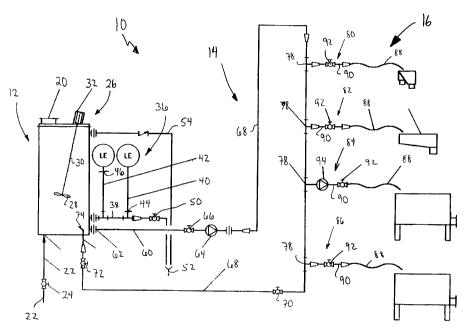
Referring to Figure 1, an aqueous ice slurry delivery system is shown
and is generally indicated by reference nurneral 10. The delivery system 10
includes
a storage tank 12, an ice slurry circulation loop 14 connected to the storage
tank 12
and a plurality of valved discharge points 16 extending from the circulation
loop.
Aqueous ice slurry held in the storage tank ] 2 flows from the
-4b-
2143465
storage tank through the circulation loop 14 and back to the storage tank
generally continuously. However, some of the ice slurry flowing through the
circulation loop 14 can be re-directed from the circulation loop 14 via one or
more of the discharge points 16 for end use.
The storage tank 12 has an inlet 20 at its top to receive fine ice
particles produced by an ice-making machine. An aqueous solution make-up
inlet 22 is connected to the bottom of the storage tank 12 by way of valve 24
and introduces an aqueous solution such as fresh water or brine into the
storage
tank 12. An agitator 26 is also provided on the storage tank 12 to mix the
fine
ice particles and aqueous solution thoroughly within the storage tank. The
agitator 26 includes a mixing blade 28 mounted on one end of a drive shaft 30
extending into the storage tank. A motor 32 located on the top of the storage
tank 12 rotates the drive shaft 30.
A level sensing arrangement 36 is also associated with the storage
tank 12 to detect low and high ice slurry levels within the storage tank. The
level sensing arrangement includes a generally horizontal conduit 38 extending
from the side of the storage tank. 1Wo generally vertical conduits 40 and 42
extend from the horizontal conduit and fill with aqueous solution as the ice
slurry level in the storage tank 12 increases. Conduit 40 has a sensor 44 in
it
which detects a desired low ice slurry level in the storage tank 12. Conduit
42 has a sensor 46 in it which detects a desired high ice slurry level in the
storage tank. The output of the sensors 44 and 46 is used to control the
introduction of fine ice particles into the storage tank 12 via the inlet 20
and as
well as the introduction of aqueous solution into the storage tank 12 via make-
up inlet 22.
-5-
2143465
The horizontal conduit 38 is also connected to a valve 50 which
leads to a drain 52. An overflow conduit 54 extending from the top of the
storage tank 12 also leads to the drain 52.
The circulation loop 14 includes a delivery line 60 coupled to the
storage tank 12 via inlet connection 62 located near the bottom of the storage
tank 12 below conduit 38. Delivery line 60 is connected to a pump 64 by way
of valve 66. Conduit 68 is connected to the discharge port of the pump 64 and
leads back to the storage tank 12. A pair of valves 70 and 72 are positioned
along the conduit 68. The outlet end of conduit 68 terminates within the
storage tank 12 and is, configured to form a nozzle 74 so that ice slurry
discharged by the nozzle 74 assists in the agitation of the ice slurry in the
storage tank.
The valved discharge points 16 are connected to conduit 68 at
spaced locations between pump 64 and valve 70 via T-connections 78. In this
particular embodiment, four discharge points 80 to 86 are shown. Discharge
points 80, 82 and 86 are virtually identical and each includes a flexible
discharge hose 88 connected to conduit 68 by way of a discharge line 90, a
valve 92 and T-connection 78. Discharge point 84 also includes a flexible
discharge hose 88 connected to conduit 68 by way of a valve 92, a discharge
line 90 and T-connection 78. However, discharge point 84 also includes a
positive displacement pump 94 along discharge line 90 to control ice slurry
throughput.
The operation of the ice slurry delivery system 10 will now be
described. When the storage tank 12 is holding ice slurry and the ice slurry
level within the storage tank is above the level of the sensor 46 in conduit
42,
-6-
2143465
valve 24 is closed to prevent additional aqueous solution from entering the
storage tank 12 via make-up inlet 22 and no fine ice particles are introduced
into the storage tank 12 via inlet 20. The motor 32 is powered to rotate the
shaft 30 and hence, the mixing blade 28 to mix thoroughly the ice slurry
within
the storage tank to prevent the ice slurry from separating into its
constituents.
While this occurring, pump 64 draws ice slurry from the storage tank 12 via
inlet connection 62, delivery line 60 and valve 66 and pumps the ice slurry
through the conduit 68. The ice slurry pumped into conduit 68 flows back to
the storage tank (assuming valves 70 and 72 are open) and is discharged into
the storage tank 12 via nozzle 74 to assist in the ice slurry agitation.
When an end user requires ice slurry, one or more of the valves
92 can be opened to allow some of the ice slurry flowing through conduit 68
to flow into the flexible hose 88 via discharge line 90. Ice slurry that does
not
flow through a discharge line 90 is returned back to the storage tank 12 in
the
manner described above.
The pump 64 is designed to ensure that the flow of ice slurry
through the circulation loop 14 is substantially higher than the flow of ice
slurry
through the discharge points 16 even when the valves 92 of all of the
discharge
points are open. This ensures that some ice slurry is always circulating
through
the entire circulation loop 14.
As ice slurry is drawn from the conduit 68 by one or more
discharge points 80 to 86, the ice slurry level in the storage tank 12 drops.
When the ice slurry level in the storage tank 12 drops to a level where the
aqueous solution level in conduit 40 falls below the sensor 44, the sensor 44
provides an output signal. The output of sensor 44 is used to initiate the
supply
-7-
2143465
of aqueous solution into the storage tank 12 by way of make-up inlet 22 and
valve 24 as well as to initiate the supply of fine ice particles into the
storage
tank 12 by way of inlet 20. If the supply rate of the aqueous solution and ice
particles into the storage tank 12 is higher than the rate that ice slurry is
being
drawn from conduit 68 by one or more of the discharge points, then the ice
slurry level within the storage tank 12 will rise. As the level of ice slurry
within the storage tank rises, the aqueous solution level in conduits 40 and
42
also rises. When the level of ice slurry in the storage tank 12 reaches a
level
where the aqueous solution level in conduit 42 reaches the sensor 46, the
sensor
46 provides an output signal which is used to stop the introduction of aqueous
solution into the storage tank 12 via make-up inlet 22 as well as the
introduction
of ice particles into the storage tank via inlet 20.
Although ice slurry delivery system 10 has been described as
including both agitator 26 and nozzle 74 to agitate ice slurry held in the
storage
tank 12, it should be appreciated that only one of these two components needs
to be used to agitate the ice slurry.
Referring now to Figure 2, another embodiment of an ice slurry
delivery system 210 is shown. For the sake of clarity, like reference numerals
will be used to indicate like components with a "200" added for clarity. In
this
embodiment of the ice slurry delivery system 210, the storage tank 212 has a
single inlet 220 which receives ice slurry from an ice generating unit (not
shown) such as that disclosed in Applicant's U.S. Patent No. 4,976,441 issued
on January 10, 1989. The storage tank 212 is larger in dimension then storage
tank 12 shown in the previous embodiment. In order to ensure sufficient
agitation for ice slurry held within the storage tank 212, the shaft 230 of
the
agitator 226 has three spaced mixing blades 228a, 228b and 228c on it. The
-8-
2143465
level sensing arrangement 236 includes a single conduit 240 which has a
horizontal section 238 and a vertical run 242 generally parallel to the
storage
tank 212. Sensors 244 and 246 are located within the vertical run 242 to
detect
low and high ice slurry levels within the storage tank 212.
The circulation loop 214 in this embodiment is very similar to
that in the previous embodiment except that only one valve 270 is located
along
the conduit 268 between pump 264 and storage tank 212. In addition, conduit
268 terminates at a nozzle 274 located near the top of the storage tank 212.
With respect to the discharge points 280 to 286, in this
embodiment, only two of the discharge points 280 and 282 include flexible
discharge hoses 288.
The operation of the ice slurffy delivery system 210 is very
similar to that of ice slurry delivery system 10. In particular, when the
storage
tank 212 is holding ice slurry and the ice slurry level within the storage
tank is
above the level of sensor 246 in vertical run 242, the ice generating unit
(not
shown) is turned off so that no ice slurry is supplied to the storage tank 212
via
inlet 220. The motor 232 is powered to rotate the shaft 230 and hence the
mixing blades 228a to 228c to mix thoroughly the ice slurry within the storage
tank 212. While this occurs, pump 264 draws ice slurry from the storage tank
212 via delivery line 260 and valve 266. The ice slurry is then pumped into
conduit 268 where it circulates through circulation loop 214 before being
discharged into the storage tank 212 via nozzle 274.
When an end user requires ice slurry, one or more of the valves
292 can be opened to allow some of the ice slurry flowing through conduit 268
-9-
2113465
to flow into the discharge lines 290. Ice slurry that does not flow through a
discharge line 290 is returned back to the storage tank 212. Pump 264 is
designed to ensure that the flaw of ice slurry through the circulation loop
214
is substantially higher than the flow of ice slurry through the discharge
points
280 to 286 even when the valves 292 of all of the discharged points 280 to 286
are open. If ice slurry is drawn from conduit 268 via one or more of the
discharge points and the level of ice slurry in the storage tank 212 falls
below
the level of the sensor 244, the output of the sensor 244 is used to start the
ice
generating unit so that ice slurry is introduced into the storage tank 212 by
way
of inlet 220 as well as to stop agitator 226 and pump 264. The ice generating
unit is operated until the ice slurry level in the storage tank 212 reaches
the
level of sensor 246 at which time, the output the sensor 246 is used to stop
the
operation of the ice generating unit and to restart agitator 226 and pump 264.
Referring to Figure 3, yet another embodiment of an ice slurry
delivery system is shown. In this embodiment, like reference numerals will be
used to indicate like components with a "300" added for clarity. The storage
tank 312 includes an inlet chute 320 to allow fine ice particles to be
delivered
into the storage tank. The storage tank 312 also communicates with a conveyor
installation 100 to allow rock salt or other materials to be introduced into
the
storage tank 312. Similar to Figure 1, a make-up inlet 322 communicates with
the storage tank 312 to introduce aqueous solution such as brine or fresh
water
into the storage tank.
The agitator 326 in this embodiment includes an auger type
mixing blade 328 to mix the contents of the storage tank 312 thoroughly. The
level sensing arrangement 336 includes a single sensor 346 mounted on the
storage tank 312. Introduction of aqueous solution via make up inlet 322, fine
-10-
2143465
ice particles via inlet 320 and rock salt of other material by the conveyor
installation 100 into the storage tank 312 continues until the ice slurry
level
within the storage tank 312 reaches the level of sensor 346. Whenever the ice
slurry level in the storage tank 312 drops below the level of sensor 346,
aqueous solution, fine ice particles and other material are introduced into
storage tank 312 to maintain the ice slurry level within the storage tank at a
desired level.
With respect to the discharge points 380 to 384, in this
embodiment, the discharge points include discharge lines 390 which lead to ice
and brine separators 110. The discharge lines 390 may or may not include
valves 392. The separators 110 separate ice from brine to store dry ice and to
collect brine. The brine collectors in the separators 110 are connected to the
conduit 368 downstream of all of the discharge lines 390 by way of pumps 112
and recycle lines 114 so that collected brine in the separators 110 can be
recirculated back to the storage tank 312. Dry ice stored in the separators
110
can be discharged by way of outlet ports 116.
The operation of ice slurry delivery system 310 is basically the
same as the ice slurry delivery systems shown in the previous embodiments.
Accordingly, ice slurry held in the storage tank 312 is circulated through the
circulation loop 314 and returned back to the storage tank 312 at a rate which
is higher than the rate at which ice slurry is drawn from conduit 368 by the
discharge points 380, 382 and 384. However, unlike the previous
embodiments, ice slurry drawn from conduit 368 by the discharge points is
delivered to ice and brine separators 110 by discharge lines 390. The ice
brine
separators 110 separate ice from brine and allow brine collected in the
separators to be returned to conduit 368 by way of recycle lines 114 and pumps
- 11 -
2143465
112. Dry ice stored in the separators 110 can be delivered for end use by
outlet ports 116.
Referring now to Figure 4, yet another embodiment of an ice
slurry delivery system 410 is shown. In this embodiment, like reference
numerals will be used to indicate like components with a "400" added for
clarity. In this embodiment, storage tank 412 is similar to those described in
Applicant's U.S. Patent No. 4,912,935. Thus, the storage tank 412 is divided
into three separate zones, namely a brine zone 130 near the bottom of the
storage tank, an ice bed zone 132 above the brine zone and an ice slurry
mixing
zone 134 above the ice bed zone. The storage tank 412 has an agitator 426
which includes a scraper blade 428 moveable over the top of an ice bed within
the storage tank 412 to remove ice from the ice bed. Inlet 420 is positioned
in
the brine zone 130 and includes an upright nozzle 136 within the storage tank
412 to deliver ice slurry received from an ice generating unit (not shown). A
brine return line 137 is connected to the storage tank 412 in the brine zone
130
to supply brine to the ice generating unit. An overflow conduit 454 extends
from the storage tank 412 and leads to a drain in the event that the storage
tank
is overfilled. A transfer line 139 having a pump 141 along its length is
connected to the storage tank 412 at the brine zone 130 and the ice slurry
mixing zone 134. The pump 141 and transfer line 139 transfer brine solution
from the brine zone 130 to the ice slurry mixing zone 134 to inhibit the ice
bed
in zone 132 from rising and increasing the ice fraction in the ice slurry
created
in zone 134.
In this embodiment, the inlet connection 462 of the circulation
loop 414 is located adjacent the ice slurry mixing zone 134. The outlet nozzle
474 of conduit 468 is connected to the storage ta nk 412 in the ice slurry
mixing
-12-
2143465
zone above the agitator blade 428. The make-up inlet 422 in this embodiment
is not only connected to the bottom of the storage tank 412 by way of valve
424
but it is also connected to a conduit 138. Conduit 138 is connected to conduit
468 near the nozzle 474 by way of valve 140 and T-connection 142. A pump
144 is located along make-up inlet 422 to assist in the delivery of aqueous
solution to the storage tank 412.
The operation of ice slurry delivery system 410 is very similar
to those embodiments previously described. Ice slurry enters the brine zone
130 of storage tank 412 from the ice generating unit via inlet 420 and nozzle
136. When ice slurry enters the brine zone 130, the ice slurry separates into
a body of brine and an ice bed floating on top of the brine. In order to
produce
ice slurry, the agitator 426 is operated to scrape the top of the ice bed
using
blade 428. Initially, aqueous solution is introduced into the top of the
storage
tank 412 by way of make-up inlet 422, pump 144, conduit 138, valve 140 and
nozzle 474 as well as by transfer line 139 and pump 141. The aqueous solution
and scraped ice are mixed by the agitator and are delivered to delivery line
460
by way of inlet connection 462. The pump 464 in turn circulates the ice slurry
through conduit 468 where it is returned to the storage tank 412 via nozzle
474.
Once a steady flow of ice slurry is delivered back into the storage tank 412
by
way of conduit 468, the valve 140 can be closed to stop the introduction of
aqueous solution into the top of the storage tank from the make-up inlet 422.
Similar to the previous embodiments, the agitator 426 and pump
464 are operated to ensure that the flow of ice slurry through conduit 468 is
at
a rate greater than the flow of ice slurry through the discharge points 480 to
484. The level sensor 446 monitors the level of the ice bed in the storage
tank
412 and when the ice bed drops below a desired level, valve 424 is opened to
-13-
2143465
introduce aqueous solution into the storage tank 412 to raise the level of the
ice
bed back to the desired level. Valve 140 is also opened to introduce aqueous
solution into the ice slurry mixing zone 134 to maintain ice slurry created in
the
zone at desired consistency. The ice generating unit is operated periodically
to
introduce ice slurry into the storage tank 412 to maintain an ice bed in zone
132.
If storage tank 412 is flooded by maintaining valves 424 and 140
opened, level sensor 446 can be omitted. The ice fraction in ice slurry
created
in zone 134 can be adjusted by controffing valves 424 and 140 and by operating
pump 141 along transfer line 139.
Referring now to Figure 5, yet another embodiment of an ice
slurry delivery system 510 is shown. In this embodiment, like reference
numerals will be used to indicate like components with a "500" added for
clarity. In this embodiment, the storage tank 512 is in the form of a
centrifugal
cyclone separator having a tangential ice slurry inlet 520 connected to a
supply
line 150 leading from an ice generator 152. Conduit 568 of circulation loop
514 terminates at the storage tank 512 via nozzle 574. Similar to inlet 520,
nozzle 474 is in the form of a tangential inlet. The storage tank 512 has an
outlet to which delivery line 560 is connected. A second outlet 154 also
extends from the storage tank 512 and leads to a pump 156 which in turn is
connected to the ice generating unit 152 by way of return line 158. Similar to
the previous embodiments, make-up inlet 522 leads to the storage tank 512 to
deliver aqueous solution thereto. Delivery of the aqueous solution to the
storage tank via the make-up inlet is assisted by pump 160.
-14-
2143465
In operation of the ice slurry delivery system 510, ice slurry is
delivered to the storage tank 512 by the ice generating unit 152. The ice
slurry
delivered to the storage tank 512 is fed to the circulation loop 514 where it
flows through the circulation loop and is delivered back to the storage tank
512.
Ice slurry can be drawn from the conduit 568 by one or more of the discharge
points 580 to 584 in the manner previously described.
The configuration of the storage tank 512 allows the ice slurry
delivered to the circulation loop 514 to be of a much greater ice fraction
than
the ice slurry produced by the ice generating unit 152. This allows the ice
generating unit to be operated in a manner which reduces energy requirements
while still allowing the system 510 to deliver ice slurry having a high ice
fraction for end use. The operation of the storage tank 512 to achieve this
will
now be described.
As mentioned previously, the inlet 520 and nozzle 574 are
configured as tangential inlets. When ice slurry is delivered to the inlet 520
and nozzle 574, the velocity of the two streams of ice slurry creates a
cyclone
effect inside the storage tank 512. Since the fine ice particles in the ice
slurry
are lighter than the aqueous solution, the fine ice particles conglomerate
near
the centre of the storage tank 512 and are drawn from the storage tank via
delivery line 560 and pump 564. The aqueous solution concentrates near the
outside walls of the storage tank and is fed back to the ice generating unit
152
via outlet 154, pump 156 and return line 158.
Figure 6 shows yet another embodiment of an ice slurry delivery
system 610. In this embodiment, like reference numerals will be used to
indicate like components with a "600" added for clarity. In this embodiment,
-15-
2143465
the storage tank is omitted and the conduit 668 is connected to the delivery
line
660 by way of T-connection 161. Conduit 668 is also connected to the inlet of
an ice generating unit 162 by way of return line 164, valve 166 and T
connection 168. A supply line 170 extends from ice generating unit 162 and
leads to the T-connection 161 to supply ice slurry to the delivery line 660.
In this embodiment, the discharge points 680, 682 and 684 are
connected to the delivery line 660 instead of the conduit 668. Make-up inlet
622 is also connected to the delivery line 660 to introduce aqueous solution
into
the circulation loop 614. A pump 174 and a flowmeter 176 are located along
the make-up inlet 622 to assist in the delivery of aqueous solution to the
circulation loop 614. Ice slurry detection means 178 in the form of a
temperature sensor is located along the delivery line 660.
In operation, the ice generating unit 162 is operated to deliver ice
slurry to the circulation loop 614. Ice slurry delivered into the circulation
loop
is delivered to conduit 668 by way of pump 664. Ice slurry delivered to the
conduit 668 is fed back to the ice generating unit 162 as well as back to the
delivery line 660 by way of T-connection 161 and valve 670. The valves 670
and 166 are adjusted to limit the flow of ice slurry to the ice generating
unit
162 to the desired level.
When ice slurry is flowing through the circulation loop 614, it
can be drawn from delivery line 660 at any or all of the discharge points 680,
682, 684 in the manner described previously.
When ice slurry is drawn from the delivery line 660, the pump
174 and flowmeter 176 are operated to introduce aqueous solution to the
-16-
2143465
delivery line 660 via make-up inlet 622. As ice slurry is drawn from the
circulation loop 614 and replaced with aqueous solution, the ice fraction of
the
ice slurry in the circulation loop decreases. When this occurs, the torque on
the agitators within the ice generating unit 162 also decreases signalling the
ice
generating unit to increase its capacity so that ice slurry is delivered to
the
circulation loop to increase the ice fraction of the ice slurry. When no ice
slurry is being drawn from the delivery line 660 via the discharge points, the
introduction of aqueous solution into the delivery line 660 via the make-up
inlet
622 is stopped. This is detected by the flowmeter 176 which in turn provides
a signal to shut off the ice generating unit 162. Also, when no ice slurry is
being drawn from the delivery line 660 via one or more of the discharge points
680 to 684, the ice fraction and concentration of solution of the ice slurry
in the
delivery line 660 will increase. This results in a drop in the temperature of
the
ice slurry in delivery line 660 which is detected by temperature sensor 178.
The temperature sensor 178 provides output to the ice generating unit 162
causing it to stop when the temperature of ice slurry in the delivery line 660
reaches a preset temperature.
The present ice slurry delivery systems provide advantages in that
ice slurry can be delivered to multiple locations along the circulation loop
without effecting the flow rate of ice slurry and without placing excessive
burden on the ice generating equipment. This is achieved by providing a
storage tank between the ice generating equipment and the discharge points
which acts as a buffer and recirculating ice slurry in the tank through a
circulation loop at a rate which is always greater than the rate at which ice
slurry is drawn from the circulation loop.
-17-
2143465
Figure 7 shows a system for cooling food products such as
vegetables and meat such as for example poultry and fish. As can be seen,
cooling systems 700 includes a mixing tank 702 to which is connected an ice
slurry inlet line 704. A valve 706 is located along the line 704 to control
the
flow of ice slurry into the mixing tank 702. The top of the tank is open and
communicates with a chute 708. The chute delivers food product to be cooled
into the tank 702. A delivery line 710 extends from the bottom of the tank 702
and leads to a pump 712. A supply line 714 extends from the discharge port
of the pump 712 and leads to a dewatering station 716. A bleed line 718 is
located along the supply line 714. An outlet conduit 720 extends from the
dewatering station 716 and leads to a T-connection 722. One of the outlets of
the T-connection 722 has a return line 724 connected to it. Return line 724 is
connected to tank 702 by way of valve 726. The other outlet of the T
connection leads to a discharge conduit 728 by way of valve 730.
The operation of the cooling system 700 will now be described.
Initially, the mixing tank 702 is filled with ice slurry from the ice
generating
unit via lines 704 and valve 706. Once a sufficient amount of ice slurry is
held
in the mixing tank, food product such as vegetables, poultry or fish is
delivered
into the mixing tank by way of chute 708. An agitator (not shown) may
optionally be located within the tank to mix the food product and ice slurry.
The ice slurry and food product mixture exits the mixing tank 702 via delivery
line 710 and is pumped into supply line 714 by pump 712. The supply line 714
is designed to be of a suitable length to ensure good mixing of the food
product
and the ice slurry and so that the food product in the ice slurry becomes
fully
chilled before arriving at the dewatering station 716. The ice slurry and
fully
chilled food product mixture is delivered to the dewatering station 716
wherein
the food product and ice slurry are separated. At this point, the chilled food
-18-
2143465
product is in a form fit for packaging. The ice slurry separated from the
chilled
food product can be returned to the mixing tank 702 by way of lines 720 and
724 and valve 726 or can be discharged from the cooling system 710 by way
of lines 720 and 728 and valve 730.
The cooling system 700 is particularly advantageous in facilities
where food product is to be prepared in one location in the facility and
chilled
and packaged in another location in the facility. Most common facilities of
this
nature prepare the food product at one location and deliver the food product
to
a chiller at a separate location. The food product must then sit in storage
until
it reaches the desired temperature. At that time, the food product can be
removed from storage and packaged. As one should appreciate, the cooling
system 700 allows the food product to be chilled as it is being delivered to
the
packaging location. It has been found that the cooling system 700 is able to
chill food product entering the tank 702 at a temperature between about 80 F
and 90 F to a temperature of between about 30 F to 40 F by the time the food
product leaves the tank 702 and reaches the dewatering station 716.
-19-