Note: Descriptions are shown in the official language in which they were submitted.
94/07057 . ' PCT/US93/08864
- 1 -
BELT TENSIONING SYSTEM BELT TENSIONER THEREFOR AND
METHODS OF MAKING THE SAME
Technical Field
This invention relates to a new belt
tensioning system and to a new belt tensioner
therefor as well as to new methods of making such a
new belt tensioning system and such a new belt
tensioner.
Backqround Art
It is known to provide a belt tensioning
system comprising a support means having an
abutment means, an endless transmission belt
construction carried by the support means and
arranged to move in a certain path relative to the
support means, an arm pivotally mounted to the
support means, a pulley rotatably carried by the
arm and being in engagement with the belt
construction, and a wound coiled spring having
opposed ends, one of which is operatively
interconnected to the abutment means of the support
means and the other of which is operatively
interconnected to the arm, whereby the force of the
wound coiled spring tends to pivot the arm in a
direction that urges the pulley against the belt
construction with a force that tensions the belt
construction. For example, see the U.S. patent to
Henderson, No. 4,886,483.
It is also known to applicants to provide
a belt tensioning system comprising a support means
having an abutment means, an endless transmission
belt construction carried by the support means and
arranged to move in a certain path relative to the
support means, an arm pivotally mounted to the
support means, a pulley rotatably carried by the
arm and being in engagement with the belt
WO 94/07057 ' ,. .. . . . ' ~PCT/US93/088
c
- 2 -
construction, and a wound coiled spring having
opposed ends, one of which is operatively '
interconnected to the abutment means of the support
means and the other of which is operatively '
interconnected to the arm, whereby the force of the
wound coiled spring tends to pivot the arm in a
direction that urges the pulley against the belt
construction with a force that tensions the belt
construction, the arm having a shoulder means for
being engaged by the one of the opposed ends of the
wound coiled spring by the force of the wound
coiled spring so as to permit removal of the arm
and the wound coiled spring as a self-contained
unit from the support means when the arm is pivoted
to a certain position where the shoulder means of
the arm engages the one end of the wound coiled
spring and effectively moves the one end of the
wound coiled spring out of contact with the
abutment means of the support means, the wound
coiled spring comprising a helical spring having
the opposed ends thereof comprising an inner end
and an outer end, the one end of the wound coiled
spring comprising the inner end thereof. For
example see the U.S. patent to Gardner et al, No.
5,190,502.
Disclosure of the Invention
It is one of the features of the
invention of the aforementioned U.S. patent to
Gardner et al, No. 5,190,502, to provide a new belt
tensioning system wherein the belt tensioner
comprises an arm and a wound coiled spring that can
be carried by the arm so as to provide a self-
contained unit and which when assembled to the
support means of the system provides a means to
transfer one end of the spring to an abutment means
~O 94/07057 ~ ' ~ PCT/US93/08864
- 3 -
on the support means so that that end of the spring
will be operatively interconnected to the support
means and permit the force of the spring to provide
a tensioning force on an endless transmission belt
construction that is carried by the support means
to move in an endless path thereon.
In particular, it was found according to
the teachings of that invention that the arm of the
belt tensioner can be provided with a shoulder
means against which the one end of the wound coiled
spring can engage so as to permit the arm and
spring to be a self-contained unit to be inserted
in the belt tensioning system and be removed
therefrom and when assembled to the support means
can transfer the engagement of that one end of the
spring from the shoulder means of the arm to an
abutment means on the support means to effectively
interconnect that one end to the support means,
whereby the force of the spring tends to pivot the
arm in a direction to apply a tensioning force to a
belt, construction that is engaged by a pulley
rotatably carried by the arm.
However, in that invention, the one end
of the spring comprised an inner end of the spring
whereas it is now desired to have the one end of
the spring comprising the outer end of the spring
because the tensioner is to mount to a support
means that is illustrated in FIG. 2 of this patent
application.
Accordingly, one embodiment of this
invention comprises a belt tensioning system
comprising a support means having an abutment
means, an endless transmission belt construction
carried by the support means and arranged to move
in a certain path relative to the support means, an
CA 02143710 2003-08-07
arm pivotally Mounted to the support means, a
pulley rotatably carried by the arm end being in
engagement With the belt Construction, and a wound
coiled spring having opposed ends, one of which is
operatively interconnected to the abutment means of
the guppott means and the other .of which is
operatively interconnected to the arm; whereby the
force of the wound coiled spring tends to pivot the
arm in a direction that urges the pulley against
the belt construction with ~ force that tensions
the belt construction; the arm having a shoulder
means for being engaged by the one of the opposed
ends of the wound coiled spring by the force of the
wound coiled spring so as to permit removal of the
arm and the Wound coiled spring as a self-contained
unit from the support means when the arm is pivoted
to A certain position where the shoulder means of
the arm engages the one end of the Wound coiled
spring and effectively moves the one .end of the
wound coiled Spring out of contact with the
abutment means of the support means,, the wound
coiled spring comprising a helical spring having
the opposed ends thereof comprising an inner end
and an outer end, the one end of the coiled spring
comprising the outer end thereof.
Accordingly, :it is desirable to provide a
new belt tensioning system having one or more of
the novel features of this invention as set forth
above or hereinafter shown or described.
It is also desirable to provide a new
method of making such a belt tensioning system, the
method of this invention having one or more of the
novel features of this invention as set forth above
or hereinafter shown or described.
CA 02143710 2003-08-07
It is desirable to provide a new belt
tensioner for such a belt tensioning system, the
belt tensioner of this invention having one or more
of the novel features of this invention as set
5 forth above or hereinafter shown or described.
It is desirable to provide a new method
of making such a belt tensioner, the method of this
invention having one or more of the novel features
of this invention as set forth above or hereinafter
shown or described.
_erief bescription of the Drawings
The features of the invention, and its
technical advantages, can be seen from the
following description of the preferred embodiments,
together with the claims and the accompanying
drawings, in which:
FiG. 1 is ~ fragmentary perspective view
illustrating the hew bait tensioning system of this
invention utilizing the new belt tensioner of this
invention;
FIG. 2 is a vieut similar to FIG. 1 and
illustrates the support means of the system of FIG.
1 when the belt tensioner end belt construction are
removed therefrom;
FIG. 3 is ate exploded perspective view of
the various parts that form the new belt tensioner
of this invention;
FIG. 4 is an enlarged rear view of the
belt tensiorier of this invention;
FtG. 5 i~ a side view Of the belt
tensivner of FIG. 4 8hd is taken in the direction
of the Arrows 5-5 of ~'IG: d;
FIG. 6 is A fragmentary front view of the
WO 94/07057 . ~ ' p~'/U~93/088~
- 6 -
support means of FIG. 2;
FIG. 7 is a reduced front view
illustrating how the belt tensioner of FIG. 4 is
initially assembled to the support means of FIG. 6;
FIG. 8 is a view similar to FIG. 7 and
illustrates how the belt tensioner of FIG. 7 is to
be pivoted in order to permit the same to apply a
tensioning force to a belt construction that is
illustrated in phantom lines in FIG. 8;
FIG. 9 is a fragmentary cross-sectional
view taken on line 9-9 of FIG. 7;
FIG. 10 is a fragmentary cross-sectional
view taken on line 10-10 of FIG. 9;
FIG. 11 is a fragmentary view similar to
FIG. 10 and illustrates the tensioner disposed in a
tensioning position thereof; and
FIG. 12 is a view similar to FIG. 11 and
illustrates the tensioner of FIG. 11 applying a
tensioning force to a belt construction.
Best Mode for Carrying out the Invention
While the various features of this
invention are hereinafter illustrated and described
as being particularly adapted to provide a belt
tensioner for operating on a belt construction
adapted to move in a certain path, it is to be
understood that the various features of this
invention can be utilized singly or in various
combinations thereof to provide a belt tensioner
for other systems as desired.
Therefore, this invention is not to be
limited to only the embodiment illustrated in the
drawings because the drawings are merely utilized
to illustrate one of the wide variety of uses of
this invention.
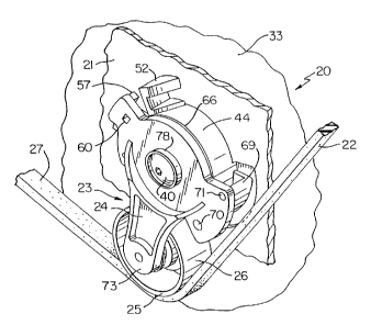
Referring now to FIG. 1, the new belt
CA 02143710 2003-08-07
- 7
tensioning system of this invention is generally
indicted by the reference numeral 20 and comprises
a support mans 21, an endless transmission belt
construction 22 that is carried by the support
means 21 and is arranged to move in a certain path
relative to the support means 21, and a belt
tensioner of this invention that is generally
indicated by the reference numeral 23 for
tensioning the belt construction 22 in a manner
hereinafter set fotth~
The belt tensioner 23 comprises a
metallic of plastic arm 24 that is pivotally
mounted to the support means 21 in a manner
hereinafter set forth and carries a rotatable
pulpy 25 that has a belt engaging surface 26
disposed in toiling sngageMent with the side 27 of
the belt construction 22. The arm 24 and hence the
puiiby 25 .gre normally urgsd in the direction of
the srrow.28 in FIG. 12 by the force of a wound
soiled sp=ing 29 that has one end 30 thereof
operatively interconnected to the support Means 21
in a manner hereinafter set forth and the other end
31 thereof operatively interconnected to the arm
24.
The wound coiled apxing 29 comprises a
helically wound flAt metallic wire spring means
which may have the adjacent coils thereof
interleaved with an anti-friction polymeric strip
32 whereby the spring means 29 functions in a
manner Well known in the art. For example, see the
aforementioned U.S~ patent to Henderson, No.
4,886,483.
The ten9iohet 23 of this invention is
WO 94/07057 , ~ ~, :' ,:; ' ~CT/US93/088~
~ ~. 4 ~'~ ~. 0
_$_
adapted to be inserted into the support means 21
and be removed therefrom, with the spring means 29
being carried thereby in a self-contained manner.
However, the spring means 29 is adapted to have the '
outer end 30 thereof effectively disconnected from
the part 69 of the arm 24 and operatively
interconnected to the support means 21 in a manner
hereinafter set forth so that the force of the
wound coiled spring means 29 tends to pivot the arm
in the direction of the arrow 28 of FIG. 12 so that
the pulley 25 will be urged against the belt
construction 22 with a force that tensions the belt
construction'22 all in a manner and for reasons
that are fully set forth in the aforementioned U.S.
patent to Henderson, No. 4,886,483, whereby only
the details of the structure of the belt tensioning
system 20 and belt tensioner 23 necessary to
understand the features of this invention will be
hereinafter described.
The support means 21 comprises a
supporting structure 33, such as an internal
combustion engine (not shown) of a transportation
vehicle or the like (not shown), the support means
21 being a metallic or plastic cover, mounting
plate or bracket that is fastened to the supporting
structure 33 in any suitable manner, such as by
bolts, whereby the support means 21 is held fixed
to the supporting structure 33.
The support means 21 as illustrated in
FIGS. 2 and 6 has a cylindrical hub 36 that extends
outwardly from a side 37 of the support means 21
and is provided with an internally threaded opening
38 which is adapted to receive an externally
threaded end 39 of a metallic fastening member 40
in a manner hereinafter set forth, the fastening
w0 94/07057 , ~ ~~!' ~ ~ °~ i PCT/US93/08864
_ g _
member 40, as best illustrated in FIGS. 3 and 9,
having an unthreaded enlarged cylindrical shank
portion 41 joined to the threaded portion 39 by a
transversely disposed flat shoulder 42 which is
adapted to engage against a flat shoulder 43 on the
cylindrical part 36 of the support means 21 as
illustrated in FIG. 9 whereby the fastening member
40 is adapted to fasten the tensioner 23 to the
support means 21 in a manner hereinafter set forth
so that the fastening member 40 is fixed from
movement relative to the support means 21.
The support means 21 has an annular wall
44 that extends outwardly from the side 37 thereof
in a concentric manner about the cylindrical hub 36
and has a slot 45 formed therein and defining an
abutment means 46 for having the end 30 of the
spring 29 engaged thereagainst in the manner
illustrated in FIG. 12 to operatively interconnect
the end 30 to the support means 21, as will be
apparent hereinafter.
The wall 44 of the support means 21 has
an inner arcuate surface 47 adapted to be
telescopically disposed with and spaced outwardly
from an outer arcuate surface 48 on a cylindrical
wall 49 of the arm 24 of the belt tensioner 23 in a
manner hereinafter set forth.
The support means 21 .has spaced apart
walls 51 and 52 extending outwardly from the side
37 thereof, with the walls 51 and 52 respectively
defining surfaces 53 and 54 for respectively being
engageable by surfaces 55 and 56 on a stop
extension 57 of the arm 24 of the belt tensioner
23.
In addition, the surfaces 53 and 55 are
initial assembly alignment means. The surfaces 53
WO 94/07057 , . . . . ' HGT/US93/088~
2 ~. 4 3'~ ~ ~
- 10 -
and 55 are parallel such that at initial contact,
the surfaces 53 and 55 meet at one end thereof as
illustrated in FIG. 10.
When the tensioner 23 is first mounted to
the support means 21 as illustrated in FIG. 7, the
fastening member 40 is threaded into the opening 38
in the cylindrical hub 36 and is secured thereto.
Then, when the belt tensioning system 20 is first
utilized to apply tension to the belt construction
22 as shown in FIG. 8, a suitable tool 58 is
disposed in a rectangular opening 60 in the arm 24
by an operator for rotating the arm 24 in the
manner illustrated by the arrow 61 in order to
assemble the belt construction 22 in the system 20
and permit the pulley 25 to apply its tensioning
force when the tool 58 is removed from the opening
60, all in a manner well known in the art.
As best illustrated in FIG. 3, the wall
49 of the arm 24 has a slot 62 therein that
receives a tang 64 on a disc portion 65 of an anti
friction member 66 that is telescoped on the
cylindrical wall 49 and has an arcuate flange 67
for being inserted under the first inner coil 68 of
the spring 29 for the reasons fully set forth in
the aforementioned patent to Henderson, No.
4,886,483.
A part or member 69 forms a portion of
the arm 24 when assembled thereto, the part 69
having a pair of spaced apart posts or rods 70 and
71 that are respectively adapted to be received in
openings 70' and 71' of the arm 24 until a surface '
69' of the part 69 abuts the arm 24 as illustrated
in FIG. 1. The part 69 also has a shoulder means
72 against which the outer end 30 of the spring is
adapted to engage.
~O 94/07057 , ' ~ ~ PCT/US93/08864
- 11 -
In this manner, when the wound coiled
spring 29 is assembled to the arm 24, the inner end
31 of the spring 29 is adapted to be disposed in
the slot 62 of the wall 49 so as to be
interconnected to the arm 24, while the outer end
30 is disposed against the shoulder means 72 of the
part 69, the spring 29 in such assembled condition
still being in a wound condition thereof so that
the same has a force tending to unwind the coils
29' thereof in a manner well known in the art so
that the spring 29 remains in its assembled
condition by the spring force thereof.
The end 31 of the spring 29 is disposed
substantially at a right angle relative to the
inner coil 68 of the spring 29 while the outer end
30 is looped as illustrated in FIGS. 10 and 11.
The spring 29 can have its inner end 31
inserted in the slot 62 of the wall 49 of the arm
24, and the outer end 30 of the spring 29 is
engaged by a suitable tool (not shown) and is wound
into a position beyond the location of the surface
72 of the part 69. The posts 70 and 71 of the part
69 are then disposed respectively into the openings
70' and 71' and are pushed therein. The post 70 is
then affixed to the arm 24 by any suitable means,
such as by bolting, bracketing, staking, soldering
or welding. Thereafter the spring 29 is unwound by
the tool ( not shown ) to engage the surface 30' of
the spring against the shoulder means 72 of the
part 69 which is now part of the arm 24.
The pulley 25 is adapted to be rotatably
mounted on a cylindrical shaft means 73' at the end
73 of the arm 24 and to be fixed thereto, such as
by a threaded fastening member 74, in a manner well
known in the art whereby the pulley 25 is adapted
WO 94/07057 . ~ a '~ ' ~CT/U~93/088~
- 12 -
to rotate relative to the arm 24.
The arm 24 is adapted to be rotatably
mounted on the cylindrical hub 36 of the support
means 21 as will be apparent hereinafter. In
particular, a cylindrical opening 75 passes through
the central hub portion or wall 49 of the arm 24
and is adapted to be lined with a cylindrical
bushing 77 formed of any suitable anti-friction
material, such as a polymeric material, that has an
enlarged flanged end 78 adapted to be disposed
against a side 79 of the arm 24 as illustrated in
FIG. 9.
In this manner, the fastening member 40
is adapted to have the cylindrical portion 41
thereof disposed in an opening 80 of the
cylindrical portion of the bushing 77 as
illustrated in FIG. 9, and to have an enlarged head
81 thereof compact a biasing means, such as the
wavy washer 82, between the head 81 and the flange
structure 78 of the bushing 77 so as to compact the
same against the side 79 of the arm 24 when the
threaded portion 39 of the fastening member 40 is
fully threaded into the threaded opening 38 of the
support means 21 in the manner illustrated in FIG.
9. In this manner, the flat shoulder 42 of the
fastening member 40 abuts against the flat shoulder
43 of the projection 36 as illustrated in FIG. 9
whereby the fastening member 40 is held from
rotation while the arm 24 is adapted to pivot or
rotate relative thereto on the bushing 77 and,
thus, to pivot relative to the support means 21
even though the force of the biasing means 82 has
axially moved the arm 24 on the fastening member 40 '
until the disc portion 65 of the anti-friction
member 66 engages a facing surface means 85 of the
~O 94/07057 ~ ~ PCT/US93/08864
- 13 -
annular wall 44 of the support means 21 for
subsequent sliding movement thereon.
However, in order to retain the fastening
member 40 in its assembled relation with the arm 24
and spring 29 when the belt tensioner 23 is
separate from the support means 21, the cylindrical
bushing 77 has a raised ledge 76 which engages with
the fastening member 40 in an annular slot 42'
thereof in its assembled relation with the bushing
77 and the arm 24 to retain the fastening member 40
thereto. The bushing 77 has means 77' at the end
thereof for snap-fitting to the annular wall
portion 49 of the arm 24 when completely pushed
through the opening 75 of the wall 49 as
illustrated in FIG. 9.
Thus, it can be seen that the belt
tensioner 23 of this invention can be formed of
relatively few parts by the method of this
invention to provide a self-contained unit that
comprises the arm 24, the pulley 25 and the wound
coiled spring 29, which results in a relatively
inexpensive belt tensioner through the change in
the design thereof over the design of prior known
belt tensioners, such as the belt tensioner set
forth in the aforementioned U. S. patent to
Henderson, No. 4,866,483.
When it is desired to. assemble the belt
tensioner 23 of this invention, in the system 20
which has the support means 21 previously fastened
to or to be subsequently fastened to the support
structure 33 by the bolts or other means in the
manner previously set forth, the belt tensioner 23
is assembled thereto in the manner illustrated in
FIGS. 7 and 10 whereby the outer end 30 of the
spring 29 is disposed in the slot 45 of the wall 44
WO 94/07057 ~- ~ ~ ~- IPCT/US93/088
- 14 -
and the surface means 55 and 56 of the arm 24 are
disposed between the means surface 53 and 54 of the
support means 21 while the stop surface 55 of the
extension 57 slides in spaced relation past the
stop surface 53 of the wall 51 of the support means
21. In addition, the wall 49 telescopes over the
wall 36 of the support means 21 and the outer end
30 of the spring 29 slips over the abutment means
46 of the wall 44 of the support means 21 in the
manner illustrated in FIG. 10.
The fastening member 40 then has its
threaded portion 39 threaded into the threaded
opening 38 of the projection 36 until the annular
shoulder 42 of the fastening member 40 abuts
against the surface 43 of the projection 36 in the
manner illustrated in FIG. 9 so that the biasing
means 82 is compacted between the enlarged head 81
of the fastening member 40 and the flange 78 of the
bushing 77 so as to compact the flange 78 of the
bushing 77 against the side 79 of the arm 24 and
compact the disc portion 65 of the member 66
against the facing surface means 85 of the annular
wall 44 of the support means 21.
In this manner, the belt tensioner 23 is
fully assembled to the support means 21 and can be
disposed in its operative position for tensioning
the endless transmission belt construction 22 in a
manner now to be described.
Once it is desired to cause the belt
tensioner 23 to tension the belt construction 22,
an appropriate tool 58 is inserted in the opening
60 of the arm 24 and is then utilized to rotate the
arm 24 in the clockwise direction as represented by
the arrow 61 in FIG. 8 to cause the outer end 30 of
the spring 29 to have its side 30' be placed
~O 94/07057 a ~ ~ ~ ~ PCT/US93/08864
fE ~ .
- 15 -
against the abutment 46 of the wall 44 of the
support means 21 as the shoulder 72 of the part 69
of the rotating arm 24 moves out of engagement with
the surface 30' of the outer end 30 of the spring
29 so that the outer end 30 of the spring 29 is now
operatively interconnected to the support means 21,
such rotation of the arm 24 in the clockwise
direction as illustrated in FIGS. 8 and 11 by the
arrow 61 causing the inner end 31 of the spring 29
to be moved in a direction to further wind up the
spring 29. In this manner, when the side 27 of the
belt 22 is placed against the surface 26 of the
pulley 25 a.n the manner illustrated in FIGS. 1, 8
and 12, the force of the spring 29 tending to
unwind the spring 29 is now applied against the
side 27 of the belt construction 22 as represented
by the arrow 28 in FIG. 12 to tension the belt
construction 22 in a manner well known in the art.
Such tensioning position of the belt tensioner 23
has the arm 24 with its surfaces 55 and 56 disposed
intermediate the surfaces 53 and 54 on the support
means 21 as illustrated in FIG. 12.
When it is desired to remove the belt
tensioner 23 from the support means 21, the belt
construction 22 is removed from contact with the
pulley 25 and the arm 24 is permitted to move in a
counter clockwise direction until the stop surface
55 thereof engages against the stop surface 53 of
the support means 21 at which time the shoulder 72
of the part 69 of the rotating arm 24 now comes
into engagement with the surface 30' of the outer
end 30 of the spring 29 and, in effect, removes the
surface 30' of the outer end 30 of the spring 29
from the abutment 46 of the support means 21 so
that the outer end 30 of the spring 29 is no longer
WO 94/07057 " ': ~ ~ ~' , '. ' ~GT/US93/088~
- 16 -
operatively interconnected to the support means 21.
At this time, the fastening member 40 can be
removed from the threaded opening 38 of the support
means 21 and the belt tensioner 23 can be removed
as a self-contained unit from the support means 21
as the spring 29 is carried thereby.
Thus, another belt tensioner 23 of this
invention can now be utilized with the support
means 21 in the manner previously set forth should
the reason for having removed the previous belt
tensioner 23 be to replace the same.
In any event, it can be seen that this
invention not only provides a new belt tensioning
system and a new belt tensioner therefor, but also
this invention provides new methods of making such
a new belt tensioning system and such a new belt
tensioner.
While the forms and methods of this
invention now preferred have been illustrated and
described as required, it is to be understood that
other forms and method steps can be utilized and
still fall within the scope of the appended claims,
wherein each claim sets forth what is believed to
be known in each claim prior to this invention in
the portion of each claim that is disposed before
the terms "the improvement", and sets forth what is
believed to be new in each claim according to this
invention in the portion of each claim that is
disposed after the terms "the improvement", whereby
it is believed that each claim sets forth a novel,
useful and unobvious invention.