Note: Descriptions are shown in the official language in which they were submitted.
~ 094/05891 ~14 ~ 7 3 ~ PCTtGB93/01837
-- 1 --
DRILL STRING ANCHOR
The present invention relates to an anchor for use
in a drill string.
Drill strings are subjected to variations in the
~luid pressure in the well bore. These variations in
pressure can cause any tool mounted on the string to move
axially within the bore, and this axial movement can affect
the accurate operation of the tool. In particular, if a
drill string carrying a cutting tool is caused to expand or
contract by changes in fluid pressure, the accuracy of the
cutting operation will be impaired. Any unscheduled axial
movement of the tool would cause the cutters to trace a
spiral path in the well bore. One cause of undesirable tool
movement is pulsations in the fluid pressure within the
drill string resulting from operation of the mud pumps.
It would therefore be desirable to be able to
anchor the drill string at a particular location to prevent
axial movement of the tool in the well bore.
Axial movement caused by well bore pressure
changes is particularly noticeable on small diameter work
strings and coiled tubing In general, the smaller the
diameter of the string, the greater the e~ect becomes. In
order to ensure that a cutting tool will cut successfully
and accurately it is clearly necessary to hold the tool
against axial movement.
The anchor of the present invention has been
SUB~ 11 l ~)TE SHEET
CA 0214373~ 1998-04-27
~ - 2 -
developed to endeavour to prevent any axial movement of a drill string at the
location of the anchor as fluid pressure in the drill string or annulus is varied.
The anchor may be used with any other tool which requires location at a
specific depth within a tubing or casing of a well bore.
An aspect of the invention is as follows:
A drill string anchor for use in a well bore, the anchor comprising: a
body; a through bore; and a plurality of anchor assemblies, each assembly
comprising an anchor member, a piston supported within the body, and a
biasing means, the piston being radially movable in response to fluid
10 pressure in the through bore between a first retracted position and a second
extended position in which the piston drives the anchor member into contact
with the wall of the well bore, and the biasing means acting to provide a force
biasing the piston towards the first retracted position, characterised in that
the effective area of the piston which is exposed to the fluid pressure in the
15 through bore when the piston is in the first retracted position is smaller than
the effective area of the piston which is exposed to the fluid pressure in the
through bore when the piston is displaced from the first retracted position.
Preferably the inner face of the piston is exposed to the fluid pressure
in the through bore, and the outer face of the piston is toothed to constitute
20 the anchor member. The biassing force may be provided by any suitable
means such as a coil spring or belville washers, and in the particularly
preferred embodiment is provided by a leaf spring. The leaf spring may be
fixed to the body at one end, the other end of the leaf spring engaging the
piston.
Preferably, each anchor assembly additionally comprises a stop means
for limiting radial extension of the piston. Each anchor assembly may also
comprise a bleed passage between the inner and outer faces of the piston and
a check valve may fitted to the bleed passage.
In a particularly ~re~el ~ed embodiment of the present invention the
30 anchor has two axially separated sets of anchor assemblies, each set
comprising three equi-angularly spaced anchor assemblies, the two sets being
circumferentially offset by sixty degrees with respect to each other.
094/05891 ~ ~ 73 ~ PCT/GB93/01837
The present invention will now be described in
more detail with reference to the accompanying drawings, in
which:
Figure 1 is a quarter cross-section of an anchor
of the present invention showing details of one embodiment
of anchor assembly;
Figure 2 is a diagrammatic longitudinal view of a
preferred embodiment of the anchor; and
Figure 3 is a quarter cross-section of an anchor
showing details of an alternative embodiment of an anchor
assembly.
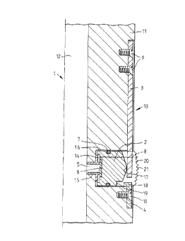
Referring first to Figure 1, an anchor 1 has a
body 11, a central through bore 12, and a plurality of
anchor assemblies 13. Only one such anchor assembly 13 is
shown in Figure 1. Each anchor assembly comprises a piston
2 movable in a chamber 16, a return spring 3 and a stop 4.
A passage 5 allows communication between the through bore 12
and the inner face 14 of the piston. A seat member 6 is
provided on the inner face of the piston. A sleeve 15 may
be provided as a lining for passage 5, and seat member 6
seals against the sleeve 15 when the piston 2 is in the
retracted position.
In Figure 1 the return spring 3 is shown as a leaf
spring which has one end fixed to the body 11 by any
suitable means such as screws 9. The other end of the leaf
spring rests against an end face 17 of the piston 2 to bias
the piston towards the retracted position. The end face 17
is preferably convexly curved to reduce friction and wear
between the piston and the leaf spring.
An outer portion 2~ extends from the piston 2 and
provides a toothed or serrated outer face 21 which
constitutes an anchor member. A leakage or bleed passage 8
extends from the inner face 14 of the piston to the outer
face 21. The piston is sealed in the chamber 16 by means of
a seal assembly 7 such as an O-ring seal.
WO94/05891 PCT/GB93/01837
~ 3~ ~S 4 _ ~
The stop 4 has an inwardly directed protrusion 18
which is adapted to engage with a shoulder 19 on the piston
2 when the piston is in its extended position, to prevent
any further extension of the piston. Stop 4 is fixed to the
body of the anchor by any suitable means such as screw 10.
In operation, if pressure within the through bore
is increased the internal pressure acts on the seat 6 of
piston 2 through passage 5. The pressure thus acts against
the biassing force of the spring 3 The passage 5 may have
a variable size determined by the size of the aperture in
sleeve 15. The size of passage 5 is selected such that the
biassing force of the spring 3 is overcome at a particular,
selected pressure. The piston 2 then moves radially
outwardly in chamber 16, until the outer toothed face 21
contacts and engages with the internal wall of the well bore
tubing or casing or the like (not shown). As the piston 2
lifts off sleeve 15, the full area of the inner face 14 of
the piston is exposed to the internal pressure in the
through bore 12, thus increasing the force exerted by the
toothed face 21 on the internal wall of the well bore.
The radially outward movement or stroke of the
piston 2 is limited by engagement of the shoulder 19 with
protrusion 18 on the stop 4.
When pressure in the through bore 12 drops, the
spring 3 returns the piston to its retracted position seated
against sleeve 15 by displacing any fluid in the chamber 16
behind the piston out through the leakage passage 8 to the
outer face 21 of the piston
If the piston does not seat fully home in the
retracted position once fluid pressure in the bore 12 is
reduced, upward movement of the tool would cause the spring
to lever the piston home sufficiently to allow the drill
string to be withdrawn from the well bore.
By varying the size of passage 5 it is possible to
adjust the opening pressure of the tool, the pressure being
~ 094/05891 2~ ~73~
dependent on the relationship between spring ~orce and the
primary piston area, i.e. the area o~ the seat initially
exposed to the pressure in bore 12 when the piston is fully
retracted. The secondary piston area, i.e. the area o~
inner face 14, allows the pressure to develop the outwardly
directed force sufficient to hold the drill string against
axial movement by means of the tooth formations on outer
face 21.
In operation, whilst the piston is held away from
its seat against sleeve 15, the pressurised fluid in the
bore 12 will bleed off through passage 8, but this passage
is sized or restricted such that the fluid flow, and the
consequent loss of ~luid, are minimised. A miniature check
valve (not shown) could if desired be fitted to control the
loss of fluid from passage 8, such that when under positive
pressure from internal fluid the check valve closes, and at
a lower pressure the valve opens when the spring acts to
return the piston to its retracted position, allowing fluid
to vent via passage 8 from chamber 16.
An anchor according to the present invention is
formed with a plurality of anchor assemblies. The pre~erred
embodiment shown in Figure 2 comprises a first set 22 of
anchor assemblies axially spaced from a second set 23 of
anchor assemblies on the anchor body 11. Each set of anchor
assemblies 22, 23 comprises three anchor assemblies 13
circumferentially spaced at 120 degrees to each other. The
first set 22 is circumferentially offset by sixty degrees
from the second set 23.
As shown in Figure 2, the anchor may be formed as
a sub for connection in a drill string, the anchor body 11
having a connection pin or box thread 24 at either end, the
drill string being inserted into tubing 25 and being
anchored against longitudinal axial movement with respect to
the tubing.
Figure 3 shows a similar view to that shown in
WO94/05891 PCT/GB93/01837 ~
~33
Figure l and like reference numerals will be used for like
parts. In the anchor l of Figure 3, the leaf spring has
been replaced by a coil spring 26, Belville washers could be
used instead of the coil spring 26. The coil spring is
retained in position by means of a recess 27 in the piston
2, and by means of a guide pin 28 on a plate 29 fixed to the
anchor body and spanning the width or length o~ the piston.
The coil spring is compressed as the piston is extended
under ~luid pressure in the bore 12, and once the fluid
pressure drops, the coil spring acts to return the piston to
the retracted position. The plate 29 also acts as a stop
member to prevent extension of the piston 2 beyond the
maximum desired position of extension.
The anchor of the present invention is intended
particularly for use with small diameter work strings and
within small tubing sizes, but its application is not
intended to be limited to such small dimension drill
strings.
Since the anchor of the present invention supports
the drill string and anchors it against movement in the well
bore, the drill string should be run with a downhole motor
below the anchor to provide the rotation of the cutting
tool.
Although the anchor has been described embodied as
a separate sub it will be appreciated that the anchor may be
provided as part of a tool, for example a cutting tool.
Whilst in the preferred embodiment the anchor
members are constituted by the radially outer extremities of
the pistons it will be appreciated that separate anchor
members in direct or indirect contact with the pistons may
be used if desired.