Note: Descriptions are shown in the official language in which they were submitted.
21~4078
W094/09203 ~ PCT/US93/09229
COMPLETELY COU~TF.RCURR~NT COOK CONTINUOUS DIGESTER
BACKGROVND AND SUMMARY OF THE INVENTIOI~
Over the last decade, two significant advances
have taken place in continuous cooking technology
for the production of cellulosic pulp, primarily in
the practice of the sulphate process, but also for
use in the sulfite and other processes. First, with
IM
the advent of MCC digesters from Kamyr, Inc., a
significant countercurrent cook zone was est~blished
in the middle of the digester by introducing white
liquor into a central recirculation loop.
Subsequently, EMCC digesters developed by Kamyr,
Inc., provided for further countercurrent cooking hy
introducing white liquor into the bottom (wash)
circulation loop, as seen in copending application
Serial No. 07/583,043, filed September 17, 19'30.
These digesters have been commercially successf~ll
because they enhance the ~uality of the pulp
produced. In both these commercial digesters,
however, the first cooking zone is a co-current zone.
According to the present invention it ha~ been
found that if the entire cook in a continuous
digester is made countercurrent, the temperatllre of
the cook can be lowered, or more uniform and better
temperature control can be provided. Lower
temperatures or more uniform temperature control
limits the damage to fibers that large temperature
swings can cause, resulting in a better quality
fiber, and therefore increased strength and yield of
pulp .
W094/09203 PCT/US93/09229 ~
21~4078
While it is desirable to take advantage of the
improvements compared to conventional cooks set
forth above, under some circumstances it may still
be desirable to run a digester with conventional
processes, e.g. run it as an EMCC digester.
Therefore, it is desirable to construct a digester
that can be switched over from the completely
countercurrent process of the invention, to a
conventional form of digester, such as an RMCC
digester.
According to the method of the present
invention, cellulosic pulp is produced from
comminuted cellulosic fibrous material utilizing an
upright digester having a top and a bottom. The
method comprises the following steps:
(a) Continuously introducing comminuted cellulosic
fibrous material entrained in cooking liquor into
the top of the digester ~o that the material
continuously moves downwardly in the digester
(b) Continuously withdrawing cellulose pulp from the
bottom of the digester. And, (c) establishin~
countercurrent flow between cooking liquor and
material throughout the entire height of the
digester between the material introduction at the
top and the pulp withdrawal at the bottom, in~ ding
continuously withdrawing liquid from the dige~ter at
various points and reintroducing the withdrawn
liquid.
Preferably the digester is part of a two--vessel
hydraulic system, which includes an impregnation
vessel operatively connected to the inlet to the
digester. In that case, step (c) is practiced in
part by continuously withdrawing liquid from the top
~ W094/09203 2 1 4 4 0 7 8 PCT/US93/09229
of the digester to a top extraction, recirculating a
part of the liquid with any entrained material, to
the impregnation vessel, and continuously removing a
part of the withdrawn liquid from the
digester-impregnation vessel loop (typically feeding
it to a flash tank). The removed liquid has
dissolved lignin therein (i.e. is "black liquor"),
and is handled in the same way that black liquor is
conventionally handled.
Also according to the invention, in order to
prevent hot cooking liquors from entering the
recirculation line back to the impregnation vessel,
and thus reacting with incoming uncooked chips
(which would cause the cooking chemical to be
consumed before extraction could occur and thus
result in low or no residual cooking chemical in the
extracte~ liquor, and subsequent non-uniform
cooking), a cooling circuit is provided at the top
of the digester after the top extraction. The other
liquids withdrawn from a mid-point of the digester,
and the bottom of a digester, which are recirculated
are heated so that cooking does take place below the
cooling circulation.
In order to convert from the complete
countercurrent continuous cook according to the
invention to conventional cooking techniques, an
upper mid-point extraction screen, between the top
extraction and the mid-point extraction, can be
maintained in place, cut off by a valve. When the
valve is open, and a valve from the top extraction
to the flash tank closed, conventional EMCC
treatment may be practiced. Under these
circumstances, a valve in a white liquor line for
W O 94/09203 PC~r/US93/09229 ~
2~4~078
adding white liquor to the bottom circulation can
also be opened, or alternatively white liquor can be
added to the bottom circulation even during complete
countercurrent cook.
The invention also comprises a continuous
digester including: An upright hydraulic vessel
having a top and a bottom. An inlet for cellu]ose
material entrained in liquid at the top of the
vessel. An outlet for cellulose pulp at the bottom
of the vessel. A top extraction, adjacent the top
of the vessel, for withdrawing liquid from the top
of the vessel. A top circulation loop connected to
the top extraction and including a first conduit for
removing a substantial volume of liquid from that
withdrawn through the top extraction and utilizing
it 80 that it is not reintroduced into the ves~el,
and a second conauit for recirculating liquid not
removed, so that it returns to the impregnation
vessel. A mid-point extraction for withdrawing
li~id from the vessel. A mid-point circulation
loop connected to the mid-point extraction and for
reintroducing liquid extracted from the mid-point
extraction 80 that it flows upwardly in the vesfiel.
A bottom extraction for withdrawing liquid ~rom the
vessel. And, a bottom extraction loop connected to
the bottom extraction for reintroducing liquid
extracted from the bottom extraction 80 that it
flows upwardly in the vessel.
The top circulation may include an in-line
drainer from which the first and second conduits
extend, and the digester may be in combination with
the hydraulic impregnation vessel connected to the
inlet to the vessel and to the second conduit. A
~14407~
cooling recirculation loop may be connected to the digester
adjacent, but below, the top extraction, including the cooler.
An upper mid-point extraction may be provided between the top
extraction and the mid-point extraction, including an
extraction conduit; and a first valve means is disposed in the
first conduit, and second valve means is disposed in the upper
mid-point extraction conduit. A control, such as a computer
control, controls the first and second valve means so that
when one is open the other is closed. A flash tank is
connected to the first conduit and the upper mid-point
extraction downstream of the valve means. The extractions
typically include screens mounted within the digester.
It is the primary object of the present invention to provide
an advantageous apparatus and method for continuous
countercurrent cooking of cellulosic fibrous material to
produce cellulose pulp. It is a further object of the present
invention to provide versatility for switching back from the
completely countercurrent cooking to more conventional cooking
techniques. This and other objects of the invention will
become clear from the detailed description of the invention
and from the appended claims.
BRIEF DESCRIPTION OF THE DRAWINGS
2S
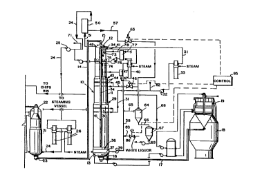
FIGURE 1 is a schematic view of an exemplary continous
digester according to the present invention, shown
interconnected to other cooperating components of a mill for
producing cellulose pulp;
AMENOED SHEET
~ W094/09203 2 1 ~ 4 Q ~ 8 PCT/US93/09229
FIGURE 2 is an enlarged schematic side view,
partly in cross-section and partly in elevation, of
an exemplary in-line drainer, of the apparatus of
FIGURE 1, shown interconnected to related
components; and
FIGURE 3 is a schematic view, partly in cross
section and partly in elevation, of details of the
top of the digester and associated component.s from
FIGURE 1.
DETAILED n~SC~IPTION OF T~E DRAWINGS
The apparatus illustrated in FIGURE 1 comprises
as the main component thereof a continuous digester
10, comprising an upright vessel 11 having a top 12
and a bottom 13. Leading into the top 12 is a line
14 to an inlet 15 at the top 12, t~e inlet 15
introducing comminuted cellulosic fibrous material
(typically wood chips) entrained in cooking li~lor
(e.g. sulphate liquor, sulfite liqllor, or the
like). From the bottom 13 of the digester vessel
11, a pulp discharge 16 is provided, including a
discharge line 17 leading to a high density storage
tank 18 or the like, which may have a two stage
diffusion washer 19 on top of it, as is conve~ltional.
The components to which the digester lO are
connected are conventional for continuous digesters,
Ruch as those produced and marketed by Kamyr, Inc.,
of Glens Falls, New York. The components typically
include a chips bin, chips meter, steaming vessel,
high pressure feeder, sand separator, level tank,
etc., which are well known and not shown in FIGURE
1. Other conventional components typically also
~ W094/09203 2 1 ~ ~ 0 7 8 PCT/US93/09229
include a conventional hydraulic impregnation vessel
21 which includes ~ top separator 22 at the top
thereof connected to the high pressure side of the
conventional high pressure feeder, and an outlet
device 23 at the bottom which is connected to the
line 14. As is also conventional, some of the
liquid is removed from the vessel 11 (which is a
hydraulic vessel) at the top thereof through a line
24 having a pump 25 therein, and is heated by
heaters 26 and then reintroduced through line 2
into the bottom of the impregnation vessel 21.
Also conventional and associated with the
digester 10 is a mid-point extraction, shown
generally by reference numeral 29, including one or
more extraction screens 30 mounted within the vessel
and an extraction conduit 31 extending therefrom
connected to a pump 32, an MCC circulation heater
33, and a return conduit 34 which reintroduces the
heated withdrawn liquor from the screens 30 b~ck
into the v~essel 11 near the vGlume from which it was
withdrawn. Also, as is conventional for a two
vessel Kamyr, Inc., hydraulic digester set-up, a
bottom extraction -- shown generally by reference
numeral 36 -- is provided, including an interior
extraction screen 37 connected to an extraction line
38 having a pump 39 therein, a heater 40, and A
reintroduction conduit 41 for reintroducing liquid
withdrawn by the screen 30 back into the vessel 11
near the volume from where it was withdrawn.
A conventional continuous digester also has the
upper mid-point extraction, shown generally by
reference numeral 43, including interior screen or
screen sets 44, and an extraction line 45. However
W094/09203 PCT/US93/09229 -
2~4~ 8
according to the present invention the upper
mid-point extraction 43 is eliminated, or a valve 46
inserted in the line 45 for purposes as will be
hereinafter described. If desired, the extraction
43 may be used in conjunction with other extractions
(through 48 and 74), and all extractions may be
varied depending upon process conditions. This is
shown schematically by extraction loop 47 and heater
47' in FIGURE 1. This allows (depending on the
control of valve 46, etc.) multi-step heating of the
pulp, e.g., three-step heating, which will minimize
the temperature gradient experienced by the chips,
and thus reduce fiber damage.
According to the present invention, there are
several differences between the continuous digester
10 according to the invention and conventional
hydraulic digesters. While a top extraction 48 is
provided, aæ is conventional (and which may inc]ude
a screen 49 -- see FIGURE 3 -- although under some
circumstances a screen is not necessary), instead of
the otherwise conventional top extraction 48 being
directly connected to the recirculation conduit 24
connected to the impregnation vessel 21, an in-line
drainer 50 is provided. A conduit 51 (see FIGURE~
1-3), connected to a header 51' (see FIG. 3) leads
from the top extraction 48 into the bottom inlet 52
for the drainer vessel 53. Mounted within the
vessel 53 (see FIGURE 2) is a tubular screen 54
through which a substantial amount of liquid can
pass into the annular area 55 between the screen 54
and the vesæel 53, the removed liquor passing liquor
through outlet 56 into a first conduit 57.
Typically a screw flight, shown only schematically
~ W O 94/09203 2 ~ ~ ~ 0 7 8 PC~r/US93/09229
at 58 in FIGURE 2, is provided at the inlet 52 to
induce circular flow.
At the top of the in-line drainer vessel 53 is
an outlet 59 connected to the conduit 24. The
conduit 24 transports non-strained liquid, including
entrained cellulosic fibrous material, back to the
impregnation vessel 21. The in-line drainer 50 also
may comprise an intermediate mounting flange 60, and
steam purge 61, as is conventional for in-line top
removal drainers marketed by Kamyr, Inc. of Glens
Falls, New York.
The li~uid discharge line 57 preferably is
connected through a valve 63 to a first flash tank
64. Steam flashed in the tank 64 passes through
line 65 to the conventional steaming vessel (not
shown), while the liquid passes in line 66 to a
second flash tank 67. Steam flashed in the second
flash tank 67 passes in line 68 to the chips bin
(not shown), while the removed liquid in line 69 is
screened to remove fibers and then pumped to
evaporators and ultimately to chemical recovery (for
the manufacture of white liquor). As is also
conventional, white liquor may be added in line 71
to the line 24 returning to the bottom of the
impregnation vessel 21.
Also according to the present invention, it is
desired to provide a cooling circulation adjacent
the top of the digester 10, the cooling circulation
being shown generally by reference numeral 73. The
purpose of the cooling circulation 73 is to ensure
that the liquids being returned to vessel 21 are not
too hot, as a result of the completely
W094/09203 PCT/US93/09229 ~
2~
countercurrent flow within the digester lO which
results from providing the top extraction 48 with
in-line drainer 50. If the liquors withdrawn and
recirculated in line 24 are too hot',~they will react
rapidly with the incoming chips so,that the active
alkali chemical is consumed befo~e there is
extraction. This can result i~ iow or no residual
cooking chemicals in the chips entering the digester
lO, and thus result in non-uniform cooking.
The circulation loop 73 merely comprises a
number of spaced withdrawal screens 74 (conventional
trim screens -- see FIGS. 1 and 3 -- only larger)
disposed adjacent, but below, the top extraction 48
(and above the upper mid-point extraction 43), a
recirculation line 7~ extending from header 75' (see
FIG. 3), pump 76, cooler 77, and reintroduction line
78. The cooler 77 reduces the temperature of the
withdrawn li~uid 80 that the adverse affects
described above are minimized or eliminated.
In a typical method of continuously producing
cellulo~e pulp utilized in a continuous digester lO,
white liquor is added through conduit 71 into
conduit 24, the liquid in conduit 24 is mildly
heated by heaters 26, and introduced into the bottom
of the impregnation vessel 21. Cellulose material
entrained in the white liquor passes in conduit 14
to the inlet 15 at the top 12 of the digester vessel
11, the material forming a column within the vessel
11 and moving gradually and continuously downwardly
within it. Liguid is withdrawn through extractions
48, 29, and 36, and ultimately reintroduced into the
vessel 11 (through conduit 24 and impregnation
vessel 21 for the top extraction 48, and throu~h the
~ W094/09203 2 1 4 ~ 0 7 8 PCT/US93/09229
recirculation loops including lines 31 and 38 for
the mid-point and bottom extractions 29, 36
respectively). Also, a substantial volume of liquid
(black liquor) is removed from that withdrawn by the
top extraction 48 in in-line drainer 50, being fed
by line 57 through valve 63 to a first flash tank
64. White liquor is introduced into the withdrawn
liquid in line 31 via conduit 82, and optionally
white liquor is introduced into the liquid in
conduit 38 via conduit 83. Thus, a completely
countercurrent flow between cooking liquor and
material is established in the digester lO
throughout its height.
Also according to the method of the invention,
if it i8 desirable to return the digester lO to a
more conventional operation, such as practicing the
Kamyr, Inc. MCC or EMCC processes, a computer
controller 85 controls the valves 46 and 63 to
simultaneously close off the valve 63 and open the
valve 46. The controller 85 may also control the
pump 76 and the valve 86 (for introducing white
liquor into line 38), and thus terminate the cooling
circulation, and introduce white liquor into the
conduit 38. The proportions of white liquor added
at different points in the process will be
determined using conventional criteria for MCC and
EMCC digesters. If the screens 48, 74 are used to
withdraw all of the extraction, then a new
circulation loop 47 and heater arrangement 47' can
be added, with appropriate control of valve 46; and
white liquor can be added to the new circulation
loop 47 to further even out the distribution of
cooking chemicals.
W O 94/09203 PC~r/US93/09229
2 i ~ ~ a ~ 8 12
As seen in FIGURE 3, the non-strained liquid in
line 24 being withdrawn from the drainer 50 may be
passed to pressure 3creen ~0 with the "accepts"
(primarily liquid) returnèd to the impregnation
vessel 21 in line 24, while the fines are withdrawn
from ~creen 90, white liquor from line 71 i8 added
(it also may be added to the "accepts"), and the
fines are treated at elevated time and temperature
in a mini digester 92, and the produced pulp ~ent to
storage or further treatment (e.g., added to the
fiber line downstream of digester 10). Instead of
using mini digester 92, the fines may be
re-introduced into the main digester 10.
It will thus be seen that according to the
present invention an advantageous method and
apparatus have been provided for producing high
quality paper pulp. Practicing the completely
countercurrent cooking according to the invention it
is possible to lower the temperature of the cook or
to obtain better and more uniform temperature
control, thus limiting the damage to fibers and
resulting in increased strength and yield. Also the
method and apparatus of the invention are fle~ible
so that a digester can be returned, if desired, to
conventional (e.g. EMCC proce~s) operation for a
predetermined period of time.
While the invention has been herein shown and
described in what i8 presently conceived to be the
most practical and preferred embodiment thereof it
will be apparent to those of ordinary skill in the
art that many modifications may be made thereof
within the scope of the invention, which scope is to
be accorded the broadest interpretation of the
~ W094/09203 2 1 ~ 4 0 7 8 PCT/US93/09229
appended claims 80 as to encompass all e~uivalent
methods and apparatus.