Note: Descriptions are shown in the official language in which they were submitted.
2144116
25722/RDS/GTL
O-RING SEAL FOR ROCK BIT BEARINGS
Field of the ~vention
This invention relates to an O-ring seal for ret~ining the lubricant around the journal
5bearings in a rock bit or drill bit for drilling oil wells or the like. More particularly, this
invention relates to an O-ring seal having a modified surface composition serving to reduce
the break-off friction of the O-ring, and thus reduce stick-slip and enhance the service life
of the O-ring.
10Ba(~k~ound of the Invention
Heavy-duty drill bits or rock bits are employed for drilling wells in subterranean
form~tion~ for oil, gas, geothPrm~l steam, and the like. Such drill bits have a body
connPct~d to a drill string and a plurality, typically three, of hollow cutter cones mounted on
the body for drilling rock form~tion~. The cutter cones are mounted on steel journals or pins
15integral with the bit body at its lower end. Tn use, the drill string and bit body are rotated
in the bore hole, and each cone is caused to rotate on its respective journal as the cone
cont~cts the bottom of the bore hole being drilled. As such a rock bit is used for drilling in
hard, tough form~tion~, high pr~s~u~s and temperatures are encountered.
The total useful life of a drill bit in such severe environments is in the order of 20 to
20200 hours for bits in sizes of about 6l/2 to 121~ inch ~ met~r at depths of about 5,000 to
20,000 feet that are operated at about 200 rpm. Useful lifetimes of about 65 to 150 hours
are typical. However, the useful life of drill bits that are operated at higher revolutions such
as 260 rpm, i.e., high-speed drill bits, is generally in the range of from about 20 to 50
hours. The cutter cones in such high-speed bit are operated at a rotation speed of
25approximately 375 rpm. The shortened useful life of the bit is often due to the increased
frictional heat produced in the bit caused by the increased operating speed.
When a drill bit wears out or fails as a bore hole is being drilled, it is necessary to
withdraw the drill string for replacing the bit. The amount of time required to make a round
trip for replacing a bit is essentially lost from drilling operations. This time can become a
30~i~?nifiç~nt portion of the total time for completing a well, particularly as the well depths
become great. It is therefore quite desirable to maximize the service life of a drill bit in a
rock formation. Prolonging the time of drilling minimi7~s the time lost in "round tripping"
the drill string for replacing the bits. Replacement of a drill bit can be required for a number
of reasons, including wearing out or breakage of the structure contacting the rock formation.
One reason for replacing the rock bits include failure or severe wear of the journal
bearings on which the cutter cones are mounted. These bearings are subject to high pressure
drilling loads, high hydrostatic pres~u~s in the hole being drilled, and high temperatures due
2144116
to drilling, as well as elevated temperatures in the formation being drilled. Considerable
development work has been conducted over the years to produce bearing structures and to
employ m~t~ri~lc that minimi7e wear and failure of such be~ringc.
The journal bearings are lubricated with grease adapted to such severe conditions.
Such lubricants are a critical elemPnt in the life of a rock bit. A successful grease should
have a useful life longer than other Plemtontc of the bit so that premature failures of bearings
do not unduly limit drilling. Failure of lubrication can be detected by generation of elevated
p~s~ure in the bit, evidence of which can often be found upon eY~min~tit)n of a used bit.
The high pressure is generated due to decomposition of the oil in the grease, with conse~uent
0 gen~r~tion of gas when lubrication is deficient and a bearing overheats due to friction.
Lubrication failure can be attributed to misfit of bearings or O-ring seal failure, as well as
problems with a grease.
Pressure and tel~lpel~ture conditions in a drill bit can vary with time as the drill bit
is used. For example, when a "joint" of pipe is added to the drill string, weight on the bit
can be relieved and slight flexing can occur. Such variations can result in "pumping" of the
grease through O-ring seals, leading to loss of grease or introduction of foreign abrasive
m~teri~lc, such as drilling mud, that can damage bearing surfaces. One of the consistent
problems in drill bits is the inconsistency of service life. Sometimes bits are known to last
for long periods, whereas bits which are appalelllly identic~l operated under similar
2 o conditions may fail within a short lifetime. One cause of erratic service life is failure of the
be~rin~. Re~ring failure can often be traced to failure of the seal that retains lubricant in
the bearing. Lubricant may be lost if the seal fails, or abrasive particles of rock may work
their way into the bearing surfaces, causing excessive wear.
Rock bit O-rings are being called on to perform service in environments which are
extremely harsh. Modern bits are being run at exceptionally high surface speeds, sometim~s
more than 500 feet per minute, with cone speeds averaging in the range of from 200 to 400
revolutions per minute. One face of the O-ring is exposed to abrasive drilling mud. The life
of the O-ring may be cignifi(~ntly degraded by high temperatures due to friction (as well as
elevated telllpel~lule in the well bore) and abrasion.
In order to provide a concictPntly reliable O-ring seal for maintaining the lubricant
within rock bits, it is known to make the O-ring seal from a resilient elastomeric composition
displaying a desire degree of chemic~l recist~nce, heat resistance, and wear resist~nce.
O-ring seals known in the art are constructed from resilient elastomeric materials that, while
displaying some degree of chemical, heat, and wear resistance, have Illtim~tely limited the
service life of the rock bit by wearing away or ~urreling m~t~ri~l loss along the O-ring
surface during use.
It is therefore desirable to provide a concictently reliable O-ring seal for m~inl;~ining
the lubricant within a rock bit, that has a long useful life, is resistant to crude gasoline and
21~411~
other chemical compositions found within oil wells, has high heat resistance, is highly
resistant to abrasion, has a modified surface having a reduced break-off friction to minimi
heating and wear caused by the occurrence of stick-slip between adjacent seal surfaces, and
that will not readily deform under load and allow leakage of the grease from within the bit
5 or drilling mud into the bit
Summarg of the Invention
There is, therefore, provided in practice of this invention an improved O-ring seal for
rock bit bearings. An improved O-ring seal comprises a body formed from a resilient
lo elastomeric composition, and a modified surface having a molecular m~kçup different from
the body that it encloses and which is molecularly bonded to the body.
The modified surface may consist of m~tçri~ls including metal disulfide such as
tungsten ~ -lfir~ and molybdenum disulfide, fluoropolymers such as polytetrafluoroethylene,
polyethylene polymers, silicone polymers, and urethane polymers. The material is15 molecularly bonded to a surface portion of the O-ring seal body by using surface
m~lific~tion techniques such as plasma polymeri_ation and the like. The modified surface
may have a film thickn~s~ in the range of from lO0 to 500 Angstroms.
The modified O-ring seal surface displays enhanced surface properties such as
decreased break-off friction, increased lubricity and wettablity, and increased thermal
20 resistance when compared to the elastomeric body, serving to minimi7e sticking between the
O-ring surface and adjacent sealing surfaces and, therefore minimi7ing the m~tPri~l loss at
the O-ring surface reslllting from stick-slip. In this manner the enhanced surface properties
of the O-ring seal serves to extend the life of the O-ring and rock bit.
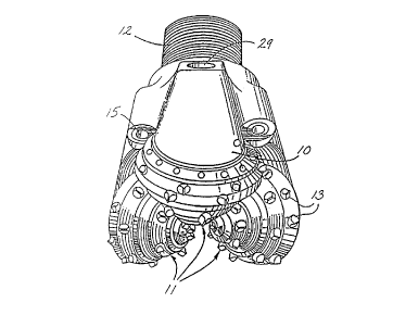
2 5 Brief Des~, ;ption of the Drawin~
A rock bit con~ g an O-ring seal constructed according to the principles of thisinvention is illustrated in semi-schem~tic perspective in FIG. 1 and in partial cross-section
in FIG. 2.
3 0 Detailed Description
A rock bit employing an O-ring seal constructed according to principles of this
invention comprises a body 10 having three cutter cones 11 mounted on its lower end, as
shown in FIG. 1. A threaded pin 12 is at the upper end of the body for assembly of the rock
bit onto a drill string for drilling oil wells or the like. A plurality of tungsten carbide inserts
3 5 13 are pressed into holes in the surfaces of the cutter cones for bearing on the rock formation
being drilled. Nozzles lS in the bit body introduce drilling mud into the space around the
cutter cones for cooling and carrying away formation chips drilled by the bit.
214411~
O-ring seals are generally thought of as comprising a cylin~ric~l inside ~ meter~
outside ~ metpr~ and a cylindrical cross section. Accordingly, for purposes of reference and
clarity, the figures used to describe the principles and embodiments of this invention have
been created to illustrate an O-ring seal having a generally circular cross section. However,
5 the principles of this invention are also meant to apply to O-ring seals having non-cylindrical
cross sections, such as an elliptical cross section and the like. Therefore, it is to be
understood that the principles of this invention may apply to O-rings having a circular or
non-circular cross sections.
FIG. 2 is a fr~gment~ry, longitll-lin~l cross-section of the rock bit, extending radially
10 from the rotational axis 14 of the rock bit through one of the three legs on which the cutter
cones 11 are mounted. Each leg includes a journal pin e~ten(ling downwardly and radially,
inwardly on the rock bit body. The journal pin includes a cylin-lriç~l bearing surface having
a hard metal insert 17 on a lower portion of the journal pin. The hard metal insert is
typically a cobalt or iron-based alloy welded in place in a groove on the journal leg and
15 having a subst~nti~lly greater hardness that the steel forming the joumal pin and rock bit
body.
An open groove 18 is provided on the upper portion of the journal pin. Such a groove
may, for example, extend around 60 percent or so of the circumference of the journal pin,
and the hard metal insert 17 can extend around the rem~ining 40 percent or so. The journal
20 pin also has a cylindric~l nose 19 at its lower end.
Each cutter cone 11 is in the form of a hollow, generally-conical steel body having
cemented h~ng~ten carbide inserts 13 pressed into holes on the external surface. For long
life, the inserts may be tipped with a polycrystalline diamond layer. Such tungsten carbide
inserts provide the drilling action by eng~ging a subterranean rock formation as the rock bit
2 5 is rotated. Some types of bits have hard-faced steel teeth milled on the outside of the cone
instead of carbide inserts.
The cavity in the cone contains a cylin-1ric~l bearing surface including an alunlinllm
bron~ insert 21 deposited in a groove in the steel of the cone or as a floating insert in a
groove in the cone. The ~lumimlm bronze insert 21 in the cone engages the hard metal insert
3 0 17 on the leg and provides the main bearing surface for the cone on the bit body. A nose
button 22 is between the end of the cavity in the cone and the nose 19 and carries the
principal thrust loads of the cone on the journal pin. A bushing 23 surrounds the nose and
provides additional bearing surface between the cone and journal pin. Other types of bits,
particularly for higher rotational speed applications, have roller bearings instead of the
35 exemplary journal b~rings illllstr~t~d herein. It is to be understood that an O-ring seal
constructed according to principles of this invention may be used with rock bits comprising
either roller bearings or conventional journal bearings.
21~116
A plurality of bearing balls 24 are fitted into complementary ball races in the cone and
on the journal pin. These balls are inserted through a ball passage 26, which extends through
the journal pin between the bearing races and the exterior of the rock bit. A cone is first
fitted on the joumal pin, and then the bearing balls 24 are inserted through the ball passage.
5 The balls carry any thrust loads tending to remove the cone from the journal pin and thereby
retain the cone on the journal pin. The balls are retained in the races by a ball retainer 27
inserted through the ball passage 26 after the balls are in place. A plug 28 is then welded
into the end of the ball passage to keep the ball retainer in place. The bearing surfaces
between the journal pin and the cone are lubricated by a grease. Preferably, the interior of
o the rock bit is ev~cu~ted, and grease is introduced through a fill passage (not shown). The
grease thus fills the regions adjacent the bearing surfaces plus various passages and a grease
reservoir, and air is essenti~lly excluded from the interior of the rock bit. The grease
reservoir comprises a cavity 29 in the rock bit body, which is connected to the ball passage
26 by a lubricant passage 31. Grease also fills the portion of the ball passage adjacent the
15 ball retainer, the open groove 18 on the upper side of the journal pin, and a diagonally
exte~ling passage 32 therebetween. Grease is retained in the bearing structure by a resilient
seal in the form of an O-ring 33 between the cone and journal pin. Preferably, the O-ring
is in a slightly V-shaped groove.
A ~les~ule COl~-pellSatiOn S~lb~sembly iS included in the grease reservoir 29. The
2 o sub~sembly comprises a metal cup 34 with an opening 36 at its inner end. A flexible rubber
bellows 37 extends into the cup from its outer end. The bellows is held into place by a cap
38 with a vent passage 39. The pressure compensation subassembly is held in the grease
reservoir by a snap ring 41.
When the rock bit is filled with grease, the bearings, the groove 18 on the journal pin,
25 passages in the journal pin, the lubrication passage 31, and the grease reservoir on the
outside of the bellows 37 are filled with grease. If the volume of grease expands due to
heating, for example, the bellows 37 is compressed to provide additional volume in the sealed
grease system, thereby preventing accumulation of excessive pressures. High pressure in the
grease system can damage the O-ring seal 33 and permit drilling mud or the like to enter the
3 0 bearings. Such m~teri~l is abrasive and can quickly damage the be~rings. Conversely, if
the grease volume should contract, the bellows can expand to prevent low pressures in the
sealed grease system, which could cause flow of abrasive and/or corrosive substances past
the O-ring seal.
The bellows has a boss 42 at its inner end which can seat against the cap 38 at one end
35 of the displacement of the bellows for sealing the vent passage 39. The end of the bellows
can also seat against the cup 34 at the other end of its stroke, thereby sealing the opening 36.
If desired, a pl~s~re relief check valve can also be provided in the grease reservoir for
relieving over-pressures in the grease system that could damage the O-ring seal. Even with
2 1 44 1 1 6
pressure compensator, it is believed that occasional differential pressures may exist across
the O-ring of up to + 150 psi (548 kilopascals).
To m~int~in the desired properties of the O-ring seal at the pressure and temperature
conditions that prevail in a rock bit, to inhibit "pumping" of the grease through the O-ring
seal, and for a long useful life, it is important that the O-ring seal be resistant to crude
gasoline and other chemical compositions found within oil wells, have a high heat and
abrasion resistance, have low rubbing friction, and not be readily deformed under the
pressure and temperature conditions in a well which could allow leakage of the grease from
within the bit or drilling mud into the bit.
o Therefore, it is desired that the O-ring seal have a modulus of elasticity at 100 percent
elongation of from 850 to 1275 psi (6 to 9 megapascals), a minimum tensile strength of 2300
psi (16 megapascals), elongation of from 200 to 350 percent, die C tear strength of at least
250 lb/in. (4.5 kilogram/millimeter), durometer hardness Shore A in the range of from 75
to 85, and a compression set after 70 hours at 100~C of less than about 18 percent and
preferably less than about 16 percent.
A variety of O-rings seals have been employed in such rock bits. Such O-rings
typically comprise acrylonitrile polymers or acrylonitrile/butadiene copolymers. Other
components in the polymers are activators or accelerators for the curing, such as stearic acid,
and agents that add to heat resistance of the polymer, such as zinc oxide and curing agents.
However, these synthetic rubbers typically exhibit poor heat resistance and become brittle
at elevated temperatures after extended periods of time. Additionally, such compounds often
exhibit undesirably low tensile strength and high coefficients of friction. Such properties are
undesirable for a seal in a rock bit, since the high operating temperatures of the bit result in
frequent failure of the seal.
2s Preferred O-ring seals can be formed from the group of elastomeric compositions
including fluoroelastomers, carboxylated elastomers such as carboxylated nitriles, and highly
saturated nitrile (HSN) elastomers and the like. A particularly preferred O-ring seal is made
from an HSN resilient elastomer material and is disclosed in ~ ling (~n;~ n application
serLal No. 2,096,3~0 filed May 14, 1993 that is assigned to the same assignee asthe present invention. An exemplary elastomeric composition may comprise per 100parts by weight of highly-saturated nitrile elastomer, furnace black in the range of from 40
to 70 parts by weight, peroxide curing agent in the range of from 7 to 10 parts by weight,
graphite in the range of from 10 to 20 parts by weight, zinc oxide or magnesium oxide in
the range of from 4 to 7 parts by weight, stearic acid in the range of from 0.5 to 2 parts by
weight, and plasticizer up to about 10 parts by weight.
A mechanism of failure in a rock bit O-ring may be characterized as stick-slip. As
the elastomer of the O-ring moves along the metal surface of the leg or cone, the O-ring
material momentarily sticks to the metal surface. Almost instantly the elastomer then slips
~,
'~1 lgll~
relative to the metal. The 0-ring slips because the rotational force of the O-ring is sufficient
to overcome the break-off friction between the adjacent sealing surfaces. This making and
breaking of bonds between the elastomer and metal dissipates energy and causes frictional
heating. Furthermore, if too strong a bond is formed between the elastomer and metal, some
5 of the elastomer may be removed from the 0-ring, thereby degrading the surface.
It is therefore desirable to minimi7~ the amount of sticking between the elastomer and
metal. Such sticking is minimi7Pd in practice of this invention by modifying the surface of
the 0-ring without ch~n~ing the bulk properties of the main body of the O-ring in such a
manner as to reduce the break-off friction and increase the lubricity and wettablity of the 0-
0 ring seal s--rf~ce
In elastomeric m~teri~l~ the tensile modulus of the elastomer, its tear strength and
hardness are positively correlated. When the hardness of the elastomer is increased, one
normally finds that the modulus and tear strength are also increased. Hardness is therefore
a convenient means for comparing the plop~,lies of elastomers. For a rock bit 0-ring, it is
desirable that the durometer hardness of the 0-ring is in the range of from about 75 to 85
on the Shore A scale. Typically, the hardness of the 0-ring is about 80 Shore A. A
hardness as high as 85 may result in pl~l"alure failure of an 0-ring at the same squeeze.
Typically, in a rock bit, the squeeze of the 0-ring in the seal is from about 7.5 to lO.5
percent, preferably toward the high end of the range for reliable sealing. It is desirable to
20 m~int~in a squeeze in about this range and a bulk hardness in the order of 78 to 83, but to
also increase the surface hardness and hence modulus and tear strength.
A way of modifying the surface p,~"ies of the 0-ring without changing the bulk
plope~lies of the body of the 0-ring is to plasma treat the surface with an inert gas containing
a reactive gas species such as chlorine or fluorine. The chlorinated or fluorinated nitrile
25 rubber modules which form at the surface of the 0-ring due to such tre~tment modify or
change the surface of the O-ring by increasing its lubricity and/or by decreasing its break-off
friction. Additionally, the modified surface may also have a hardness different than that of
the elastomeric body. The modified prope,lies of the 0-ring surface tends to reduce the
occurrence of stick-slip and any m~teri~l loss as a consequence of stick-slip. While not
30 wishing to be bound by any particular theory or m~ch~ni~m, it is believed that the
fluorination of the surface causes reduced break-off friction and reduced occurrences of stick-
slip due to çnh~nced lubricity and wettablity charactçri~tics, minimi~ing the "sticking" portion
of the stick-slip phenomenon.
It is also believed that the reduced occurrence of stick-slip may be caused by
35 enhancing the thermal resi~t~nce of the modified 0-ring surface. The m~t~ri~l~ that are used
to treat the surface of 0-ring have an enhanced thermal resistance when compared to the
elastomeric 0-ring body. This enhanced thermal resistance is believed to reduce the sticking
~ 44 116
portion of the stick-slip phenomena at the O-ring surface and, therefore, serves to reduce the
amount m~teri~l loss and degradation at the O-ring surface.
The properties of the surface may also be changed by grafting a different molecule to
the nitrile molecules adjacent to the surface of the O-ring. Preferably molecules adjacent to
5 the surface are copolymPri7e~ with a fluoropolymer. Other polymers that may be suitable
include polyethylene, silicones and polyu.e~ nP~.
Such potential copolymers are grafted to the nitrile polymer by high energy plasma
tre~tmPnt A high energy plasma comprises a highly ionized and accelerated gas, typically,
an inert gas such as argon, nillogen or the like. Other gaseous species such as a
10 fluorocarbon polymer may be introduced into such a plasma. When such highly energetic
polymers encounter the elastomeric nitrile rubber, bonds in the nitrile and in the fluorocarbon
or the like may be disrupted, thus, providing an opp~llul ily for molecularly bonding the
fluorocarbon to the nitrile substrate. This, of course, changes the surface properties of the
O-ring without ch~nging its bulk plo~llies.
15 - A graft polymer may also be formed on the surface of an O-ring by a variation of this
process. A polymer may be applied to the surface by dipping, spraying or the like.
Thereafter, the surface is subjected to plasma tre~tment and the energetic plasma disrupts
both nitrile and non-nitrile polymers leading to molecular bonding therebetween.One may also increase the surface hardness of the elastomeric nitrile rubber by
2 o tre~tment with sulfur. It is believed that nitrile rubber continues to cure or cross-link during
elevated temperature service even though the nitrile is nominally completely cured. Elevated
lell,peldtures increase hardness of nitrile as well as other rubbers and this may be due to
increased cross-linking. Sulfur tends to promote cross-linking of rubber and treatment of the
nitrile surface with sulfur may enhance cross-linking and hardness adjacent to the surface of
25 the O-ring. Such sulfur tre~tment may be by energetic sulfur introduced into an inert gas
plasma.
An alternative method used to modify the surface of the O-ring is to deposit a few
microns of tungsten disulfide onto the surface of the elastomer by the dip process and
subsequently drying the O-ring in an oven. This surface modification technique, like that
3 0 previously discussed above, also enhances the surface properties of the O-ring, lowers break-
off friction and, thus reduces the tendency for stick-slip.
When the surface pr~ellies of the O-ring are modified in this manner the O-ring
continues to provide a seal for the grease since the bulk pr~ellies of the O-ring are
unchanged and the effect of squeeze is unchanged. The modified surface properties,
35 however, tend to reduce break-off friction, minimi7e stick-slip and minimi7e m~teri~l loss
at the O-ring surface.
2 1 ~ 6
A carboxylated elastomeric nitrile polymer may be prefelled. The carboxylated
polymer appea~s to have improved pr~ellies for a rock bit O-ring as compared with other
HSN rubber, including resistance to hardening with age at elevated telllpelature.
An O-ring seal relies upon the lubricant within the rock bit for lubrication. During
5 normal use of a rock bit, it has been discovered that O-ring seals made from the elastomeric
composition have an average life of approximately 25 to 30 hours at a squeeze of about lO.S
percent when the cutter cones are operated at approximately 375 rpm. The average life of
the elastomeric O-ring seal is limited by frictional heat that occurs at the O-ring surface and
the mat~ri~l loss related to stick-slip caused by the interaction between the adjacent cone and
lo the journal surfaces. As the cone rotates on the journal and along the surface of the O-ring,
the frictional heat generated at the interacting O-ring surface causes the seal matPri~l to
degrade. Ultimately, the degradation of the O-ring seal either permits the grease within the
rock bit to escape or permits the entrance of abrasive drilling mud or the like into the cone.
The occurrence of either of the above conditions is sufficient to cause the rock bit bearings
lS to fail, ending the useful life of the rock bit.
It has been discovered that an O-ring comprising the elastomeric composition can be
constructed in such a manner that it provides a lower coefficient of friction at the surface of
the seal and, thus results in a lower degree of m~tPri~l loss than O-ring seals made entirely
from the elastomeric composition alone. An O-ring seal constructed according to principles
2 o of this invention having a lower coefficient of friction minimi7~s the amount of frictional heat
generated between the cone and the journal and stick-slip, a known cause of rock bit failure.
An embodiment of an O-ring seal constructed according to principles of this invention
comprises a body formed from an elastomeric composition such as one selected from the
group of elastomeric matPrialc previously described, and an enhanced surface enclosing the
25 body formed from a uniform layer of m~teri~l having a different molecular makeup than the
body. A plefell~d m~tPri~l may be selected from the group of metal sulfides including
t~-ng~tçn disulfide (WS2) and molybdenum disulfide (MoS2) and the like. A particularly
preferred surface enhancing m~tPri~l is tungsten disulfide. The m~ter1~1 used to enhance the
prop~l lies of the surface can be applied using well known surface deposition techniques such
30 as by chemical dipping, vapor deposition or the like. However, to afford enhanced
propellies of reduced break-off friction to the surface of the O-ring seal without substantially
increasing the ~limPn~inn of the seal, it is desired that the m~tPri~l used to enhance the
surface actually molecularly bond with or impregnate the structure of the substrate O-ring
body. Techniques for impregn~ting or molecularly bonding such materials to the surface of
35 a substrate are relatively new and are not well known in the art. A preferred technique for
impregnating or molecularly bonding the material to the body of the O-ring seal is by
chemical dipping, wherein the O-ring seal is emersed or dipped into a liquid solution of
surface enhancing m~t~ri~l and then allowed to air dry, such as that conducted by Diversified
_g_
2t4ql~
Drilube, Inc., of Tulsa, Oklahoma under a process that it refers to as the Ultralube process.
During the chemical dipping deposition technique, the l~mell~r crystal structure of the
h~ngctPn (liclllfide dry lubricant is believed to impregnate and molecularly fuse with the
surface portion of the substrate O-ring body without the use of heat, resins, or any other
binders. The molecular interlock established between the seal body and the enhancing
m~teri~l layer is so complete that only removal of the elastomeric m~tPri~l of the seal body
itself can affect the enhanced properties of the modified O-ring surface.
Accordingly, a prerelred O-ring seal comprises a body formed from an elastomericcomposition and a surface formed from a uniform layer of material that encloses and
molecularly bonds with the body via the deposition technique described above. The
technique of molecularly fusing the enhancing m~tPri~l onto the body permits the formation
of a strongly adhered and durable thin film that provides the desired degree of surface
enhancement without having to use multiple layers.
The ability to achieve a surface layer having the desired enhanced properties using
only a thin film of m~tçri~l elimin~tes potential complications that may develop when fitting
together parts having close spatial tolerances. Accordingly, the use of a molecularly bonded
m~teri~l layer elimin~tP~s the need to reconfigure existing O-ring seals to accommodate the
surface layer thickness and, therefore is economically desirable. A preferred surface layer
may have a thickness in the range of from 100 to 500 Angstroms (A).
2 o An O-ring seal constructed according to the above described principles has been shown
to display decreased break-off friction, increased lubricity and wettablity, and increased
thermal resistance at the surface of the O-ring as compared with O-rings constructed entirely
from the elastomeric material alone. These enhanced properties have been shown to enhance
the service life of the O-ring and, thus the service life of a rock bit incorporating the same
by as much as two times. An additional advantage of constructing an O-ring according to
such principles is that, while the surface of the O-ring displays improved properties of
reduced break-off friction and the like, the body of the O-ring formed from the elastomeric
composition retains all of the desired physical properties, such as the desired modulus of
el~cticity, tensile strength, elongation, tear strength, durometer hardness and a low
con-~re~sion set. A further advantage, as mentioned above, is that the overall ~imencinn of
the O-ring seal remains subst~nti~lly the same, elimin~ting potential spatial tolerance
complications as well as pell,litling the use of exi~ting O-ring seals.
~ltern~tively, the surface of the O-ring seal may comprise a uniform layer of m~teri~l
that encloses and is molecularly bonded to the body. The material may be selected from the
group of polymeric m~tPri~lc including fluoropolymers, polyethylene polymers, silicone
polymers, urethane polymers and the like. A particularly preferred m~teri~l is
polytetrafluoroethylene (Pl FE). The surface enhancing material can be applied to the body
of the O-ring seal by using previously described deposition techniques such as chemical dip,
--10--
~44116
chemical vapor deposition and the like. However, it is desired that the m~tçri~l be part of
the intermolecular m~k~up of the surface portion of the O-ring body, thereby providing
enhanced properties of reduced break-off friction, increased lubricity and wettablity, and
increased thermal resi~t~nce at the O-ring surface without significant layer thickness.
Additionally, a layer of surface enh~ncing m~teri~l that is molecularly bonded to the surface
of the O-ring seal will not flake away like a surface layer that is merely coated onto the
substrate surface.
A preferred method for applying and molecularly fusing the alternative surface
enhancing m~teri~l to the O-ring body is by plasma polymerization, which occurs in a
0 polymerization chamber under a vacuum environment, using various gas phase monomers
and catalyst. The O-ring seal is placed into the chamber where gas phase monomers are
introduced and ionized by using a radio frequency energy field, causing the monomers to
break apart to form ions and free electrons. It is believed that some of the ions bombard the
surface of the O-ring seal body, removing some portions of the molecules along the surface.
Other ions are believed to recombined with each other and attach themselves to the surface
of the O-ring seal at the site where the O-ring seal surface molecules have been disrupted or
removed, replacing the surface molecules and forming a new polymeric surface layer
comprising the desired surface çnh~nçing m~teri~l The process of ion recombination and
~tt~t hmçnt to the O-ring seal body continues until a desired layer thickness of the plasma
2 0 polymPri7Pd film is achieved. Plasma polymeri7~tion forms a thin film of the desired surface
enhancing m~t~ri~l that is molecularly bonded or grafted to the O-ring body substrate
m~teri~l that will not flake off or leach out after being applied.
The thickness of the surface layer can be controlled by varying the conditions of the
plasma polymerization and may range between 25 and 1000 A. A preferred O-ring seal
comprises a surface layer having a thickness in the range of 100 to 500 A. Like the use of
the chemical dipping deposition technique previously described, the use of the plasma
polymeri_ation process to molecularly graft a desired surface enhancing material into the
body of the O-ring body permits the formation of an extremely strong thin-film layer which
does not noticeably alter the overall dimensions of the O-ring seal.
A particularly preferred plasma polymeri7~tion process is one conducted by Metro-
Line Industries, Inc. of Corona, California, using a three stage gas plasma surface
modification process. First, the surface of the O-ring body undergoes an atomic cle~ning
process to remove all organic cont~min~nt~, leaving an atomically clean body. Second, the
chemical structure of the surface of the O-ring body is molecularly modified by ion
3 5 bombardment at a high rate of speed during the ionization cycle of the plasma polymeri_ation
process. During ion bombardment the ions impact the surface of the O-ring seal body,
causing the polymer backbone to fracture. Some of the charged molecules then attached
themselves to the surface of the O-ring body, forming a new chemical structure. Finally,
214A116
some of the ions recombine to form the desired polymeric surface enhancing material, e.g.,
PTFE, during the plasma polymerization process and molecularly graft with the molecularly
modified surface of the O-ring seal body, forming an entirely new surface comprising the
desired surface enhancing polymer.
O-ring seals constructed according to the above described principles of this invention
have been shown to display reduced break-off friction, increased lubricity, and increased
thermal resistance at the O-ring surface as compared with O-rings constructed entirely from
only the elastomeric composition. The modified surface layer displays an increased lubricity
due to an enhanced wettablity of the new modified surface. The ability of the modified
0 surface to wet or attract and retain a fluid, e.g., the rock bit lubricant, maximizes the
lubricated interface between the O-ring seal and cone and, thus reduces frictional heat and
break-off friction, minimi~ing stick-slip between adjacent sealing surfaces and extending the
service life of the O-ring and rock bit.
It is to be understood that an O-ring seal may be constructed differently than
specifically described above and not depart from the scope of this invention. For example,
an O-ring seal may be constructed having a layer of surface enhancing m~eri~l molecularly
bonded, to only a portion of the O-ring seal body, i.e., that portion of the O-ring body that
is subjected to stick-slip, and therefore m~tPri~l loss. In this embo~imP-nt, the surface
enhancing m~teri~l would not completely encapsulate the entire O-ring body.
Laboratory tests have been conducted co~p~-;n~ various physical characteristics of
improved O-ring seals constructed according to principles of this invention with O-ring seals
formed from only an elastomeric composition comprising HSN. Table l shows a series of
test results comparing the physical characteristics of an O-ring seal formed entirely from the
HSN material (Standard equals an average of the test results from nine tests) with those of
O-ring seals each comprising a body formed from the HSN elastomeric material and an
enhanced surface layer formed from a molecularly bonded surface enhancing material
previously described (Tests l through 5). The O-rings tested were those typically used in
12 l/4 inch rock bits, having an inside diameter (ID) of approximately 2.9 inches (73
millimeters), a cross section of approximately 0.3 inches (7.6 millimeters), and an outside
3 0 diameter (OD) of approximately 3.5 inches (89 millimeters). All of the tests were conducted
under similar conditions of cone revolution (375 rpm) and percent squeeze (approximately
10.6 percent).
- --12--
2~4116
TABLE 1
SEAL WEAR TEST RESULTS
Tr 6t N ~ t t
Rock B;t Size (inches) 12 1 /4 12 1 /4 12 1 /4 12 1 /4 12 1 /4 12 1 /4
O-Rin~ Size (OD-inches) 3.5 3.5 3.5 3.5 3.5 3.5
Speed, rpm 375 375 375 375 375 375
0 O-Rin~ Material HSN HSN HSN HSN HSN HSN
Coatin~ ~ WS2 WS2 WS2 PTFE PTFE
Life 27.4 64 49 58 42 49
Time To Smooth (hours) - - - 20 3.5 33
Durometer (Shore A) 83 85 85 85 82 81
Percent Squeeze 10.6 10.6 10.8 10.5 10.9 10.6
Surface Finish (Ra) 20 32 26 25 21 15
Ave. Le~ Temp. (F) 270 296 263 227 234 328
Ave. Cone Temp. (Fl 227 222 229 N/A 206 216
Ave. Torque (in-lbs) 222 266 397 339 143 235
2 5 Max. Le~ Temp. (F) 397 494 494 347 500 Plus 491
Msx. Cone Temp. (F) 306 324 436 N/A 308 391
Max. Torque (in-lbs) 559 534 867 492 734 505
As shown in Table 1, the average life for an O-ring seal formed entirely from the
HSN elastomeric m~tçri~l subjected to a cutter cone speed of approximately 375 rpm is 27.4
hours (Standard). Test number 1 is an example of a first embodiment of an improved O-ring
seal comprising a body formed from the HSN elastomeric m~t~ri~l and a surface layer of
molecularly bonded tungsten ~ lfide applied via the dip process. Test 1 displayed a service
life of approximately 64 hours, approximately 2.3 times greater than the O-ring seal
comprising HSN alone. Test numbers 2 and 3 are identical examples of a first embodiment
of an improved O-ring, each displaying a service life of approximately 49 hours and 58
hours, respectively. Accordingly, the average service life for a first embodiment of an
O-ring seal comprising an enhanced surface layer of molecularly bonded tungsten disulfide,
--13--
2144116
as represented in Tests 1, 2, and 3 is approximately 57 or 2 times the service life of the
O-ring seal formed entirely from the HSN elastomeric composition.
Tests 4 and 5 are of a first embodiment of an improved O-ring seal comprising a body
formed from the HSN elastomeric m~tt~ri~l and a surface layer with molecularly bonded
5 PI~FE applied via the plasma polymPri7~tion process. Tests 4 and 5 registered service lives
of 42 and 49 hours, respectively. Accordingly, the average service life for first embodiment
of the O-ring seal, comprising an enhanced surface layer of molecularly bonded PTFE, is
approxim~tPly 45.5 hours or 1.7 times the service life of the O-ring seal formed entirely
from the HSN elastomeric composition.
lo These results of these tests illustrate the enhanced surface properties of an improved
O-ring seal constructed according to principles of this invention and the effect that such
enhanced surface properties have in extending the service life of a rock bit by two times, and
in some cases more than that, over O-ring seals formed from the HSN elastomeric material
alone.
Although, limited embodiments of an improved O-ring seal for rock bit bearings have
been described and illustrated herein. Many modifications and variations will be apparent
to those skilled in the art. Accordingly, it is to be understood that within the scope of the
appended claims, the improved O-ring seal for rock bit bearing according to principles of this
invention may be embodied other than as specifically described herein.
--14--