Language selection

Search

Patent 2144153 Summary

Third-party information liability

Some of the information on this Web page has been provided by external sources. The Government of Canada is not responsible for the accuracy, reliability or currency of the information supplied by external sources. Users wishing to rely upon this information should consult directly with the source of the information. Content provided by external sources is not subject to official languages, privacy and accessibility requirements.

Claims and Abstract availability

Any discrepancies in the text and image of the Claims and Abstract are due to differing posting times. Text of the Claims and Abstract are posted:

  • At the time the application is open to public inspection;
  • At the time of issue of the patent (grant).
(12) Patent: (11) CA 2144153
(54) English Title: METHOD FOR FIXING AN ENERGY STORING FLYWHEEL WITH PRE-TENSION ON A SUPPORT AND UNIT COMPRISING AN ENERGY STORING WHEEL
(54) French Title: METHODE DE MISE EN PLACE D'UN VOLANT DE STOCKAGE D'ENERGIE A TENSION PREALABLE SUR UN SUPPORT ET DISPOSITIF MUNI D'UN VOLANT DE STOCKAGE D'ENERGIE
Status: Deemed expired
Bibliographic Data
(51) International Patent Classification (IPC):
  • F16F 15/30 (2006.01)
  • F16D 1/08 (2006.01)
  • F16D 1/091 (2006.01)
  • F16D 1/096 (2006.01)
  • F16F 15/315 (2006.01)
(72) Inventors :
  • THOOLEN, FRANCISCUS JOHAN MARIE (Netherlands (Kingdom of the))
(73) Owners :
  • CCM BEHEER B.V. (Netherlands (Kingdom of the))
(71) Applicants :
(74) Agent: GOWLING WLG (CANADA) LLP
(74) Associate agent:
(45) Issued: 1998-07-28
(86) PCT Filing Date: 1993-09-03
(87) Open to Public Inspection: 1994-03-31
Examination requested: 1995-03-08
Availability of licence: N/A
(25) Language of filing: English

Patent Cooperation Treaty (PCT): Yes
(86) PCT Filing Number: PCT/NL1993/000180
(87) International Publication Number: WO1994/007053
(85) National Entry: 1995-03-08

(30) Application Priority Data:
Application No. Country/Territory Date
9201584 Netherlands (Kingdom of the) 1992-09-11

Abstracts

English Abstract


Method for applying an energy-storing flywheel (2) with pre-tension with an inner bore on a coaxial support (16) rotating
symmetrically with the latter and having a tapering outer surface, in which a ring (22a, 22b, 22c, 22d) is placed in the flywheel
bore with a tapering inner surface, of which the taper corresponds with that of the support (16) and the entire unit thus obtained
is shifted on the support (16) until the desired pre-tension is obtained. In accordance with the invention both the inner bore of the
flywheel (18a, 18b, 18c, 18d) and the outer surface of the ring (22a, 22b, 22c, 22d), which co-operate, have a design with a
corresponding taper. Furthermore, the invention includes a clamping ring (22a), which can be used when using this method, having a
tapering inner surface, the outer surface, intended for functioning with the flywheel being also conical.


French Abstract

Méthode de fixation d'un volant (2) servant à emmagasiner l'énergie au moyen d'une tension préalable, qui est muni d'un alésage intérieur sur un support coaxial (16) tournant de manière symétrique avec ce dernier et comportant une surface extérieure conique dans laquelle une bague (22a, 22b, 22c, 22d) est placée dans l'alésage du volant ayant une surface intérieure conique, dont la conicité correspond à celle du support (16); l'unité complète ainsi constituée est déplacée sur le support (16) jusqu'à ce que la tension préalable voulue soit obtenue. D'après la présente invention, l'alésage intérieur du volant (18a, 8b, 18c, 18d) comme la surface extérieure de la bague (22a, 22b, 22c, 22d), qui coopèrent, sont conçus pour avoir des parties coniques correspondantes. De plus, l'invention comprend une bague de serrage (22a) pouvant être utilisée en même temps que cette méthode, cette bague possède une surface conique intérieure, et sa surface extérieure qui doit coopérer avec le volant est également conique.

Claims

Note: Claims are shown in the official language in which they were submitted.

CLAIMS

1. Method for fixing an energy-storing flywheel with pre-tension with
an inner bore on a coaxial support rotating symmetrically with the latter and
having a tapering outer surface, in which a ring is placed in the flywheel bore
said ring having a tapering inner surface of which the taper corresponds with
that of the support and the entire unit thus obtained is shifted on the support
until the desired pre-tension is obtained, characterized in that both the inner
bore of the flywheel and the outer surface of the ring, which co-operate, has
been designed with a corresponding taper.

2. Method according to claim 1, characterized in that the ring is
applied using a thermal shrinking connection process.

3. Method according to claim 1 or 2, characterized in that the outer
surface of the support is coated with a thin coating of ceramic material
preceding the application of the ring.

4. A unit comprising an energy-storing flywheel having an inner bore,
a coaxial support rotating symmetrically with the flywheel and having a
tapering outer surface, and a prefabricated clamping ring having a tapering
inner surface corresponding to the tapering outer surface of the support, the
clamping ring being in engagement with the inner bore of the flywheel and the
tapering outer surface of the support, characterized in that the outer surface
of the clamping ring has also an increasing conical design which corresponds
to an accordingly decreasing conical design of the inner bore of the flywheel.

5. A unit according to claim 4 characterized in that the inner and
outer surface of the clamping ring thereof are tapered in the same direction.

6. A unit according to claim 5, characterized in that the degree of
taper of the inner and outer surface is the same.

7. A unit according to any one of claims 4-6, characterized in that
the degree of taper lies between 1:60 and 1:100.

8. A unit according to any one of claims 4-6, characterized in that
the clamping ring is made of aluminum.

9. A unit according to claim 7, wherein the clamping ring is made of
aluminum.

10. A unit according to claim 7, wherein the degree of taper is equal
to 1:80.

11. A unit according to claim 10, wherein the clamping ring is made
of aluminum.

Description

Note: Descriptions are shown in the official language in which they were submitted.


CA 021441~3 1998-03-03


Method for fixing an energy-storing flywheel with pre-
tension on a support and unit comprising an energy
storing flywheel.

The invention concerns a method for fixing a
composite energy-storing flywheel with pre-tension with
an inner bore on a coaxial support rotating symmetrically
with the latter and having a tapering outer surface, in
which a ring is placed in the flywheel bore, said ring
having a tapering inner surface, of which the taper
corresponds with that of the support and the entire unit
thus obtained is shifted on the support until the desired
pre-tension is obtained.
A similar method is known from EP-B1-0 137 759. The
ring used in this known method has a cylindrical outer
surface, fitting within the cylindrical bore of the
flywheel, and is provided with a number of incisions
running over the greatest part over its length. A
consequence thereof is that the ring is elastically
deformable in a radial direction due to changes in the
widths of the incisions, with which it is intended to
accomplish, that by placing the ring with the tapered
inner bore on the tapered rotating symmetrical support,
the outer surface in contact with the inner bore of the
flywheel deflects outwards, thereby generating radial
compressive stress in the flywheel.
The objection to this known method is that the
presence of the longitudinal incisions, as a result of
changes in their width, results in surface damage to the
flywheel bore, and therefore in stress concentrations
that could have fatal results at a high rotational speed,
while the radial pre-tension attainable with this known
method is still insufficient to avoid delamination of the
flywheel when operating at extremely high rotational or
peripheral velocities respectively in the order of 500-
600 m/s.
The aim of this invention is to overcome thisobjection. In accordance with the invention this aim is
achieved by designing both the inner bore of the flywheel
and the co-operating outer surface of the ring, with a
corresponding taper.

CA 021441~3 1998-03-03


These measures result in an uninterrupted outer
surface of the ring, so that the chance of damage to the
inner bore of the flywheel is nil. Furthermore, a
considerably higher pre-tension can be achieved, which
means that higher flywheel rotational velocities are
possible.
Preferred embodiments of the method in accordance
with the invention are described in claims 2-3, while a
unit comprising an energy-storing flywheel as defined in
the preamble of claim 4 is characterized by the measures
defined in the characterising clause of this claim,
preferred embodiments being subject of claims 5-8.
The invention is elucidated on the hand of the
drawing in which:
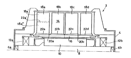
Figure 1 is a longitudinal section through a
flywheel energy storage unit, in which the flywheel parts
have been fixed according to the method of the invention;
Figure 2 is a partial section on an enlarged scale
of an energy-storing flywheel part, in combination with
the used clamping ring in accordance with the invention;
Figure 3 explains the use of this clamping ring in
combination with the flywheel part in a drawing which is
not to scale.
Figure 1 schematically shows a flywheel energy
storage unit in its entirety indicated by reference
numeral 2, containing a housing 4, with in it a stator 8
with stator windings 10, supported by suitable supports
6a and 6b. By means of sultable bearings 12a and 12b
stator 8 bears a rotor 14, which consists of a rotor bush
16 and the disc-shaped flywheel parts 18a-18d, which are
fixed on the rotor bush. Each of these flywheel discs
has a wound and therefore stratified structure, as for
example known from EP-A- 0 137 759.
During operation radially outward forces will occur
in the respective flywheel parts, as a result of which
delamination will occur when a certain limit value of the
number of revolutions is exceeded. This limit value is

2144153
W094/070~3 PCT/NL93/00180


increased by applying radial compression stresses via the
conically clamped joints. In accordance with the invention
these compression stresses are generated and the rotat-.onal
velocity limit value is considerably increased by using a
specially formed clamping ring in combination with a
special configuration of the inner surface of each rotor
part 18a-18d and the outer surface of rotor bush 16. As
figure 2 in particular shows, the outer surface 20 of the
preferably steel rotor bush is tapered, in such a way that
this surface 20 encloses with line 22, which is parallel to
the rotor bush centre line 24, an angle ~, in such a way
that the diameter of the outer surface part 20a of rotor
bush 16 increases from left to right up to half of the
length of the rotor bush, after which the diameter
decreases again with.the same degree of taper. Now in
accordance with the invention clamping rings 22a-22d are
used between the respective flywheel parts 18a-18d and the
outer surface of rotor bush 16 which have a corresponding
taper with inner surface 24a, which co-operates with the
outer surface of rotor bush 16. In figure 3 this taper has
been drawn in an exaggerated way, and it is also indicated
by angle ~.
In accordance with the invention the outer surface 26a
of clamping ring 22a (preferably made of aluminium) also
has an increasing conical design, indicated in figure 3 by
angle ~. This taper is also present at inner surface 28a of
flywheel part 18a. There the angle between this inner
surface and a line parallel to the flywheel centre line is
also equal to ~. For the sake of clarity these angles,
which in practice are approx. 0.8~ degrees if there is a
proved suitable degree of taper of approx. 1:80, have been
drawn larger in an exaggerated way in figure 3.
For the assembly of flywheel parts 18a-18d on rotor
bush 16, a ring, for example ring 22a, is first pressed on
the matching flywheel part, for example flywheel part 18a,
after which the flywheel part is pressed on the rotor
together with the ring. In this way the correct radial pre-


W O 94/07053 ~ J 3 PC~r/NL93/001~n


tension is obtained if the dimensioning is correct.
Since, as figure 1 shows, the outer surface of rotorbush 16 consists of two parts, 20a and 20b, with a mutually
opposed taper, rotor parts 18b and 18a are applied to the
left on the rotor with their clamping rings 22b and 22a,
while rotor parts 18c and 18d are applied to the right of
the rotor with clamping rings 22c and 22d.
It is within the scope of the invention when the
clamping rings are not only applied between a flywheel part
and the rotor bush, but also between two radially connected
sections of a flywheel part designed with a suitable
configuration, as indicated in figure 4 for flywheel parts
18a' and 18a", with clamping ring 22a', which is marked by
broken lines and situated in between. It is also possible
to combine the use of a clamping ring in accordance with
the invention with the usual thermal contraction. Finally,
the clamping ring can be used for fixing balancing weights.
The wear of the ring on the axle can be prevented by
coating the axle with a thin coating of ceramic material
(not indicated in the figures) preceding the application of
the ring.

Representative Drawing
A single figure which represents the drawing illustrating the invention.
Administrative Status

For a clearer understanding of the status of the application/patent presented on this page, the site Disclaimer , as well as the definitions for Patent , Administrative Status , Maintenance Fee  and Payment History  should be consulted.

Administrative Status

Title Date
Forecasted Issue Date 1998-07-28
(86) PCT Filing Date 1993-09-03
(87) PCT Publication Date 1994-03-31
(85) National Entry 1995-03-08
Examination Requested 1995-03-08
(45) Issued 1998-07-28
Deemed Expired 2012-09-04

Abandonment History

There is no abandonment history.

Payment History

Fee Type Anniversary Year Due Date Amount Paid Paid Date
Application Fee $0.00 1995-03-08
Registration of a document - section 124 $0.00 1995-09-14
Reinstatement: Failure to Pay Application Maintenance Fees $200.00 1995-10-25
Maintenance Fee - Application - New Act 2 1995-09-04 $50.00 1995-10-25
Reinstatement: Failure to Pay Application Maintenance Fees $200.00 1997-05-15
Maintenance Fee - Application - New Act 3 1996-09-03 $50.00 1997-05-15
Maintenance Fee - Application - New Act 4 1997-09-03 $50.00 1997-08-25
Final Fee $150.00 1998-03-03
Maintenance Fee - Patent - New Act 5 1998-09-03 $75.00 1998-08-18
Maintenance Fee - Patent - New Act 6 1999-09-03 $75.00 1999-08-25
Maintenance Fee - Patent - New Act 7 2000-09-04 $75.00 2000-07-24
Maintenance Fee - Patent - New Act 8 2001-09-03 $75.00 2001-08-02
Maintenance Fee - Patent - New Act 9 2002-09-03 $150.00 2002-07-15
Maintenance Fee - Patent - New Act 10 2003-09-03 $200.00 2003-07-30
Maintenance Fee - Patent - New Act 11 2004-09-03 $250.00 2004-08-25
Maintenance Fee - Patent - New Act 12 2005-09-05 $250.00 2005-08-04
Maintenance Fee - Patent - New Act 13 2006-09-05 $250.00 2006-08-31
Expired 2019 - Corrective payment/Section 78.6 $950.00 2007-01-16
Maintenance Fee - Patent - New Act 14 2007-09-04 $250.00 2007-08-30
Maintenance Fee - Patent - New Act 15 2008-09-03 $450.00 2008-07-23
Maintenance Fee - Patent - New Act 16 2009-09-03 $450.00 2009-08-12
Maintenance Fee - Patent - New Act 17 2010-09-03 $450.00 2010-07-27
Owners on Record

Note: Records showing the ownership history in alphabetical order.

Current Owners on Record
CCM BEHEER B.V.
Past Owners on Record
THOOLEN, FRANCISCUS JOHAN MARIE
Past Owners that do not appear in the "Owners on Record" listing will appear in other documentation within the application.
Documents

To view selected files, please enter reCAPTCHA code :


To view images, click a link in the Document Description column. To download the documents, select one or more checkboxes in the first column and then click the "Download Selected in PDF format (Zip Archive)" or the "Download Selected as Single PDF" button.

List of published and non-published patent-specific documents on the CPD .

If you have any difficulty accessing content, you can call the Client Service Centre at 1-866-997-1936 or send them an e-mail at CIPO Client Service Centre.


Document
Description 
Date
(yyyy-mm-dd) 
Number of pages   Size of Image (KB) 
Claims 1998-05-26 2 50
Description 1997-08-04 4 179
Claims 1997-08-04 2 50
Cover Page 1995-07-11 1 18
Description 1998-03-03 4 177
Description 1998-05-26 4 177
Abstract 1994-03-31 1 56
Description 1994-03-31 4 186
Claims 1994-03-31 2 66
Drawings 1994-03-31 2 35
Cover Page 1998-07-20 1 60
Representative Drawing 1998-01-23 1 9
Representative Drawing 1998-07-15 1 8
Fees 1999-08-25 1 30
Fees 2006-08-31 1 30
Fees 2004-08-25 1 33
Fees 1997-08-25 1 34
Fees 2003-07-30 1 32
Prosecution-Amendment 2007-01-16 2 90
Fees 1998-08-18 1 32
Correspondence 1997-12-04 1 104
Correspondence 1998-03-03 3 135
Fees 2000-07-24 1 28
Fees 2001-08-02 1 25
Fees 2002-07-15 1 38
National Entry Request 1995-03-08 4 159
Prosecution Correspondence 1995-03-08 12 523
International Preliminary Examination Report 1995-03-08 13 386
National Entry Request 1995-03-23 2 61
Office Letter 1995-12-14 1 20
Prosecution Correspondence 1995-08-28 1 42
Prosecution Correspondence 1995-10-25 1 31
Fees 1997-05-15 1 41
Fees 2005-08-04 1 30
Correspondence 2007-01-25 1 12
Fees 2007-08-30 1 32
Fees 2008-07-23 1 31
Fees 2009-08-12 1 32
Fees 2010-07-27 1 37
Fees 1995-10-25 1 41