Language selection

Search

Patent 2144353 Summary

Third-party information liability

Some of the information on this Web page has been provided by external sources. The Government of Canada is not responsible for the accuracy, reliability or currency of the information supplied by external sources. Users wishing to rely upon this information should consult directly with the source of the information. Content provided by external sources is not subject to official languages, privacy and accessibility requirements.

Claims and Abstract availability

Any discrepancies in the text and image of the Claims and Abstract are due to differing posting times. Text of the Claims and Abstract are posted:

  • At the time the application is open to public inspection;
  • At the time of issue of the patent (grant).
(12) Patent: (11) CA 2144353
(54) English Title: BONE PLATE
(54) French Title: PLAQUE POUR LA REPARATION DES OS
Status: Deemed expired
Bibliographic Data
(51) International Patent Classification (IPC):
  • A61B 17/80 (2006.01)
(72) Inventors :
  • TEPIC, SLOBODAN (Switzerland)
  • BRESINA, STEPHEN (Switzerland)
(73) Owners :
  • SYNTHES (U.S.A.) (United States of America)
(71) Applicants :
  • SYNTHES (U.S.A.) (United States of America)
(74) Agent: BORDEN LADNER GERVAIS LLP
(74) Associate agent:
(45) Issued: 2001-08-21
(22) Filed Date: 1995-03-10
(41) Open to Public Inspection: 1995-11-25
Examination requested: 1998-08-07
Availability of licence: N/A
(25) Language of filing: English

Patent Cooperation Treaty (PCT): No

(30) Application Priority Data:
Application No. Country/Territory Date
249,238 United States of America 1994-05-24

Abstracts

English Abstract


A bone plate has an upper side, a lower side for bone
contact, two longitudinal sides, a longitudinal center line
and a plurality of screw holes extending from the upper to
the lower side. The surface of the upper side around the
screw holes is designed as a depressed area with regard to
the rest of the upper side and the side edge of the
depressed area is run approximately parallel to the
longitudinal sides. The removal of material is effected at
strategic locations of the bone plate in order to reduce
the peak stresses.


Claims

Note: Claims are shown in the official language in which they were submitted.


CLAIMS
1. Bone plate with an upper side, a lower side for bone
contact, two longitudinal sides, a longitudinal center line,
a plurality of cylindrical screw holes extending from said
upper to said lower side, said screw holes having curved
edges, an area of said upper side around said screw holes
being depressed with respect to the rest of said upper side,
said depressed area having a curved upper edge, the upper
edge of said depressed area having a curvature, C1, which is
less than 60% of the curvature, C2, of the edge of said
screw hole.

2. Bone plate according to claim 1, wherein said
curvature C1 is smaller than 10% of C2.

3. Bone plate according to claim 1, wherein the depth of
said depressed area gradually decreases toward said
longitudinal center line of the bone plate.

4. Bone plate having an upper surface, a lower surface
for bone contact, a longitudinal center line and a plurality
of cylindrical screw holes extending through the plate, said
screw holes having edges, the upper surface of the plate
being dished out in the area around said screw holes to form
elongated cavities, said cavities having side walls
ascending steeply to said upper surface and sloping end
walls tapering less steeply in the longitudinal direction
from the screw holes upwardly to said upper surface, said
upper surface being uninterrupted between said dished-out
areas.

5. Bone plate according to claim 4, wherein the depth of
said cavities gradually decreases toward said longitudinal
center line of the bone plate.

6. Bone plate having an upper surface, a lower surface
for bone contact, a longitudinal center line and a plurality
of screw holes extending through the plate, said screw holes


having edges, the upper surface of the plate being dished
out in the area around said screw holes to form elongated
cavities having side walls and sloping end walls tapering in
the longitudinal direction from the edges of the screw holes
upwardly to said upper surface, said side walls having a
different slope from the slope of said end walls, said upper
surface being uninterrupted between said cavities and
wherein the depth of said cavities decreases towards said
longitudinal center line.
7. Bone plate according to claim 6, wherein the lower
surface of the bone plate has a concave shape.
8. Bone plate according to claim 7, and comprising
transverse cuts on said lower surface of the bone plate.
9. Bone plate according to claim 6, wherein the depth of
said cavities is in the range of 0.2 to 2.0 mm.
10. Bone plate according to claim 6, wherein the distance
from the edge of said screw holes to said side walls is less
than 1 mm.
11. Bone plate according to claim 6, wherein each of a
plurality of screw holes associated with cavities is a
cylindrical screw hole.
12. Bone plate having an upper surface, a lower surface
for bone contact, a longitudinal center line, and a
plurality of screw holes extending through the plate, said
screw holes having edges, the upper surface of the plate
being dished out in the areas around the screw holes to form
elongated cavities having side walls, said side walls having
edges, and sloping end walls tapering in the longitudinal
direction from the edges of the screw holes upwardly to said
upper surface, said upper surface being uninterrupted
between said cavities, the depth of said cavities being such
that the maximum stress under bending at the edges of said


side walls is approximately equal to the maximum stress at
the edges of said screw holes.
13. Bone plate according to claim 12, wherein said side
walls are generally normal to said upper surface.
14. Bone plate according to claim 12, wherein each of a
plurality of screw holes associated with cavities is a
cylindrical screw hole.
15. Bone plate according to claim 12, wherein the depth
of said cavities gradually decreases toward said
longitudinal center line of the bone plate.
16. Bone plate having an upper surface, a lower surface
for bone contact, a longitudinal center line and a plurality
of cylindrical screw holes extending through the plate, said
screw holes having edges, the upper surface of the plate
being dished out in the area around said screw holes to form
elongated cavities, said cavities having side walls
ascending steeply to said upper surface and the cavity
tapers less steeply adjacent its side walls in the
longitudinal direction from the screw holes upwardly to said
upper surface.
17. Bone plate according to claim 16, wherein the depth
of said cavities gradually decreases toward said
longitudinal center line of the bone plate.

Description

Note: Descriptions are shown in the official language in which they were submitted.


BONE PLATE 214 4 3 5 ~


FIELD OF THE INVENTION


This invention relates to a bone plate with an upper side, a
lower side for bone contact, two transverse sides, two
longitudinal sides, a longitudinal center line, a plurality of
screw holes extending from said upper to said lower side, said
surface of said upper side around said screw holes being
designed as a depressed area with regard to the rest of said
upper side.


BACKGROUND ART


Strength reduction caused by stress concentration around screw
holes of the bone plate utilized to lock the implant to the bone
with screws or bolts can lead to failure of the implant. The
conventional approach for improving the strength of the bone
plate is to increase the dimensions of the critical section or
add material around the hole.
The disadvantages of these known modifications are increased
invasiveness of the implant. Furthermore, in the surgical
application for which the bone plates are designed, it is not
always possible to increase the dimensions at the critical

sections of the bone plate.
A minimal amount of tissue disturbance would be desirable.

- 214~35~
SUMMARY OF THE INVENTION


The invention as claimed aims at solving the above described
problems by providing a plate having the same over-all
dimensions with less material. The removal of material is
effected at strategic locations of the bone plate in order to
reduce the peak stresses.


With a beam (approximating the bone plate body) loaded in
bending, the stresses can be reduced at the edge of the screw
holes by bringing the hole closer to the neutral longitudinal
axis of the beam. This is done by removing material from the
surface of said upper side around said screw holes, e.g. by
cutting a continuous or discontinuous longitudinal groove. The
depth of the groove is optimized when the stresses at point A
(edge of the screw hole) and point B (edge of the groove at the
screw hole) are equal.


In a further embodiment of the invention - where transverse cuts
are present on the under surface of the implant - the
cross-section between the screw holes is not decreased.
Therefore, the groove on the top surface is made discontinuous
with smooth transition in and out of the hole.


In a further embodiment of the invention - where the
undersurface of the bone plate has a concave shape - the height
of contact between the screw hole and the bone plate was reduced
along the longitudinal center line of the bone plate with a flat


_ 4 ~1~43s3

groove. Material should not be reduced along the longitudinal
center line of the bone plate. With an optimized profile on a
circular tool, an overcut is produced that permits a smooth
transition into and out of the screw hole; reduces the stress
along the edge of the screw hole; and maintains full contact
height with the screw along the longitudinal center line of the
bone plate.


The various features of novelty which characterize the
invention are pointed out with particularity in the claims
annexed to and forming part of this disclosure. For the better
understanding of the invention, its operating advantages and
specific objects attained by its use, reference should be had to
the accompanying drawings, examples and descriptive matter in
which are illustrated and described preferred embodiments of the
invention.


BRIEF DESCRIPTION OF THE DRAWINGS


In the drawings:


Fig. 1 is a schematic view of a fractured bone held together
with a bone plate;


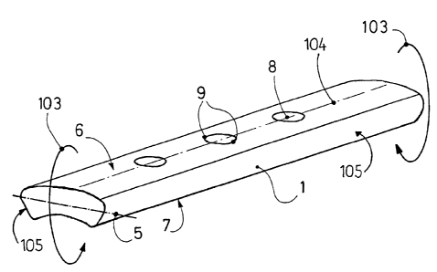
Fig. 2 is a perspective view of a bone plate;

- 2144~53
Fig. 3 is a perspective view of a bone plate with a
longitudinal groove removed;


Fig. 4 is a perspective view of the bone plate according to the
invention with short grooves only in the hole region;


Fig. 5 is a transverse section perpendicular to the longitudinal
axis of the bone plate of Fig. 4 through the center of a screw
hole


Fig. 6 is a transverse section of the bone plate analogous to
Fig. 5 but with a modified groove profile;


Fig. 7 perspective view, including transverse section through a
plate hole with special over-cuts;


Fig. 8 is a lateral view of the bone plate of Fig. 7; and


Fig. 9 is a top view of the bone plate of Fig. 7.


DETAILED DESCRIPTION OF THE INVENTION


Referring to Fig. 1, a conventional bone plate 1 for treatment
of bone fractures 3 is fixed to the bone 2 by means of a number
of screws 4. The bending moment - indicated by arrows 103 -
applied to the bone 2 by muscle forces causes tension on one side
of the bone 2 while the other side is loaded in compression.


6 21413S3

Typically, the plate 1 is applied to the tension side of the bone
2. Therefore, the plate 1 is loaded in either tension or a
combination of bending and tension depending on the amount of
contact between the bone 2 halves at point 100.


The plate 1 shown in Fig. 2 is loaded in bending as indicated by
arrows 103. Longitudinal center line 104 of the plate 1 is shown
on the top surface 6. Longitudinal sides of the plate 1 are
indicated by numerals 105. The highest stresses occur at the
furthest distance in a cross section from the neutral axis 5
which is at the top surface 6 or the bottom surface 7. The holes
8 cause stress concentrations at the edge of the holes 9 which
increase the tensile stress on the upper surface 6 by a factor of
between 2 to 3.


Referring to Fig. 3, the stresses can be reduced at the edge of
the holes 9 by bringing the edge of the hole 9 closer to the
neutral axis 5 of the cross section of the plate. A groove 10
cut into the plate 1 brings the edge of the hole 9 closer to the
neutral axis 5. The depth of the groove is optimized when the
stresses at point 101 (edge of hole 9) and point 102 (edge of
groove 11 at hole) are equal. If the groove is made deeper than
this, the loss in strength due to the decrease of the
cross-sectional area 12 becomes more significant than the gain
made by reducing the stress at the hole edge 9.


7 2144353

Fig. 4 shows an embodiment of the invention in which the plate
has transverse cuts 13 and a longitudinal cut 14 on the lower
surface 7 to reduce contact between the plate and bone. Due to
the transverse undercuts 13, the cross-section 15 between the
holes is already significantly reduced and should not be
decreased further by an additional groove 10 on the upper surface
6 as in the embodiment according to Fig. 3 . Therefore, the
groove on the upper surface 6 is made discontinuous into short
segmental grooves 16 providing a smooth transition into and out
of the holes 8.


As shown if Fig. 5, along the centerline 106 the height of
contact between the screw and the hole 8 is less than the height
17 at the edge of the hole. This could lead to instability of
the screw in the longitudinal axis of the plate. Therefore,
material should not be removed along the longitudinal centerline
of the plate.


With the optimized profile on a circular tool, the cross section
shown in Fig. 6 is created. With this cross section, the height
of contact 18 along the centerline 106 is at least equal to the
height 17 at the edge of the hole.


A further embodiment of the invention is shown in Figs. 7 - 9,
wherein the plate is provided with special overcuts in the form

of depressed areas 19 that permit a smooth transition into and
out of the hole 8 and still reduce the stress along the edge of
the hole 9. The depth of the recessed areas 19 should


8 21~4353

purposefully be in the range of 0.2 to 2.0 mm and are designed
in such a way that maximum stress at remaining surface of said
upper side near said holes is approximately equal to the maximum
stress at edges of said holes within said depressed areas.~


Referring to Fig. 9 curvature C2 of the hole 8 is defined as the
ratio l/r2, where r2 is the radius 20 of the hole 8.
Correspondingly, curvature Cl is equal to the ratio l/rl, where
rl is the radius of the edge 11 of the depressed area 19.
Distance between the edge 11 of the depressed area 19 and the
edge 9 of the hole 8 is indicated by arrows 22 and should
preferably be in the range of 0.1 to 1.0 mm. Curvature Cl should
be smaller than 60%, preferably smaller than 10% of the
curvature C2.


While the foregoing description and drawings represent the
preferred embodiments of the present invention, it will be
obvious for those skilled in the art that various changes and
modifications may be made therein without departing from the
true spirit and scope of the present invention.


Representative Drawing
A single figure which represents the drawing illustrating the invention.
Administrative Status

For a clearer understanding of the status of the application/patent presented on this page, the site Disclaimer , as well as the definitions for Patent , Administrative Status , Maintenance Fee  and Payment History  should be consulted.

Administrative Status

Title Date
Forecasted Issue Date 2001-08-21
(22) Filed 1995-03-10
(41) Open to Public Inspection 1995-11-25
Examination Requested 1998-08-07
(45) Issued 2001-08-21
Deemed Expired 2007-03-12

Abandonment History

There is no abandonment history.

Payment History

Fee Type Anniversary Year Due Date Amount Paid Paid Date
Application Fee $0.00 1995-03-10
Registration of a document - section 124 $0.00 1995-08-31
Maintenance Fee - Application - New Act 2 1997-03-10 $100.00 1997-02-21
Maintenance Fee - Application - New Act 3 1998-03-10 $100.00 1998-02-17
Request for Examination $400.00 1998-08-07
Maintenance Fee - Application - New Act 4 1999-03-10 $100.00 1999-02-26
Maintenance Fee - Application - New Act 5 2000-03-10 $150.00 2000-02-22
Maintenance Fee - Application - New Act 6 2001-03-12 $150.00 2001-02-20
Final Fee $300.00 2001-05-15
Maintenance Fee - Patent - New Act 7 2002-03-11 $150.00 2002-02-18
Maintenance Fee - Patent - New Act 8 2003-03-10 $150.00 2003-02-17
Maintenance Fee - Patent - New Act 9 2004-03-10 $200.00 2004-03-03
Maintenance Fee - Patent - New Act 10 2005-03-10 $250.00 2005-03-04
Owners on Record

Note: Records showing the ownership history in alphabetical order.

Current Owners on Record
SYNTHES (U.S.A.)
Past Owners on Record
BRESINA, STEPHEN
TEPIC, SLOBODAN
Past Owners that do not appear in the "Owners on Record" listing will appear in other documentation within the application.
Documents

To view selected files, please enter reCAPTCHA code :


To view images, click a link in the Document Description column. To download the documents, select one or more checkboxes in the first column and then click the "Download Selected in PDF format (Zip Archive)" or the "Download Selected as Single PDF" button.

List of published and non-published patent-specific documents on the CPD .

If you have any difficulty accessing content, you can call the Client Service Centre at 1-866-997-1936 or send them an e-mail at CIPO Client Service Centre.


Document
Description 
Date
(yyyy-mm-dd) 
Number of pages   Size of Image (KB) 
Representative Drawing 2001-08-13 1 9
Abstract 1998-10-13 1 16
Claims 1998-10-13 3 117
Cover Page 1996-01-15 1 14
Abstract 1995-11-25 1 16
Description 1995-11-25 7 222
Claims 1995-11-25 3 77
Drawings 1995-11-25 9 90
Cover Page 2001-08-13 1 34
Representative Drawing 1998-08-12 1 5
Correspondence 2001-05-15 1 26
Prosecution-Amendment 1998-08-07 1 34
Assignment 1995-03-10 8 216
Prosecution-Amendment 1998-10-13 7 210
Fees 1997-02-21 1 81