Note: Descriptions are shown in the official language in which they were submitted.
WO 94/10582 , r PGT/US93/10582
BACKGROUND OF THh INVENTTnN
This invention pertains to a landing assistance system for aircraft. More
particularly, the present invention is related to landing assistance systems
which assist
control of an aircraft, either manually or by autopilot, for piloting an
aircraft along a
predetermined glide path associated with a particular landing strip or runway.
The
invention is particularly directed to an aircraft landing system wherein the
precise
position of the aircraft and its deviation from a prescribed glide path is
determined in
1 o a relatively simple yet highly accurate manner.
Today's commercial aircraft commonly incorporate MLS (Microwave Landing
System) or ILS (Instrument Landing System). These landing assistance systems
are
particularly important during those aircraft landings under adverse visibility
conditions. Such systems, therefore, assist the pilot in enhancing safe
landings.
15 In ILS and MLS type landing assistance systems, associated with each
landing
strip is the employment of electromagnetic wave generating equipment for
radiating a
plurality of electromagnetic wave beams having electromagnetic characteristics
which
define a glide path for a specific landing strip. The aircraft includes
appropriate
signal receiving equipment depending upon the system employed for determining
the
2o position of the aircraft relative to the glide path as defined by the
electromagnetic
wave generating equipment. In turn, onboard aircraft signal processing
equipment
may be utilized to provide data to the human pilot through landing indicating
equipment, or else be given to an automatic pilot control system, referred to
as an
autopilot.
25 Another type of landing assistance system using satellite positioning data
is
shown and described in U.S. Patent 4,894,655, issued to J.C. Jognet et al. The
landing assistance system described therein incorporates a differential GPS
satellite
positioning system well established and known in the prior art which
incorporates a
fixed ground station having a known reference position. The fixed ground
station is
30 located in the vicinity of a landing strip. The fixed ground station
contains a receiver
for receiving satellite signal data from a plurality of satellites from which
pseudo
range data and pseudo range rate data, herein referred to as satellite data,
are derived
therefrom. From the satellite range data, a measured or estimated global
position of
the ground station receiver may be determined. In differential GPS systems,
the
35 ground station further includes a computing device for comparing the
theoretical
range between the known reference global position of the ground station and
the
position of the satellites to derive correction data representative of the
error, if any, in
the pseudo range and pseudo range rate data. In turn, other remote GPS
stations can
WO 94/10582 ~ ~ PGT/US93/1~2
. ;: '_ 4~~ = ~'~:~4441~
correct their calculated position by correcting the satellite data with use of
the
correction data to determine a "corrected" global position of the remote GPS
station.
The fixed ground station also includes a data link signal transmitter, e.g.,
an RF
transmitter, for transmitting on a MLS radio channel GPS correction data,
landing
s strip data associated with the landing strip including the magnetic
alignment, the
coordinates of the desired approach end of the landing strip, and the identity
of the
landing strip. Further, as part of the landing assistance system, the aircraft
incorporates an onboard receiver for determining its calculated position based
on
substantially the same GPS-like data. Secondly, the onboard equipment also
includes
a receiver for receiving the correction data and the aforementioned landing
strip data.
In turn, a conventional onboard computer determines the landing guidance data
which
may be given to the human pilot by landing indicating equipment, or utilized
as inputs
to an autopilot.
A disadvantage of the aforementioned GPS aided landing system is the
1 s inherent ambiguity in the magnetic alignment heading of the runway as well
as a clear
definition of glide path.
An object of the present invention is to obviate any ambiguity of landing zone
2o data transmitted to an aircraft incorporating GPS assisted landing approach
equipment.
In the present invention, a ground station is located in the vicinity of the
landing strip and has a known reference global position. The ground station
includes
a global positioning system forming in part a differential global positioning
system
2s well known in the art. The ground station includes a receiver for
determining a
calculated global position of the ground station as a function of the
satellite range data
measurements derived from the data received from selected ones of the GPS
system
satellites. The ground station further includes a computer or the like for
determining
real time correction data characteristic of any errors in the range data
measurements
3o which cause any deviation between the reference global position and the
calculated
global position of the ground station. Further, the ground station includes a
data link
apparatus such as a radio signal transmitter for transmitting the correction
data and
also the global position of at least first and second points which define a
selected glide
path intended to be followed by aircraft for the particular landing strip.
35 The landing system in accordance with the present invention further
includes a
station onboard the aircraft. The onboard equipment includes (i) a first
receiver for
receiving satellite signals for determining satellite range data derived from
the satellite
signals, and (ii) a second receiver employed for receiving data from the data
link
CA 02144412 2002-10-10
"64159-1336
-3-
apparatus so as to receive the correction data and the
actual global position of the first and second points which
define the glide path associated with a particular landing
strip. Lastly, the onboard station includes a computing
means for processing the correction data and the global
position of the first and second points, and the satellite
range data for (i) deriving a corrected global position of
the aircraft as a function of the correction data and the
aircraft satellite range data, and (ii) deriving the lateral
deviation and vertical deviation of the corrected global
position of the aircraft from the selected glide path as a
function of the actual global position of the first and
second points and the corrected global position of the
aircraft.
In accordance with the present invention, there is
provided a landing assistance system utilizing a global
positioning system which employs a plurality of satellites,
where each of said satellites transmits signals containing
satellite data, and which said global positioning system
employs a global positioning system receiver means for
receiving said satellite signals and retrieving said
satellite data therefrom, and which said satellite data is
sufficient to determine the range between each satellite and
said global positioning receiver, and which said satellite
data from a plurality of satellites is sufficient to
determine the global position of said receiver, the landing
assistance system comprising: a ground station located in
the vicinity of at least a first aircraft landing strip, and
said ground station having a known reference global
position, said ground station including, (i) a differential
global positioning system ground station including a global
positioning system receiver for retrieving satellite data
from selected ones of said satellites, and correction means
CA 02144412 2002-10-10
'64159-1336
-3a-
for deriving global positioning system differential
correction data as a function of said reference global
position and said satellite data, and (ii) data link
transmitter means for transmitting data signals containing
at least (1) said correction data, and (2) data
representative of the actual global position of at least
- first and second glide path points which define a selected
aircraft landing glide path for an aircraft landing on said
first landing strip; and a mobile station on board an
aircraft including, (i) data link receiver means for
receiving said data signals containing said correction data
and said data representative of said actual global position
of said first and second glide path points, and (ii) a
global positioning system receiver means for selectively
receiving selected ones of said satellite signals, and
retrieving said satellite data therefrom.
In accordance with the present invention, there is
also provided a landing assistance system utilizing a global
positioning system which employs a plurality of satellites,
where each of said satellites transmits signals containing
satellite data, and which said global positioning system
employs a global positioning system receiver means for
receiving said satellite signals and retrieving said
satellite data therefrom, and which said satellite data is
sufficient to determine the range between each satellite and
said global positioning receiver, and which said satellite
data from a plurality of satellites is sufficient to
determine the global position of said receiver, the landing
assistance system comprising: a ground station located in
the vicinity of at least a first aircraft landing strip, and
said ground station having a known reference global
position, said ground station including, (i) a differential
global positioning system ground station including a global
CA 02144412 2002-10-10
64159-1336
-3b-
positioning system receiver for retrieving satellite data
from selected ones of said satellites, and correction means
for deriving global positioning system differential
correction data as a function of said reference global
position and said satellite data, and (ii) data link
transmitter means for transmitting data signals containing
at least (1) said correction data, and (2) data
representative of the actual global position of at least a
plurality of flight path points which define a selected
curved aircraft landing approach flight path for said first
landing strip; and a mobile station on board an aircraft
including, (i) data link receiver means for receiving said
data signals containing said correction data and data
representative of said actual global position of said first
and second glide path points, and (ii) a global positioning
system receiver means for selectively receiving selected
ones of said satellite signals, and retrieving said
satellite data therefrom.
BRIEF DESCRIPTION OF THE DRAWINGS
Figure 1 is a perspective illustration of one
embodiment of the inventive system of the present invention
depicting the geometric relationship in a three dimensional
coordinate system of the component parts thereof with
respect to the airport landing strip and an approaching
aircraft.
Figure 2 is block diagram of one embodiment of the
present invention.
Figure 3 is data packet diagram illustrating the
information transmitted and received through a data link in
accordance with the present invention.
CA 02144412 2002-10-10
'64159-1336
-3c-
Figure 4 is a system block diagram of the present
invention with landing indicating equipment, or alternately
an autopilot.
Figure 5 is a system block diagram of the present
invention with a flight management system and autopilot.
Figure 6 is a block diagram of another embodiment
of the present invention.
DETAILED DESCRIPTION OF THE INVENTION
Global positioning systems incorporating the use
of satellites are now well known in the art. Such systems,
for example NAVSTAR-GPS (Global Positioning System), are
rapidly being utilized for a determination of the position
of mobile units, for example, among others, land vehicles,
aircraft, and survey equipment. Common to these global
positioning systems is the use of a receiver on a mobile
unit for receiving particular data transmitted from a
plurality of satellites from which the satellite range data,
i.e., the pseudo range and pseudo range rate data, may be
determined with respect to each of a plurality of
satellites. Further, from the satellite range data and
known position of the satellites at the time of transmission
of the data, the position of the mobile unit in the World
Geodetic System Coordinates may be determined. Herein, it
should be recognized by those skilled in the art that the
World Geodetic System is an Earth-centered, Earth-fixed
coordinate system, which can be converted to any other
coordinate system the user requires. Sometimes, the
WO 94/10582 ~ ~ ~ I ~ PCT/US93/~82
aforementioned coordinate system is referred to as the WGS84 earth centered,
earth
fixed, rectangular coordinate frame. Herein , the World Geodetic System
coordinates
should be presumed.
Referring now to Figure 1, a first preferred embodiment of the subject
inventive system is disclosed which will serve to illustrate the basic
technique
common to all forms of the invention. Further, in the exposition which
follows, all
coordinates of the points referred to are assumed to be in the World Geodetic
System
as are generally available in GPS systems of the variety generally described
above.
Referring now to the Drawing of Figure 1, it is desired that an aircraft
landing
1o on a particular landing strip follow a selected glide path as defined by
the line
segment between points B and D. Point D is herein referred to as the runway
threshold crossing point and lies in a plane M which is perpendicular to a
vector
passing through the Earth Center and the runway threshold crossing point D.
Point A
is defined as the present position of the aircraft. Points B' and A'
correspond to the
projection of points A and B normal to the plane M. In the exposition which
follows,
all projection are those normal to plane M, or alternatively projections
normal to a
line segment or vector.
Terms used commonly used with ILS and MLS landing assistance systems are
vertical and lateral deviation, the latter sometimes referred to as cross-
track error.
2o These terms are all related to the "center" electromagnetic beam which
defines the
glide path in a manner as aforesaid. In the present exposition, lateral
deviation is
defined as the lateral distance from the desired ground track, where the
desired
ground track is defined as the projection of the glide path BD normal to the
plane M
and is shown as line segment B'D. In Figure 1, the lateral deviation, "LD", is
2s illustrated as line segment A'C', the normal drawn from point A' to line
segment
B'D, i.e., the desired ground track. Point C' corresponds to the projection of
point C
on line segment BD, where line segment CC' is normal to the plane M. Lastly,
vertical deviation, "VD", is the difference between the altitude of the
aircraft at point
A and the altitude at point C as already defined.
3o As is well known to those skilled in the art, knowing quantities of lateral
deviation and vertical deviation from the desired glide path is sufficient
information
for deriving signals appropriate for either landing signal indication
equipment or
autopilot.
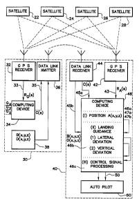
Illustrated in Figure 2 is a landing system in accordance with the present
35 invention. Thereshown are a plurality of satellites 22, 24, 26 and 28 which
each
transmit signals containing data for determining satellite range data between
a remote
receiver and each one of the plurality of satellites. Ground station 30
includes a GPS
receiver 32, a computing device 34 and data link transmitter 36. GPS receiver
32
WO 94/10582 ~ ~ PCT/US93/10582
may be any of a variety of GPS receivers well known in the art for selectively
receiving a plurality of satellite signals for subsequent determination of a
calculated
global position of the ground station as a function of the satellite range
data, i.e" the
pseudo range and pseudo range rate data derived from signals from selected
ones of
s the satellites in a well known manner. GPS receiver 32 includes an output 33
presented to computing device 34 for providing data representative of the
satellite
range data derived from the satellite signals as measured from the ground
station, and
is designated in Figure 2 as "RG(s)". In turn, computing device 34 receives
the
satellite range data for determining, if so desired, the coordinates of the
ground
station, identified as G (x, y, z) which represents particular coordinates Gx,
Gy and
Gz.
Computing device 34 further receives input data representative of the actual
coordinates of the ground station, namely G'x, G'y and G'z. At a particular
instant,
computing device 34 processes the satellite range data on signal line 33 with
the
I s known ground station coordinates for deriving satellite correction data
designated
"C(s)", and provides a data output indicative thereof on signal line 35. Here
C(s) is
the usual satellite correction data associated with differential GPS systems
known in
the art, and generally represents those satellite positioning systems errors
contained in
the satellite range data. Such errors include, among others, errors caused by
the
2o satellite clocks, the satellite's position, and ionospheric and atmospheric
delays. As is
well understood in the art, a second satellite signal receiver in the vicinity
of the
ground station may correct it's range and range rate data utilizing the
satellite
correction data in order to calculate a more accurate calculated global
position of the
second satellite signal receiver.
2s The data link transmitter 36 serves to transmit the correction data to any
mobile unit which includes a receiver means for establishing the data link
between the
ground station and the mobile unit. The data link transmitter may be any of a
variety
of radio transmitters, or the like, for establishing the data link between the
ground
station and the mobile unit.
3o In the present invention, the mobile unit is an aircraft indicated in
Figure 2 by
the dashed block 40 which includes a GPS receiver 42 and a data link receiver
44.
GPS receiver 42, similar to receiver 32, provides an output on signal line 43
representative of the satellite range data derived from the satellite signals
as measured
from the aircraft position, and is designated in Figure 2 as "RA(s)",
3s Data link receiver 44 receives as data from data link transmitter 36, the
transmitted data including the correction data C(s) and other such data
associated with
differential GPS systems. Data link receiver 44 presents this on the aircraft
on signal
line 45b, which in turn is presented as an input to computing device 46.
Computing
WO 94/10582 ~ ~ PCT/US93/1~2
device 46 includes computing section 46a which is intended to compute a
corrected
global position of the air craft A (x, y, z) as a function of the satellite
range data
RA(s) and the correction data C(s) in accordance with well known procedures
for
differential GPS positioning systems. As figuratively illustrated in Figure 2,
computing device 46 generates an output representative of the corrected global
position of the aircraft designated A (x, y, z), and the computing device 46
makes use
of such information as indicated by the arrow 47a.
It should be recognized by those skilled in the art that GPS receiver 42 and
GPS receiver 32 are substantially the same and may be commonly purchased from
the
1 o TRIMBLE firm and many other firms as known to those skilled in the art.
Further,
the description of the block diagram illustrated in Figure 2 refers to
separate
computing sections, signal lines, and specific blocks, etc. However, as is
known to
those skilled in the art, there are a variety of known analog and digital
implementations, including microprocessor based systems, for transferring and
15 processing data in accordance with the present invention.
It also should be recognized by those skilled in the art that the preceding
exposition has generally described a differential GPS system wherein the
ground
station transmits correction data C(s) in the form of satellite range and
range rate data
errors, and the aircraft corrects the GPS receiver range and range rate data
before the
2o aircraft position is first calculated. However, it should be understood
that other
differential GPS schemes beyond that shown herein are within the scope of the
present
invention. Therefore, the differential GPS system of Figure 2 has only been
illustrated in a manner to facilitate an understanding of the present
invention, and
therefore is only exemplary in nature.
25 In accordance with the present invention, ground station 30 is intended to
be
located in the vicinity of the landing strip in order to enhance the
differential GPS
solution for the aircraft's position A (x, y, z). Also, herein the correction
data has
been derived by the computing device 34 at the ground station and subsequently
transmitted by the data link transmitter 36. As is well understood in the art,
the
3o actual correction data could be computed in computing device 46 by data
transmission
of the calculated global position of the ground station and the known position
of the
ground station G' (x, y, z), as well as other identifying data so as to
optimize the
corrected global position of the aircraft, specifically that designated by A
(x, y, z).
All such schemes are intended to be within the spirit and scope of the present
35 invention.
As indicated earlier, associated with the landing strip is a selected desired
glide path for aircraft approaches, as already depicted in Figure 1. This
includes the
orientation of the ground track (i.e., line segment B'D) relative to World
Geodetic
WO 94/10582 ~ ~ ~ PCT/IJS93/10582
-'-
System, the glide slope angle (the angle between line segments B' D and glide
path
Line segment BD), and, of course, the glide path itself including the runway
threshold
crossing point D and point B, where points B and D define the desired glide
path.
All of this information may be supplied to the aircraft through the data link
s transmitter 36 by transmitting only the desired flight path coordinates B
(x, y, z) and
the runway threshold crossing point D (x, y, z). In the preferred embodiment,
the
runway threshold crossing point is generally a point in space having an
altitude of
approximately 50 feet from the Earth's surface and the glide slope angle is
typically
3 ° . However, in the present invention, any of these parameters may be
changed at
1 o any time by simply designating the geodesic coordinates B (x, y, z) and
the runway
threshold crossing point D (x, y, z).
Again referring now to Figure 2, data link receiver 44 includes data output
means 45b for presenting data inputs B (x, y, z) and D (x, y, z) to computing
device
46.
15 Computing device 46 serves multifunctions by appropriately executing a set
of
instructions in a manner well known in the art. For illustrative purposes,
computing
device 46 includes "sections" for executing certain tasks, and generally
refers to
portions of a computer program. Computing device 46 includes means for
processing
the correction data, C(s), the actual global position of the points B and D,
and the
2o calculated global position of the aircraft for (i) deriving a corrected
global position of
the aircraft A (x, y, z) as a function of the correction data, namely C(s) and
the
satellite range data RA(s), and (ii) derives the lateral deviation, "LD", and
the vertical
deviation, "VD", between the corrected global position of the aircraft and the
selected
glide path (BD) as a function of the actual global position of points B and D,
and the
2s corrected global position of the aircraft A (x, y, z) in a manner as will
now be
described.
First, the global position correction section 46a of computing device 46
calculates the corrected global position of the aircraft A (x, y, z). The
determination
of the corrected global position A (x, y, z) is done in a manner well known in
the art
3o in differential GPS, and will not be described herein.
The landing guidance section 46b for calculating the lateral and vertical
deviation will now be mathematically described with reference to Figure 1. It
should
be assumed in the following exposition that computer means 46 includes the
necessary
software and hardware in order to instrument the mathematical expressions
which
3s follow.
The first step executed by computing device 46 is the quantification of the
unit
normal vector N, passing through the center of the earth "O", and normal to
the
landing strip surface, plane M, at the selected altitude of the runway
threshold
WO 94/10582 ~, ~ ~ ~ PGT/US93/~2
_g_
crossing point D. The unit vector N is a vector which is collinear with a
vector OD
where O is the center of the Earth having coordinates (0, 0, 0) and the runway
crossing point D having coordinates (Dx, Dy, Dz). Accordingly, the unit normal
vector is: '
s
(D-O)
(1) N - Nxx + Nyy + Nzz -
~D-~)
(Dx-0)x + (Dy-0)y + (Dz-0)z
[ ~x-0)2 + (Dy-0)2 + (Dz-0)2 ] 1~
The altitude difference between the selected altitude of the runway crossing
point D (i.e., plane M) and the aircraft's present position A(x, y, z) is
illustrated as
the length of line segment dl. Distance dl is the length of line segment A'-A
which
is a line normal to the plane M. The position of the aircraft relative to the
runway
threshold crossing point D is identified as vector V 1. From vector algebra:
(2) V 1 = A-D
_ (Ax-Dx)x + (Ay-Dy)y + (Az-Dz)z
It follows that the distance dl is:
(3) dl - ~ Vl dot N ~
- ~ (VlxNx + VlyNy + VlzNz) ~
In order to calculate the lateral deviation, "LD", of the aircraft relative to
the
ground track B'-D, vectors describing the projection normal to plane M of the
glide
3o path vector V2, namely vector V4, and the aircraft position vector Vl,
namely vector
V3, are first determined. Vector V3 is a vector from point D to point A' ,
which is
the same as the projection of vector V1 into plane M. Accordingly:
(4) V3 - V 1-A' A
- Vl-d1N
- [ Vlx-(dlNx) ] x + [ Vly-(dlNy) ] y + [ Vlz-(dlNz) ] z
Next, the ground track vector V4 is determined. This is accomplished by first
calculating the distance d2 which is the distance between points B and B' ,
where B' is
4o in the plane M. Distance d2 is the altitude of the glide path
identification point B
above the runway threshold crossing point D. From vector analysis, it follows:
WO 94/10582 ~ ~ ~ PGT/US93/10582
(5) d2 - ~ V2 dot N ~
- ~ (V2xNx + V2yNy + V2ZNZ) ~
s where vector V2 is the glide path vector from point D, having coordinates
Dx, Dy,
DZ, to point B, having coordinates Bx, By, BZ, and N is the unit vector
defined
above. That is: (V2 = B - D)
It should be noted here that vector V2 is a selected glide path for a
particular
landing strip or runway, and is, of course, known. Further, vector V2 is
defined by
1o the known selected point coordinates "B" and "D" chosen for the particular
runway.
Next, the ground track vector V4, is a vector from point D to point B' where
point B' has coordinates (B'x, B'y, B'Z). Since V4 is the projection of vector
V2 into
plane M, from vector analysis it follows:
1 s (6) V4 - V2-d2N
- (V2x-d2Nx)x + (V2y-d2Ny)y + (V2Z-d2NZ)z
The lateral deviation, "LD", may now be determined as a function of the cross
product of vectors V3 onto vector V4 as follows:
(7) lateral deviation - LD - ~3xV4) dot N
~V4~
2s where N is defined in equation (1) and where:
(8) V3xV4 - (V3yV4Z-V4yV3Z)x + (V3xV4Z-V4xV3~y +
(V3xV4y-V4xV3y)z
3o and
(9) ~ V4 ~ - (V4x2 + V4y2 + V4Z2)'/~
The sign of the lateral deviation comes directly from the sign of the result
of
3s equation (7). That is, if the sign is positive, the lateral deviation is in
the same
direction as illustrated in Figure 1, and an opposite sign indicates that the
lateral
deviation is a lateral deviation relative to the desired glide path opposite
than that as
illustrated.
WO 94/10582 ~ ~ PGT/US93/1~2
t'~~4~~~.~
The distance of the aircraft from the runway threshold crossing point D along
the desired ground track is indicated by the distance d3, the length of the
line segment
between points D and C' . Distance d3 may be determined as follows:
s ~ V3 dot V4 ~
(10) d3 -
~V4~
(V3xV4x + V3yV4y + V3zV4z)
-
~V4~
Distance d4, the distance between points C' and C, defines the desired
altitude
of the aircraft along the desired glide path BD. The distance d4 may be
determined
~5 by a simple ratio of similar triangles as follows:
d2 ~ d4
(11) -
~ V4 ~ d3
from ( 11 ) it follows
(d2) (d3)
(12) d4 -
2s ~ V4 ~
Accordingly, the vertical deviation as previously defined may now be
determined. That is, the vertical deviation, "VD", is the difference between
the
distance dl, which is a function of the present position of the aircraft, and
the
3o distance d4 which is the desired position of the aircraft on glide path BD,
thus:
(13) Vertical Deviation = dl-d4
In the previous discussion, it has been shown that two points B and D define a
3s glide path relative to the runway threshold crossing point D. In turn,
knowledge of
the actual global position coordinates of these two points, namely D(x, y, z)
and B(x,
y, z), and knowledge of the position of the aircraft defined by the
coordinates A(x, y,
z) is the only information required by the onboard computer 46 for calculating
the
lateral deviation, "LD", and vertical deviation, "VD", relative to the
selected glide
4o path defined by points B and D.
In turn, data representative of LD and VD may be subsequently processed by
control signal processing section 46c of computer device 40 for generating
autopilot
data 50 for autopilot 60 as will now be further described.
WO 94/10582 ~ ~ PCT/US93/10582
As is well understood in the prior art, existing ILS systems provide steering
signals to the autopilot in signal quantity units called Difference in Depth
of
Modulation (DDMs). More specifically, on-board ILS systems components provide
steering signals referred to as lateral deviation DDM and vertical deviation
DDM. As
is well known, these steering signals are derived from the electromagnetic
signal
intensities of different frequencies radiated by transmitters in the vicinity
of the
landing strip. The vertical and the lateral deviation DDMs are essentially
proportional to the actual lateral deviation and the vertical deviation as
described with
reference to Figure 1. Accordingly, the lateral deviation and the vertical
deviation
derived above may be scaled to provide the "look and feel" of a DDM so that
such
signals can be fed directly into an autopilot in place of standard and
customary ILS
signals commonly employed in such systems, as well as in MLS systems.
However, in the present invention, the scaled DDM signals can be further
characterized by gain control signals as a function of the ground track
distance
relative to the runway threshold crossing point D, namely distance d3 defined
between points C' and D, or alternatively the magnitude of vector V3. In this
situation, computer 46 can provide information which simulates an ILS beam
lateral
and vertical difference in depth of modulation DDM as follows:
2o LD
(14) DDM (Lateral) - *G(d)
F(d)
where:
LD is the lateral deviation ,expressed in equation (7),
F(d) = Lateral deviation scale factor which is a function of the distance
of the aircraft from the runway threshold crossing point, and
G(d) = DDM scale factor which is a function of the distance of the
aircraft from the runway threshold crossing point. In a real
application of the GPS system this factor may simplify to a
constant.
Vert Dev
DDM (Vertical) - *K(d)
J(d)
4o where:
WO 94/10582 ~ ~ PCT/US93/1~2
. . ~ ; =-. .--~xi21444~2 _i2-
VD is the vertical deviation expressed in equation (14),
J(d) - Vertical Deviation Scale factor which is a function of the
distance of the aircraft from the runway threshold
crossing point.
and
1 o K(d) - DDM scale factor which is a function of the distance of
the aircraft from the runway threshold crossing point.
Of course, the distance selected may be other than that determined relative to
the runway threshold crossing point, e.g., a point on the ground at the end of
the.
~5 runway, and is within the spirit and scope of the present invention.
Control signal processing section 46c may perform the computation as just
described, or other control schemes as desired to properly direct autopilot
60.
In accordance with the present invention, the onboard station, which includes
the GPS receiver, the data link receiver and computing device, may determine
the
2o glide path and control signals for subsequent flight control without the
use of an
extensive data base and with no flight management system involvement. In the
present invention a flight management system may still be used to fly the
curved
approach to the final straight-in segment, i.e., the glide path, or an
additional point or
points from the fixed ground station could be used to construct a curve. In
this
25 embodiment, the aircraft implementation may be designed in such a way that
when
the ILS or MLS function was engaged in the final approach segment the
autopilot
would use a localizer and glide slope deviations, i.e., lateral deviation and
vertical
deviation, supplied by the onboard independent computer 46 through the ILS/MLS
input to the autopilot. The final flight segment can then be started at an
altitude high
3o enough to assure that the flight management system will be disengaged
before the
aircraft has descended below presently allowable altitudes as is done in
today's
architecture.
The advantages, among others, in accordance with the present invention allow
for a "drop in" replacement for ILS or MLS systems. It allows for a glide path
35 change in the glide slope as transmitted by the ground station by
transmission of the
global position of points 13 (x, y, z) and D (x, y, z).
In contrast with present day autopilots which respond to DDMs derived from
electromagnetic wave signals, autopilots may be redesigned to permit use of
only the
~WO 94/10582 ~ . : _ ~ ' ~ . PCT/US93/10582
13
"calculated" lateral deviation (LD), vertical deviation (VD), and distance
(d3) from
the runway threshold crossing point derived in manner in accordance with the
present
invention, as opposed to the less accurate or reliable differences in depth
modulation
signals modified by appropriate controlled gain functions in the usual ILS and
MLS
systems.
As is apparent to those skilled in the art, when the ground station transmits
the
actual global position coordinates of the runway threshold crossing point D,
and a
second point B, where B and D define the glide path, there is no need for any
database requiring knowledge of specific glide paths corresponding to specific
airport
io runways. This, of course, reduces the need for additional hardware on the
aircraft
and reduces the criticality of existing hardware. Therefore, only the hardware
of the
present invention needs to be FAA certified, whereas the existing aircraft
navigation
hardware, e.g. inertial nav and autopilot hardware, does not need to be re-
certified.
More specifically, since the system does not require any modification to the
autopilot
15 or the flight management system in its present form, there is not a need
for
recertification of any other hardware other than the GPS receiver and data
link
receiver in accordance with the present invention.
It should be recognized by those skilled in the art that a single fixed ground
station may provide data of a plurality of runways so that approaching
aircraft may
2o select the appropriate glide path for a specific runway by a simple channel
selection of
the data link transmitter/receiver system.
Figure 3 shows one example of a message which may be transmitted by the
data link transmitter 36. The message may include health/integrity data 310,
ephemeris data 320, runway coordinates/runway identification data 330 followed
by
25 satellite correction data 340, i.e., pseudo range corrections, i.e., C(s).
The
health/integrity message provides the required information used to confirm the
validity of the satellite signals used by both the ground station and aircraft
position
determinations in a manner which is customary. Ephemeris data provides
satellite
orbital information to the aircraft to ensure that the ground station and
aircraft are
30 operating from the same set of ephemeris data. The pseudo range corrections
provide
differential correction information used for increasing GPS accuracy in
accordance
with known art. The runway coordinates/identification provides the aircraft
with
runway coordinates, e.g., B(x, y, z) and D(x, y, z), from which to calculate
the final
approach and flight path as described with reference to Figure 1. Further, the
runway
35 coordinates/identification information may contain other enhancement
information
such as the runway identifier, runway threshold crossing height in terms of
its actual
global position, and runway threshold crossing altitude as desired.
WO 94/10582 2 ~ 4 4 ~ ~ ~ ~ PCT/US93/82
-14-
Figure 4 is another block diagram similar to Figure 2. In the following
Figures, similar functioning component shown in the Figures as those in Figure
2
have retained the same numeral designation. In Figure 4, thereshown is the
scenario
wherefore an aircraft is not equipped with a flight management system or
autopilot. '
In this situation, the pilot may input the ILS receiver frequency in a manual
control
430 as an input to the data link receiver 44 for appropriately obtaining the
desired
coordinates for the glide path associated with the runway having the inputted
ILS
frequency. As before, the computer device 46 calculates the lateral and
vertical
deviation from the desired glide path (B-D) and provides them as input to a
landing
l0 display altitude director indicator 440 for manual flight aircraft
approaches.
Also shown in Figure 4 is an alternate arrangement including an aircraft
equipped with an autopilot 60 but is not equipped with a flight management
system.
This system operates in a similar manner except that the determined lateral
and
vertical deviations from the glide path are made for control of the autopilot
in addition
I s to signals to the flight director.
Shown in Figure 5, similar to Figure 4, is a system in accordance with the
present invention in which the aircraft includes a flight management system
610,
including input controller 640, with autopilot 60. This system functions
similar to
that in Figure 4 except that the corrected global position of the aircraft A
(x, y, z) is
2o fed into the flight management system 610, and the flight management system
610 can
electronically control or provide the runway selection identifier into the
data link
receiver for proper runway coordinate point information selection.
Illustrated in Figure 6 is another embodiment of the present invention in
which
the similar function components as those shown in Figure 2 have retained the
same
25 numeral designations. In Figure 6, the data link transmitter further
includes inputs
from approach curvature data block 700. Block 700 provides actual global
position
data, P(n), for constructing a flight path approach curvature intended to be
flown by
an aircraft before descending down the glide path. In turn, data link receiver
44
provides data on signal line 45c to computing device 46 having a curvature
deviation
3o section 46c. Since in the present invention the corrected global position
of the
aircraft is known, the curvature deviation section may then compute the
deviations
between the current aircraft position and the known approach curvature points
P(n).
In turn, curvature deviation signal processing section 48c of computer device
46 may
subsequently provide signal inputs to an autopilot 60 or other navigating or
indicating
35 equipment 70.
It should be understood that there are many types of receivers for
differential
as well as non-differential positioning by satellite which can be incorporated
in the
system of the present invention. Further, there are many types of data link
WO 94/10582 ~ , PGT/US93/10582
transmitters and receivers which may be incorporated in the present invention
and
may have a plurality of channels and/or frequencies which may be utilized,
including
those incorporated in ILS and MLS systems.
Furthermore, it should be recognized that only one ground station has been
s associated with one landing strip or runway, however, it is within the scope
of the
present invention that the data link transmitter may transmit a variety of
distinct data
packets corresponding to a plurality of landing strips on either the same
frequency
channel or a plurality of different channels, and is also intended to be
within the scope
of the present invention.
1 o It should be noted that the vector analysis presented is an exact method
for an
earth centered sphere. However, it is within the scope of the present
invention to
incorporate other mathematical expressions beyond that shown herein to arrive
at the
same intended function as disclosed herein, i.e., lateral and vertical
deviation from
the desired glide path. For example, corrections may be required for an
"elliptical"
15 earth, or other fixed coordinate system for global positioning reference
system.
Lastly, although it has been shown that only two points need be communicated
from the ground station to the aircraft to define the glide path, one being
the runway
threshold crossing point, other information may also be transmitted and is
intended to
be within the spirit and scope of the present invention, such as provided by
various
2o enhancements not shown herein, but useful to those artisans in flight
management.
. ~s~~u :.