Language selection

Search

Patent 2144444 Summary

Third-party information liability

Some of the information on this Web page has been provided by external sources. The Government of Canada is not responsible for the accuracy, reliability or currency of the information supplied by external sources. Users wishing to rely upon this information should consult directly with the source of the information. Content provided by external sources is not subject to official languages, privacy and accessibility requirements.

Claims and Abstract availability

Any discrepancies in the text and image of the Claims and Abstract are due to differing posting times. Text of the Claims and Abstract are posted:

  • At the time the application is open to public inspection;
  • At the time of issue of the patent (grant).
(12) Patent: (11) CA 2144444
(54) English Title: VENTED PLASTIC BOTTLE
(54) French Title: BOUTEILLE DE PLASTIQUE AVEC PRISE D'AIR
Status: Expired
Bibliographic Data
(51) International Patent Classification (IPC):
  • B65D 25/38 (2006.01)
  • B65D 1/02 (2006.01)
  • B65D 1/20 (2006.01)
  • B65D 25/28 (2006.01)
  • B65D 25/40 (2006.01)
(72) Inventors :
  • RING, CARL D. (United States of America)
(73) Owners :
  • RING CAN CORPORATION (United States of America)
(71) Applicants :
(74) Agent: NORTON ROSE FULBRIGHT CANADA LLP/S.E.N.C.R.L., S.R.L.
(74) Associate agent:
(45) Issued: 1998-02-10
(86) PCT Filing Date: 1994-04-11
(87) Open to Public Inspection: 1995-01-26
Examination requested: 1995-11-30
Availability of licence: N/A
(25) Language of filing: English

Patent Cooperation Treaty (PCT): Yes
(86) PCT Filing Number: PCT/US1994/003909
(87) International Publication Number: WO1995/002352
(85) National Entry: 1995-03-10

(30) Application Priority Data:
Application No. Country/Territory Date
08/090,760 United States of America 1993-07-13

Abstracts

English Abstract


A container having a neck arrangement
including a circular spout (30) and a guiding neck
portion with a U-shaped ledge (60). During a pouring
operation the ledge directs liquid from the
container over the front edge of the spout (78) and
permits air to enter the container through the rear
portion of the spout (63) and an air passageway
(58) connecting the rear of the spout with the
inside of the container.


French Abstract

Contenant dont le goulot est constitué d'un dispositif muni d'un bec circulaire (30) et d'un support de guidage en forme de U (60). Lorsqu'on déverse un liquide, le rebord de ce support fait passer ce liquide par-dessus le bord antérieur du bec (78) tout en laissant entrer l'air dans le contenant par une section située à l'arrière du bec (63) et par un passage (58) pratiqué entre la section arrière du bec et l'intérieur du contenant.

Claims

Note: Claims are shown in the official language in which they were submitted.


CLAIMS

1. A plastic container (10) comprising a bottom wall (12), front
(14), rear (16), and side walls (18, 20) extending vertically from said
bottom wall (12) defining a chamber (22) having a generally rectangular
cross-section, a top wall (24) covering a substantial portion of said
chamber, a neck platform (30) extending upwardly from said top wall
adjacent said front wall and having a circular pouring spout (40) with an
open end, means (50) connected to said platform defining an air
passageway (58) from said spout to said chamber, said platform including
a guiding neck portion (54) connected to said top wall below said spout
and having a generally U-shaped horizontal ledge (60) as viewed from the
open end of said spout and opening toward said front wall, said U-shaped
ledge having a rear edge (62) which is generally parallel to said front wall
and side edges (66, 68) extending from said rear edge (62) toward said
front wall, said rear edge and said side edges being spaced inwardly from
the rear edge (63) and side edges (65, 64), respectively, of said spout,
whereby during a pouring operation said U-shaped ledge directs liquid
from said chamber over the front edge (78) of said spout away from the
rear edge of said spout thereby permitting air to enter the rear of said
spout into said air passageway and said chamber.


2. The plastic container of claim 1, said U-shaped ledge (60) being
generally parallel to said top wall (24).


3. The plastic container of claim 1, wherein said means defining
said air passageway (58) is a hollow handle (50) extending from said
platform (30) to said rear wall (16).

4. A plastic container (10) comprising a bottom wall (12), front
(14), rear (16), and side walls (18, 20) extending vertically from said
bottom wall defining a chamber (22) having a generally rectangular cross-section,
a top wall (24) covering a substantial portion of said chamber, a
neck platform (30) extending upwardly from said top wall and having a
circular pouring spout (40) having a central axis and an open end, means
(50) connected to said platform defining an air passageway (58) from said
spout to said chamber, said platform including a guiding neck portion (54)
connected to said top wall below said spout and having a generally
U-shaped horizontal ledge (60) as viewed through the open end of said spout
and opening toward a front edge (78) of said spout, said U-shaped ledge
having a rear edge (63) which is generally transverse of said spout axis and
side edges (66, 68) extending from said rear edge (63) toward the front
edge (78) of said spout, said rear edge and said side edges of said ledge


being spaced inwardly from the rear edge (63) and side edges (65, 64),
respectively, of said spout, whereby during a pouring operation said
U-shaped ledge directs liquid from said chamber over the front edge (78) of
said spout away from the rear edge (63) of said spout thereby permitting
air to enter the rear of said spout into said air passageway (58) and said
chamber.

5. The plastic container of claim 4, said U-shaped ledge (60) being
generally parallel to said top wall.


6. The plastic container of claim 4, wherein said means defining
said air passageway is a hollow handle (50) extending from said platform
to said chamber.

7. A plastic container comprising a bottom wall (12), side wall
means (14, 16, 18, 20) extending vertically from said bottom wall defining
a chamber (22), a top wall (24) covering a substantial portion of said
chamber, a neck platform (30) extending upwardly from said top wall and
having a circular pouring spout (40) having a central axis and an open end,
means (50) connected to said platform defining an air passageway (58)
from said spout (40) to said chamber (22), said platform including a


11

guiding neck portion (54) connected to said top wall below said spout and
having a generally U-shaped horizontal ledge (60) as viewed through the
open end of said spout and opening toward a front edge (78) of said
spout, said U-shaped ledge having a rear edge (62) which is generally
transverse of said spout axis and side edges (66, 68) extending from said
rear edge (62) toward the front edge (78) of said spout, said rear edge
(62) and said side edges (66, 68) of said ledge being spaced inwardly from
the rear edge (63) and side edges (65, 64), respectively, of said spout,
whereby during a pouring operation said U-shaped ledge directs liquids
from said chamber over the front edge (78) of said spout away from the
rear edge (63) of said spout thereby permitting air to enter the rear of said
spout into said air passageway (58) and said chamber.


8. The plastic container of claim 7, wherein said means defining
said air passageway is a hollow handle (50) extending from said platform
to said chamber.


Description

Note: Descriptions are shown in the official language in which they were submitted.


WO 9S/023~;2 1 PCT/US94/03909

2i44~


VENTED PLASTIC BOl~LE


TECHNICAL FIELD
This invention relates generally to containers for dispensing liquid
and more specifically to a container having a novel pouring spout
arrangement by which the space above the liquid is vented to permit air
to be drawn into the space during a pouring operation to prevent the
glugging or gulping phenomenon associated with many conventional
bottles.
This invention is particularly applicable to blow-molded plastic jugs
or bottles used for dispensing a variety of different types of liquids, some
of which may be toxic or fl~mm~ble. As the bottle is tipped forwardly, the
mouth or neck portion will normally be lowered below the liquid level in
the bottle, trapping the air in the bottle above the liquid. If no vent is
provided to admit air into this region, the flow of liquid out of the bottle
will alternate with the flow of air into the jug, causing a glugging or gulping
action. Because of the glugging action the poured stream is difficult to
control, so that the user may make a mess with the liquid. When that
liquid is toxic or fl~mm~ble this can create a dangerous situation.


WO 95/02352 PCT/US94/03909


BACKGROUND ART
In the past, various attempts have been made to provide containers
with a vent feature to overcome this glugging problem. Typical prior
proposals are illustrated in U.S. Patents 3,251,514, 4,412,633, 4,804,119,
and in PCI International Publication No. W0-86/02334, and those designs
are improvements over the conventional bottles.
In larger blow molded plastic bottles, for example 35 pound or 2
gallon jugs, it is desirable that the neck area be both level and strong
because the automatic filling and capping machines which are used to fill
the jugs require a dimensionally consistent and strong neck to work
efficiently. U.S. Patent 5,144,028, assigned to the assignee of this
application prece~les a bridge top construction to maintain the level
position. Applicant has discovered that it is very desirable to provide a
bottle of the type illustrated in Patent 5,144,028 with a spout arrangement
which alleviates the glugging action during a pouring operation.


DISCLOSURE OF THE INVENTION
A primary object of the invention is to provide a container with a
novel neck construction which eliminates glugging action as liquid is
poured from the container.


wo ss/023s2 2I ~ PCT/US94/03909


Still another object of this invention resides in the provision of a
cont~iner having novel neck arrangement, including a neck and handle
design which form a bridge between the front and rear walls of the
cont~iner and a guiding neck portion which deflects the liquid toward the
forward edge of the outlet spout of the bottle as the liquid is poured from
the bottle.
Still another object of the invention resides in the provision of a
container as described above wherein the outlet spout is displaced axially
rearwardly of the axis of the guiding neck portion, and the rearward
position of the spout communicates with a hollow handle to permit air to
freely enter into the bottle during a pouring operation.
These and other objects of the invention will become apparent from
re~-linE the following detailed description of the invention in which
reference is made to the accompanying drawings wherein like numerals
indicate like elements.


BRIEF DESCRIPTION OF DRAVVINGS
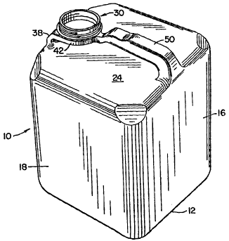
Figure 1 is a generally perspective view of the novel blown plastic
bottle of the invention.

Figure 2 is a top plan view of the bottle.

WO 95102352 PCT/US94/03909
. --
2i~


Figure 3 is a side elevational view of the bottle taken along line 3-3
of Figure 2.
Figure 4 is a fragmentary sectional view taken along line 4-4 of
Figure 2.
Figure 5 is a fragmentary sectional view taken generally along line
5-5 of Fig. 4; and
Figure 6 is a similar view to Figure 4, but illustrating the bottle in
its tilted position in which liquid is poured from the bottle.


~EST MODE FOR CARRYING OUT THE INVENTION
Referring now to the drawings, the one piece blow molded plastic
container or bottle 10 includes bottom wall 12, vertical front wall 14, rear
wall 16, and side walls 18 and 20 which define a liquid cont~ining chamber
22 of generally rectangular cross section and a top wall 24 joining walls 14,
16,18, and 20 to close chamber 22.
Integrally formed on top of wall 24 adjacent front wall 14 is a neck
platform 30 having a forward wall 32 including a vertical section 34 which
extends along and coextensively upwardly from wall 14 and blends with a
rearwardly tapered section 36 which terminates in a top wall portion 38 on
which is formed a circular threaded outlet spout 40 normally closed by a


WO 95/02352 PCT/US94/03909


cap (not shown). Platform 30 includes a pair of side walls 42 and 44 which
extend rearwardly from front wall 14 generally parallel to side walls 20 and
22 to a point about the diametral line of spout 40 and then around the
spout to a junction area 46 where they join with a narrow hollow handle
50 which is connected at its rearward end 52 to wall 16.
Platform 30 also includes a guiding neck portion 54 connected
between and blending with top wall 24 and side walls 42 and 44. Side
walls 42 and 44 define a transitional chamber 56 which extends from
tapered front wall 36 to area 46 where it connects to the forward end of
an air passageway 58 defined by hollow handle 50, the rearward end of
p~s~eway 58 extending through top wall 24 and communicating with
chamber 22.
As seen best in Figures 2, 4, and 5, guiding portion 54 forms a
horizontal generally U-shaped ledge 60 having a rear portion 62 extending
fol ~ardly of juncture 46 and the rear edge 63 on a diametral line of spout
40 which is parallel to side walls 20 and 22. Ledge 60 also includes side
sections 66 and 68 which blend with rear section 62. The inner edge of
section 62 runs generally parallel to front wall 14 and the inner edges of
side sections 66 and 68 run generally parallel to walls 20 and 22. Together
~ose inner edges form a generally U-shaped pouring edge 70 which


WO 95/02352 PCTrUS94/03909


diverges outwardly at 72 and 74 to intersect with side walls 42 and 44
adjacent the front wall 36. As shown in Figure 2, those inner edges are
sp~ce-l in~aldly from the rear edge 63 and from the side edges 64 and 65
in a diametral line of spout 40 which is parallel to front wall 14 so as to
deflect and guide the liquid from chamber 22 into the front portion of
chamber 56 and over the front edge 78 of spout 40 away from the rear
edge 63 and the side edges 64 and 65 on a diametral line of spout 40
which is parallel to front wall 14 so as to deflect and guide the liquid from
chamber 22 into the front portion of chamber 56 and over the front edge
78 of spout 40 away from the rear edge 63 and the side edges 64 and 65
of the spout as shown in Figure 6. This permits air indicated by arrow 80
to enter the spout along side edges 64 and 65 and rear edge 63 into
passageway 58 and into chamber 22 preventing the unwanted glugging
action.


The U-shaped edge 70 diverts the liquid stream away from the sides
and rear of the spout, producing a smaller area but higher velocity of
liquid flow over front edge 78 and elimin~ting spillover over the side edges
64 and 65.


WO 9~/02352 PCT/US94/03909
~ 2 1 ~


The edge 70, as it blends with the forward portions of walls 42 and
44 and tapered wall 36, forms a constrictive, directional neck area 82
which has a cross-sectional area greater than the cross-sectional area of the
outlet formed by spout 40. Also, as is evident in Figure 2, the axis of
spout 40 is displaced rearwardly toward the handle from the axis of the
opening defined by edge 70 and this ensures that the liquid is properly
deflected, as shown in Figure 6, to prevent any glugging action.
The construction of the platform 30 and handle S0 not only provides
the desired no-glugging function, but also retains the strength referred to
in Patent 5,114,028, nece~s~ry to maintain the spout 40 in a level position
and to resist downward deflection of the spout during the filling operation.
The invention may be embodied in other specific forms without
departing from the spirit or essential characteristics thereof. The present
embodiment is therefore to be considered in all respects as illustrative and
not restrictive, the scope of the invention being indicated by the appended
claims rather than by the foregoing description, and all changes which
come within the me~ning and range of equivalency of the claims are
therefore intended to be embraced therein.


Representative Drawing
A single figure which represents the drawing illustrating the invention.
Administrative Status

For a clearer understanding of the status of the application/patent presented on this page, the site Disclaimer , as well as the definitions for Patent , Administrative Status , Maintenance Fee  and Payment History  should be consulted.

Administrative Status

Title Date
Forecasted Issue Date 1998-02-10
(86) PCT Filing Date 1994-04-11
(87) PCT Publication Date 1995-01-26
(85) National Entry 1995-03-10
Examination Requested 1995-11-30
(45) Issued 1998-02-10
Expired 2014-04-11

Abandonment History

There is no abandonment history.

Payment History

Fee Type Anniversary Year Due Date Amount Paid Paid Date
Application Fee $0.00 1995-03-10
Registration of a document - section 124 $0.00 1996-03-07
Maintenance Fee - Application - New Act 2 1996-04-11 $100.00 1996-04-10
Maintenance Fee - Application - New Act 3 1997-04-11 $100.00 1997-04-10
Final Fee $300.00 1997-10-29
Maintenance Fee - Patent - New Act 4 1998-04-14 $100.00 1998-04-08
Maintenance Fee - Patent - New Act 5 1999-04-12 $150.00 1999-04-06
Maintenance Fee - Patent - New Act 6 2000-04-11 $150.00 2000-03-21
Maintenance Fee - Patent - New Act 7 2001-04-11 $150.00 2001-03-20
Maintenance Fee - Patent - New Act 8 2002-04-11 $150.00 2002-03-08
Maintenance Fee - Patent - New Act 9 2003-04-11 $150.00 2003-03-05
Maintenance Fee - Patent - New Act 10 2004-04-12 $250.00 2004-03-15
Maintenance Fee - Patent - New Act 11 2005-04-11 $250.00 2005-03-21
Maintenance Fee - Patent - New Act 12 2006-04-11 $250.00 2006-03-17
Back Payment of Fees $250.00 2006-03-29
Maintenance Fee - Patent - New Act 13 2007-04-11 $250.00 2007-03-08
Maintenance Fee - Patent - New Act 14 2008-04-11 $250.00 2008-03-07
Maintenance Fee - Patent - New Act 15 2009-04-13 $450.00 2009-03-16
Maintenance Fee - Patent - New Act 16 2010-04-12 $450.00 2010-03-19
Maintenance Fee - Patent - New Act 17 2011-04-11 $450.00 2011-03-09
Maintenance Fee - Patent - New Act 18 2012-04-11 $450.00 2012-03-14
Maintenance Fee - Patent - New Act 19 2013-04-11 $450.00 2013-03-14
Owners on Record

Note: Records showing the ownership history in alphabetical order.

Current Owners on Record
RING CAN CORPORATION
Past Owners on Record
RING, CARL D.
Past Owners that do not appear in the "Owners on Record" listing will appear in other documentation within the application.
Documents

To view selected files, please enter reCAPTCHA code :


To view images, click a link in the Document Description column. To download the documents, select one or more checkboxes in the first column and then click the "Download Selected in PDF format (Zip Archive)" or the "Download Selected as Single PDF" button.

List of published and non-published patent-specific documents on the CPD .

If you have any difficulty accessing content, you can call the Client Service Centre at 1-866-997-1936 or send them an e-mail at CIPO Client Service Centre.


Document
Description 
Date
(yyyy-mm-dd) 
Number of pages   Size of Image (KB) 
Cover Page 1995-08-31 1 14
Claims 1997-03-23 3 87
Description 1997-03-23 9 235
Abstract 1995-01-26 1 48
Description 1995-01-26 7 232
Claims 1995-01-26 4 136
Drawings 1995-01-26 4 106
Cover Page 1998-02-16 1 38
Representative Drawing 1998-01-23 1 16
Correspondence 2006-05-08 1 13
Correspondence 2007-08-28 1 18
Fees 2006-04-20 1 24
Correspondence 1997-10-29 1 48
PCT Correspondence 1995-11-30 1 51
Office Letter 1995-12-20 1 40
Examiner Requisition 1995-04-21 1 21
Prosecution Correspondence 1996-01-17 2 44
Prosecution Correspondence 1995-11-30 2 55
International Preliminary Examination Report 1995-03-10 1 51
Correspondence 2005-05-03 1 13
Correspondence 2006-04-04 1 14
Correspondence 2006-04-12 1 1
Fees 2006-03-24 1 35
Fees 2006-03-24 1 43
Correspondence 2007-05-15 1 20
Correspondence 2007-09-20 1 11
Correspondence 2007-08-03 5 215
Fees 1996-04-10 1 61
Fees 1997-04-10 1 62