Note: Descriptions are shown in the official language in which they were submitted.
2144~81
TSM 0126 PCA
METHOD AND SYSTEM FOR
HOT AIR SPRAY COATING AND
ATOMIZING DEVICE FOR USE l~KEIN
Technical Field
This invention relates to methods and systems
for air spray coating and atomizing devices for use
therein and, in particular, to methods and systems for
air spray coating and atomizing devices for use therein
wherein the air has a relatively high flow rate, a
relatively low delivery pressure (i.e. HVLP) and a
relatively high temperature at a spray head of the
atomizing device to atomize and help dry a coating
material.
B~.kground Art
Many state and federal agencies require that
all products produced with ozone-depleting substances
such as solvents be labeled as such. These same agen-
cies also will not allow new adhesive spray installa-
tions to be installed without very expensive solvent
burners to clean recirculate solvent-laden air.
One solution to this problem is to switch from
solvent-based adhesives to water-based adhesives which
contain little or no solvents. When a water-based
adhesive is applied by conventional or high volume, low
pressure (HVLP) guns, tremendous processing problems
results such as longer "tack time." This is also called
"green strength."
214~
-
TSM 0126 PCA -2-
With solvent-based adhesives, an operator
could process his/her parts very quickly due to quick
solvent evaporation. With water-based adhesives, there
is a significant waiting time between spray and process.
This is due to the water which must be evaporated. Most
water-based adhesives are 30~ to 50~ water by weight.
For example, an 8 lb. gallon of water-based adhesive
contains 2~ lbs. to 4 lbs. of water. A substantial
portion of the water must be evaporated before "tack" is
achieved.
Operations such as repairing foam cushions,
sticking pieces of foam together, applying fabric, etc.
can easily take 3 to 5 times longer with water-based
adhesive if no assist is given to the process. Many
plants have attempted to install special heating units
in order to dry the water-based adhesive and traps water
under the surface. Even with additional ovens, process-
ing time is increased dramatically. Many mechanical
means have been attempted. Hot air guns similar to hair
dryers have been used after spraying water-based adhe-
sive with a conventional gun. This doubles operator
application time.
All of these measures require more capital
investment by increasing the length of processing lines,
adding more ovens and establishing accumulating areas
for the parts. More operators are needed as well to
keep up with line speeds.
U.S. Patent No. 4,761,299 discloses a method
and apparatus for spray coating an article in a coating
zone with a liquid coating material, such as paint,
wherein air is supplied to the spray head of an air
2144581
TSM 0126 PCA -3-
spray gun at an atomizing air flow rate in excess of 5
CFM and at a delivery pressure of less than 15 psi to
atomize the liquid coating material. A turbine unit
filters and heats the air so that the air has a tempera-
ture in excess of 70-F at the spray head. However, this
temperature is not high enough to properly dry a water-
based adhesive.
Japanese Patent Document JA 9,042,032 disclos-
es, in its translation, a hot air atomizer for helping
to disperse suspended liquid such as a watery liquid.
The atomizer is a non-air atomizing rotary bell or disk.
Material is atomized by electrostatic centrifugal means
and air is used for shaping only. The hot air is used
to lower viscosity of thick materials which have a
tendency to block fluid dispensing openings. Air
temperature is 100 to 120-F.
U.S. Patent No. 4,667,084 discloses an adhe-
sive spray gun system that uses an electrically heated
hot air system for atomizing a melted adhesive. A
heater hose heats both hot melt adhesive and atomizing
air. A hot melt adhesive is 100~ solids in block form.
It is then melted into a thick liquid for application.
The purpose of the hot air is to keep the hot melt from
drying in the hose or on the gun.
U.S. Patent No. 5,102,484 discloses an adhe-
sive spray system using a hot gas, such as hot air, to
keep the adhesive soft prior to working. There is no
mention of atomizing hot melt viscous material. Hot gas
at the applicator head keeps viscosity down and assist
in swirling the patterns but the hot gas does not mix
with the material.
21~581
`
TSM 0126 PCA -4-
U.S. Patent No. 4,964,569 discloses a warm air
spray system for preventing the formation of condensa-
tion in its supply and return lines. Warm air under
high pressure is used in "any desired spray device."
The purpose is to reduce condensation in atomizing
lines.
U.S. Patent No. 4,669,661 discloses a hot melt
glue sprayer that uses heated air to ensure that the hot
melt sprays efficiently and accurately. A hot melt glue
gun uses high pressure hot air to keep glue soft and
applicable.
U.S. Patent No. 3,776,462 discloses a sprayer
for molten metal that uses heated air under pressure to
atomize the spray. Hot air heats metal to keep it
molten. High pressure air "propels atomized particles
at high velocity onto the surface to be coated."
U.S. Patent No. 4,785,996 discloses an adhe-
sive spray system that uses a plunger mechanism for
allowing adhesive to be released into a spray cavity.
High pressure cold air is used to divert "bead of
extruded hot melt adhesive."
U.S. Patent No. 3,796,376 discloses a spray
gun that has a trigger actuated plunger to control the
flow of liquid. High pressure cold air is emitted
through a special valve/plunger mechanism in the handle
of the gun.
U.S. Patent No. 5,076,469 discloses a spray
gun system that uses a heated gas to ensure a better
application of hot melt adhesives or the like. The gun
214~581
TSM 0126 PCA -5-
uses an electrical resistance heater to keep hot melt
adhesive molten. Compressed gas (air) is heated under
high pressure.
U.S. Patent No. 4,925,101 discloses a wax
spray gun that uses an operating plunger mounted with an
air valve to allow atomizing air to be admitted to the
wax. Cold atomizing air is used under high pressure.
S~lmm~ry Of The Invention
An object of the present invention is to
provide a method, system and hot air atomizer for use
therein which solves the problems of the prior art by
allowing quick dry or "tack times." The atomizer mixes
hot HVLP air with the coating material and drives or
evaporates a base of the coating material out quickly
before coating an article. When the coating material is
a water-based adhesive, processing times for the water-
based adhesive is similar to that for a solvent-based
adhesive.
In carrying out the above object and other
objects of the present invention, a method is provided
for hot air spray coating an article with a coating
material including a base. The method includes the
steps of supplying hot air to an atomizing device having
a spray head and supplying the coating material to the
atomizing device. The method also includes the step of
thermally insulating the hot air from the coating
material to prevent polymerization of the coating
material and utilizing the hot air entering the atomiz-
ing device to atomize the coating material to obtain
atomized coating material including the base at the
21~581
TSM 0126 PCA -6-
spray head. The hot air has a flow rate in excess of 5
CFM at the spray head, a delivery pressure of less than
15 psi over atmospheric pressure at the spray head, and
a temperature in excess of 200-F at the spray head to
evaporate a substantial portion of the base from that
atomized coating material before coating the article.
Preferably, the delivery pressure at the spray
head is in the range of 2-12 psi over atmospheric
pressure, the flow rate at the spray head is in excess
of 15 CFM, and the temperature of the hot air at the
spray head is in the range of 250-F to 350-F.
Also, preferably, the base may be water, a
solvent, or a mixture of water and solvent.
Further in carrying out the above object and
other objects of the present invention, a system is
provided for carrying out each of the above method
steps.
Still further in carrying out the above object
and other objects of the present invention, an atomizing
device for use in the above method and system is provid-
ed. The atomizing devices includes a body, a spray head
mounted on the body, an input coating passage for
receiving a coating material including a base, and a
separate input air passage for receiving hot air. The
atomizing device also includes means for thermally
insulating the hot air from the coating material to
prevent polymerization of the coating material within
the atomizing device. The hot air atomizes the coating
material at the spray head to obtain atomized coating
material including the base. The hot air has a flow
214~581
-
TSM 0126 PCA -7-
rate in excess of 5 CFM at the spray head, a delivery
pressure of less than 15 psi over atmospheric pressure
at the spray head, and a temperature in excess of 200F
at the spray head to evaporate a substantial portion of
base from the atomized coating material before coating
the article.
The advantages accruing to the method, system
and atomizing device described above are numerous. For
example, when the coating material is a water-based
adhesive, the adhesive is dried in about the same amount
of time that it takes for a solvent-based adhesive to
dry in a conventional spray coating system. Also, there
is no need to provide special heating units to dry the
water-based adhesive.
The advantages of the present invention will
be readily appreciated as the same can be better under-
stood by reference to the following detailed description
when taken in connection with the accompanying drawings.
Brief Description Of The D~a~vi..gs
FIGURE 1 is a side elevational view of an
atomizing device for use in the method and system of the
present invention;
FIGURE 2 is a rear elevational view of the
atomizing device of Figure 1;
FIGURE 3 is a sectional view of the atomizing
device taken along lines A-A of Figure 2;
219~581
TSM 0126 PCA -8-
FIGURE 4 is a schematic view, partially broken
away, illustrating the method and system of the present
invention; and
FIGURE 5 is a front elevational view of a
spray head of the atomizing device.
Best Mode For Ca~ Out The Invention
Referring now to the drawings figures, there
is illustrated in Figures 1 through 5 a hot air spray
gun method and system which utilizes high volume, low
pressure (HVLP) hot air to atomize and apply a coating
material such as a water-based adhesive to a substrate
in such a way so as to dry the water-based adhesive
quickly. The method and system may also be utilized
with a water-based paint which, like the water-based
adhesive, may include a small amount of solvent. Also,
the coating material may be a solvent-based, high
viscosity (i.e. high solid) paint such as a polyester or
urethane.
The method and system utilize an atomizer or
atomizing device such as the spray gun illustrated in
the drawing figures. The spray gun may be either of the
manual or automatic type. Both types are preferably
made of lightweight machinable plastic which makes the
atomizer both ergonomic and robot friendly. In other
words, the atomizer is lightweight.
The atomizer typically includes a gun body,
generally indicated at 5, which has an integrally formed
gun hook 6, for supporting the atomizer. The atomizer
also includes a spray head including air cap, generally
21 i~581
TSM 0126 PCA -9-
indicated at 7, which is also preferably made from
machinable plastic to provide thermal insulation and
prevent accidental burns. In general, the air cap 7 is
specially designed to use high volume, low pressure
(HVLP) hot air and direct the hot air toward the water-
based adhesive. Also, air temperature is preferably in
the range of 250 F to 350F at the air cap. The volume
of the hot air is preferably in the range of 25 to 35
CFM and the static pressure is preferably in the range
of 4 lbs. to 10 lbs. per square inch (psi).
Referring now to Figure 5, the air cap 7
includes a central hole 46a and circumferentially spaced
holes 46b which are sized and angled to correctly
atomize the adhesive and give desirable particle size.
Also, the air cap 7 prevents material build-up which can
distort the fan and cause interruption of material flow.
Preferably, the central atomizing hole 46a is in the
range of 4 millimeters to 8 millimeters in diameter.
Also, preferably, the fanning holes 46b are in the range
of 3 millimeters to 7 millimeters in diameter. The
fanning holes 46b can either be in opposing relationship
or assume a circle pattern around the atomizing hole 46a
as illustrated in Figure 5. Obviously, the various
configurations of the fanning holes 46b can supply a
round pattern of adhesive or a flat pattern depending on
application requirements.
The air cap 7 also preferably includes an air
cap shroud 11 which is threadedly secured to a gun
collector 12 of the spray head. The shroud 11 surrounds
the holes 46a and 46b and thermally insulates the spray
head of the atomizer by holding in hot air and prevents
the hot air from dissipating. The shroud 11 also helps
2144581
TSM 0126 PCA -10-
to concentrate the drying effect of the hot air. The
shroud 11 is particularly useful when the method, system
and atomizer device are utilized for foam repairs.
Preferably, if the air cap 7 has any metal
portions, they are Teflon-coated to allow the atomizing
device to be easily cleaned.
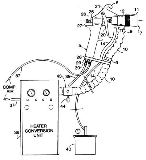
The atomizer device also includes barb fit-
tings 8a and 8b, one of which extends through gun
bracket 28. The barb fittings 8a and 8b cooperate with
spaced, hot air hose clamps 9 to secure a pair of hot
air hoses 10 to the atomizing device. One of the hot
air hoses 10 extends between the gun bracket 28 and the
gun collector 12.
As illustrated in Figure 3, each of the hoses
10 preferably comprises a special lightweight flexible
insulated hose having an internal diameter of approxi-
mately 3/4 inch to carry the high volume of heated air
from a heater conversion unit 38 to the atomizer device.
The hose 10 preferably comprises a relatively rigid
inner layer 10a to keep the hose 10 from collapsing and
an outer glass insulated sheath 10b which keeps the heat
from the heated air from escaping from the hose. Such
escaping heat might cause polymerization of the water-
based adhesive in a fluid hose 14. Preferably, the
insulated sheath 10b can withstand hot air up to 500-F.
An atomizing pressure air inlet or passage
defined by the inlet barb fitting 8b is also preferably
approximately 3/4 inch in diameter so that pressure into
the atomizing device is substantially the same as the
pressure at the exit of the air cap 7. One advantage of
21~581
TSM 0126 PCA -11-
this relatively low pressure is that the glue particles
in the water-based adhesive have a lower velocity and
stay on top of foam pieces when foam pieces are being
repaired, rather than being forced into recesses of the
foam where no contact-can be made.
The atomizer also includes a fluid barb
fitting 13 which also extends through the gun bracket
28. A collector barb fitting 15 is threadedly secured
to the atomizing device at one end thereof and at the
opposite end thereof receives thereover the fluid hose
14 which extends between the barb fittings 13 and 15.
The barb fitting 15 helps define an input coating
passage in the collector 12. The fluid hose 14 conveys
the water-based coating material or adhesive to the
collector 12.
As can be readily appreciated, the fluid hose
14 is thermally insulated from the hot air hose 10 so
that the hot atomizing air does not prematurely set the
liquid-based adhesive therein.
The atomizing device also includes a collector
nut 16 which secures a collector fluid tube, generally
indicated at 17 in Figure 3, within the gun body 5. The
collector nut 16 is threadedly secured at a threaded
portion 17a of the fluid tube 17 which extends from the
gun body 5. Preferably, the collector fluid tube 17 is
machined from plastic to further insulate the water-
based adhesive from the hot air within the atomizer.
A packing nut 18 supports a plastic gun needle
19 which extends in the material coating passage of the
collector fluid tube 17 to control the flow of water-
21 1~81
TSM 0126 PCA -12-
based adhesive therethrough. Packings 33 fluidly seal
and support the gun needle 19 within the collector fluid
tube 17. The gun needle 19 also extends through a gun
trigger 20 which is pivotally mounted on the gun body 5
at gun trigger axle 21.
The gun trigger 20 engages a plunger mechanism
22 which is biased by a plunger spring 23. A plunger
nut 24 supports the plunger mechanism 22 and is thread-
edly inserted into a handle portion of the gun body 5.
The plunger mechanism 22 includes a piston 22a which is
sealingly, slidably mounted within an aperture 22b
formed in the handle portion of the gun body 5.
The handle portion of the gun body 5 includes
the plunger mechanism 22 with a high pressure air supply
line extending in and out therefrom. This provides a
control signal in the form of an air impulse (when the
gun trigger 20 is pulled back) to a recirculating valve
43 which is typically located near the operator of the
atomizing device. Normally, hot air is diverted or bled
off at an exhaust portion 44 of the valve 43 when the
atomizing device is not in use, thereby preventing the
escape of hot air from the air cap 7. This feature
saves power, cuts noise, and reduces the chance that an
operator may be burned. The same advantage can be
achieved by hanging the atomizing device on a shut-off
valve or bleeder on the side of a spray booth. Both
shut-off bleeder mechanisms allow very hot air to stay
close to the operator and ready for use when needed.
A female spring stop 25 is threadedly secured
in one end of the gun needle 19 and abuts the gun body
5. A spring 26 extends between a male needle stop
21 i~S81
TSM 0126 PCA -13-
portion 27 of the gun needle 19 and the female spring
stop 25. A needle spring 31, as illustrated in Figure
3, extends about the gun needle 19 and between the
female spring stop 25 and a needle washer 34. The
needle washer 34 abuts against an inside surface of the
gun trigger 20.
A plastic hollow tip 32 is threadedly secured
to the collector fluid tube 17 and also houses one end
of the gun needle 19. The water-based adhesive exits
the fluid tube 17 at an opening 45 in the tip 32.
A nylon outer fluid tube shield 35 and a nylon
inner fluid tube shield 36, as illustrated in Figure 3,
are provided about the collector fluid tube 17 to
thermally insulate the hot air from the water-based
adhesive to prevent polymerization of the water-based
adhesive in the atomizer device. In other words, the
hot air in a collector passage 47 within the gun collec-
tor 12 is thermally insulated by the tube shields 35 and
36 from the water-based adhesive in the fluid tube 17.
The atomizer device also includes a pair of
disconnects 30 which are retained to the gun bracket 28
by retaining bracket bolts 29. Threaded portions of the
quick disconnects 30 extend into the handle portion of
the gun body 5 and are in fluid communication with a
recirculating air intake tube 41 and an air outflow tube
42, both of which extend upwardly in the hand portion of
the gun body 5 to the aperture 22b.
As illustrated in Figure 4, the quick discon-
nect 30 fluidly coupled to the air intake tube 41 is
connected to compressed air hose 37. The quick discon-
21445%1
TSM 0126 PCA -14-
nect 30 fluidly coupled to the air outflow tube 42, in
like fashion, is connected to a tube 39 which extends to
the recirculating valve 43. The recirculating valve 43
has the exhaust 44 extending therefrom.
The method and system of the present invention
preferably includes the heater conversion unit 38 which
receives compressed air at a compressed air hose 37 and
provides heated HVLP air to the recirculating valve 43.
The heater conversion unit 38 preferably includes a
heating unit which includes a high volume pressure valve
which converts high pressure compressed air into high
volume/low pressure (HVLP) air. The unit 38 also
preferably includes in-line heaters, a thermocouple, a
relay and transformers for heating the air. Preferably,
the internal passages of the heater are approximately 1
inch in diameter and the heater exhausts 50 CFM air at
250- to 350-F. If needed, a double in-line heater may
be necessary to achieve the relatively high temperature
of the air.
Blowers/turbines may assist in supplying a
high volume of heated air with less power requirements
than compressors. The expelled air from these devices,
however, must still be fed to the heating device men-
tioned above. Typically, exiting temperatures from a
turbine or blower device is 170-F to 225-F. Air at this
temperature however is not sufficient by itself to dry
water-based adhesives.
A pressure pot 40 supplies the water-based
adhesive through a first hose 14 up to the gun bracket
28 and then from the gun bracket 28 through a second
hose 14 to the fluid tube 17.
214gS81
TSM 0126 PCA -15-
The fluid tube 17, the tip 32 and the gun
needle 19 are all carefully insulated so that hot
atomizing air does not prematurely set or polymerize the
adhesive in the atomizing device. The tube 17 may be
insulated both inside and out. Also, the tip 32 and the
needle 19 are preferably machined from plastic to
prevent heat transfer between the hot air and the water-
based adhesive. Otherwise, the atomizing device or gun
may be clogged and adhesive delivery may be hampered.
Operation Of The
Method, System And Ato ..i~ Device
Initially, hot pressure compressed air is
allowed to enter the intake tube 41 in the handle
portion of the gun body 5, as illustrated in Figure 3.
When an operator depresses the gun trigger 20 of the
atomizer device, the plunger mechanism 22 is engaged
which allows compressed air to travel into aperture 22b
and into the flow tube 42 through disconnect 30 to flow
tube 39 to the recirculating valve 43. This impulse of
air operates as a control signal to open the recirculat-
ing valve 43 so that hot air from the unit 38 enters the
recirculating valve 43 and instead of being vented to
the exhaust portion 44, it is now diverted by an opening
chamber in the recirculating valve 43 which releases the
hot air into the air hoses 10, leading up the gun
collector 12.
Hot air passes through a collector passage 47
defined by the gun collector 12 and is released through
ports 46a and 46b in the air cap 7.
2144581
TSM 0126 PCA -16-
As the operator continues to depress the
trigger 20 of the atomizer device, the trigger 20
engages the fluid needle 19 at the needle washer 34 to
open the fluid passage 45 in the fluid tip 32. When
this occurs, the water-based adhesive comes up through
the fluid hoses 14 to the atomizer device and adhesive
enters the central passage in the fluid tube 17 and
thereafter exits the atomizing device through the
opening 45.
At this point, the hot air is atomizing and
heating the water-based adhesive as it is released from
the tip 32. As fluid is released through the tip 32,
the shroud 11 acts as a dome or thermal insulator to
retain the hot air.
When the operator releases the trigger 20, the
spring 31 pushes the needle 19 forward until it closes
the passage in the tip 32. At this time, the plunger
mechanism 22 is still engaged to allow hot air to
continue to flow to the atomizer device to dry the
coating material.
As the operator fully releases the trigger 20,
the plunger spring 23 pushes the plunger mechanism 22
back to its original position which shuts off the tube
42 from the tube 41. Blockage of the tube 42 causes the
recirculating valve 43 to close, thereby allowing hot
air to again flow through the exhaust portion 44.
As described above, the invention includes a
hot air spray method and system which includes a com-
pressor or turbine-type air source, an air heating
device which controls the hot air and an atomizer device
2144581
TSM 0126 PCA -17-
which mixes the hot air with the water-based adhesive
during application. Air supply lines to the atomizer
preferably have large internal diameters, are flexible
and provide insulation between the hot air and the
water-based adhesive. The atomizer device uses a high
volume of low pressure (HVLP) hot air to atomize and
apply the water-based adhesive to a substrate in such a
way as to dry the liquid quickly in approximately the
same amount of time that it takes for a conventional
solvent-based adhesive to dry in a conventional spray
coating system.
Obviously, many modifications and variations
of the present invention are possible in light of the
above teachings. It is therefore to be understood that
within the scope of the appended claims, the invention
may be practiced otherwise than as specifically de-
scribed.