Language selection

Search

Patent 2144599 Summary

Third-party information liability

Some of the information on this Web page has been provided by external sources. The Government of Canada is not responsible for the accuracy, reliability or currency of the information supplied by external sources. Users wishing to rely upon this information should consult directly with the source of the information. Content provided by external sources is not subject to official languages, privacy and accessibility requirements.

Claims and Abstract availability

Any discrepancies in the text and image of the Claims and Abstract are due to differing posting times. Text of the Claims and Abstract are posted:

  • At the time the application is open to public inspection;
  • At the time of issue of the patent (grant).
(12) Patent: (11) CA 2144599
(54) English Title: FLEXIBLE HYDRAULIC EXPANSION MANDREL
(54) French Title: MANDRIN FLEXIBLE A EXPANSION HYDRAULIQUE
Status: Expired and beyond the Period of Reversal
Bibliographic Data
(51) International Patent Classification (IPC):
  • B21D 41/02 (2006.01)
  • B21D 9/00 (2006.01)
  • B21D 39/20 (2006.01)
(72) Inventors :
  • BLEZARD, MARK (Canada)
  • DIAB, KEIROUZ (Canada)
(73) Owners :
  • BABCOCK AND WILCOX COMPANY
(71) Applicants :
  • BABCOCK AND WILCOX COMPANY (United States of America)
(74) Agent: GEORGE A. ROLSTONROLSTON, GEORGE A.
(74) Associate agent:
(45) Issued: 1999-11-16
(22) Filed Date: 1995-03-14
(41) Open to Public Inspection: 1995-09-17
Examination requested: 1995-03-14
Availability of licence: N/A
Dedicated to the Public: N/A
(25) Language of filing: English

Patent Cooperation Treaty (PCT): No

(30) Application Priority Data:
Application No. Country/Territory Date
08/214,342 (United States of America) 1994-03-16

Abstracts

English Abstract


A flexible mandrel for expanding a tube in a tubesheet
comprises a length of flexible wire which is placed within
a tube. A hydraulic seal is located at each end of the
length of flexible wire for sealing a section of the tube
and is connected to the flexible wire by a connector. A
fluid inlet is provided at the rear end of the mandrel for
providing fluid to the mandrel between the sealed section
of the tube.


Claims

Note: Claims are shown in the official language in which they were submitted.

The embodiments of the invention in which an exclusive property or privilege
is claimed are defined as follows:
1. A flexible mandrel for expanding a tube in a tube sheet of a
steam generator, the mandrel comprising:
a length of flexible wire for being placed within a tube inside a
tube inside a tube sheet of a steam generator;
sealing means at each end of the length of flexible wire for
sealing a section of the tube;
a connector at each end of said flexibile wire for connecting the
sealing means to the length of flexibile wire; and
a single fluid inlet at one end of the mandrel for providing fluid
into the section of the tube for sealing and expanding the tube within the
tube
sheet.
2. The mandrel according to claim 1, wherein the flexible wire is a
cable.
3. The mandrel according to claim 1, wherein the flexible wire is a
wire rope.
8

4. The mandrel according to claim 1, wherein the sealing means
comprises a hydraulic seal.
5. The mandrel according to claim 1, wherein the connector is made
of steel.
6. The mandrel according to claim 1, wherein the one end of the
mandrel is a rear end of the mandrel.
9

Description

Note: Descriptions are shown in the official language in which they were submitted.


~ 21~599
CASE 5445
FLEXIBLE ~YDRAULIC EXPANSION MANDREL
BACKGROUND OF THE INVENTION
1. Field of the Invention
The present invention relates, in general, to heat
exchanger tubes and, in particular, to a new and useful
device for hydraulically expanding a tube within a
tubesheet.
2 . Description of the Related Art
In the power plant field, a tubesheet is used for a
nuclear steam generator, heat exchanger or a similar
component that houses several thousand tube ends. The
tubesheet has numerous holes previously drilled in it which
allows for each tube end to be inserted therethrough. The
tube ends are welded to the tubesheet and circumferentially
expanded into the tubesheet holes through virtually the
full thickness of the tubesheet. This process is commonly
referred to as full depth expansion.
The expansion of the tube ends can be achieved through
mechanical or hydraulic processes. When manufacturing
components for a nuclear steam generator, it is pre~erable

2144599
CASE 5445
that hydraulic expansion be used. Each tube is
hydraulically expanded into its tube hole after welding so
that the expansion closes the crevice between the tube and
the hole in order to avoid a potential corrosion site.
Hydraulic expansion is the recommended method for
nuclear steam generators because it produces less residual
stress in the tube and reduces the potential for stress
corrosion cracking compared to other expansion methods.
The tube is expanded by inserting a probe. The expansion
probe has a seal positioned at each end of the expansion
zone. Distilled water at 35,000 psi (2413 bar) is pumped
through the probe which expands the tube and seals it
against the tube hole.
The expansion probe must be carefully positioned with
respect to the secondary face of the tubesheet. If the
probe is positioned beyond the face, then unacceptable tube
deformation could occur. If the probe is too far inside
the tube hole, an unacceptably long crevice could possibly
result. Therefore, the tubesheet thickness variation is
measured and the probe length is adjusted to ensure proper
positioning.
In the central region of a tubesheet, the tubes are
expanded using a one-step full depth hydraulic expansion
mandrel. For those tubes located at the outer periphery of

`_ 21g4599
CASE 5445
the tubesheet, a two-step hydraulic expansion technique is
used to expand the tube ends due to possible interference
with the hemispherical head.
Presently, there is no known device which can be
utilized to expand a tube end over the -entire tubesheet
including peripheral areas.
SI~MMARY OF T~IE INVENTION
The present invention pertains to the expansion of
tube ends extended through tubesheets.
lo The present invention is a mandrel for expanding a
tube end comprising a length of flexible wire which is
placed within a tube end. Hydraulic seals are located at
each end of the length of flexible wire for sealing a
section of the tube end. Each hydraulic seal is connected
to the flexible wire by a steel connector. A hydraulic
fluid inlet is provided at one end of the mandrel for
providing fluid between the seals for expanding the section
of tube.
It is an object of the present invention to provide a
mandrel for expanding a tube end which is easy to use,
simple to manufacture and rugged in construction.
The various features of novelty which characterize the
invention are pointed out with particularity in the claims

21~4599
`~
CASE 5445
annexed to and forming a part of this disclosure. For a
better understanding of the invention, its operating
advantages and specific objects attained by its uses,
reference is made to the accompanying drawings and
descriptive matter in which a preferred embodiment of the
invention is illustrated.
BRIEF DESCRIPTION OF T~E DRAVVINGS
In the drawings:
Fig. 1 is a plan view of a tubesheet;
Fig. 2 is a schematic view illustrating a hemispherical
head;
Fig. 3 is a schematic view illustrating a tubesheet
having a known one-step full depth expansion
mandrel and a known two-step expansion mandrel;
and
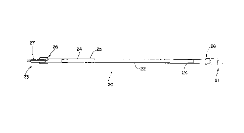
Fig. 4 is a schematic view illustrating the present
invention.

21415g9
CASE 5445
DESCRIPIION OF T~IE PRk;~KRED EMBODIMENT
As shown in Fig. 3, tubes 4 which are located in a
tubesheet 2 (Fig. 1) are expanded through the use of a
known one-step full depth expansion mandrel 10 for those
tubes which are located in a central portion of the
tubesheet 2. For those tubes 4 located near the periphery
of tubesheet 2, a known two-step expandable mandrel 12 is
used to expand the tubes 4 because of the curvature of the
hemispherical head 5 (Fig. 2), encroaches on the probe
insertion area.
The known one-step expansion mandrel 10 has hydraulic
seals 14 at each end of the probe. Mandrels 10 and 12
utilize a calibration collar 13 in conjunction with a
handle 15 and a pressure tube 16 for providing fluid to the
tube 4 for expanding the tube 4 to correspond to a
thickness D of the tubesheet 2.
The two-step expandable mandrel 12 has hydraulic seals
14 spaced apart from each other; and a flexible extension
18, which is a flexible hose, attached at one end of the
probe 12. The two-step expandable mandrel 12 is a half-
length mandrel which is inserted at a primary side 2a of
the tubesheet 2 and is extended through the tube 4 until it
reaches a set position relative to a secondary side 2b of

2144599 - ~
-
CASE 5445
the tubesheet 2. The two-step mandrel 12 allows for half
of the length of the tube 4 to be hydraulically expanded.
After expanding half of tube 4, the half-length mandrel 12
is extracted from the tube 4. A second two-step expandable
mandrel 12 is then inserted into tube 4 at prlmary side 2a
of tubesheet 2 in order to expand the remaining portion of
the tube 4 contained within the tubesheet 2.
It is been estimated that for steam generators,
approximately 20~ of all tubes require a two-step
expansion. Because of this two-step requirement, the
procedure described above using the two-step expandable
mandrel 12 requires a significant amount of labor and cost.
According to the present invention, as shown in Fig.
4, a flexible hydraulic expansion mandrel 20 is used for
all tube ends at all areas of a tubesheet. The mandrel 20
comprises a flexible wire 22, such as a cable or rope,
which is placed within a tube 4 (Fig. 3) for expanding the
tube 4 according to the tubesheet thickness D. A connector
or joint 24, which is steel, connects a hydraulic seal 26
to each end of the flexible wire 22. The connection
between connector 24 and flexible wire 22 is a cable to
steel transition joint 25.
A fluid inlet 27 is provided at a rear end 23 of the
mandrel 20 opposite a front end 21. The fluid provided

~- 2144599
CASE 5445
through fluid inlet 27 is provided between hydraulic seals
26 for expanding the tube 4 (Fig. 3).
While specific embodiments of the invention have been
shown and described in detail to illustrate the application
of the principles of the invention, it will be understood
that the invention may be embodied otherwise without
departing from such principles.

Representative Drawing
A single figure which represents the drawing illustrating the invention.
Administrative Status

2024-08-01:As part of the Next Generation Patents (NGP) transition, the Canadian Patents Database (CPD) now contains a more detailed Event History, which replicates the Event Log of our new back-office solution.

Please note that "Inactive:" events refers to events no longer in use in our new back-office solution.

For a clearer understanding of the status of the application/patent presented on this page, the site Disclaimer , as well as the definitions for Patent , Event History , Maintenance Fee  and Payment History  should be consulted.

Event History

Description Date
Inactive: IPC from MCD 2006-03-11
Time Limit for Reversal Expired 2003-03-14
Letter Sent 2002-03-14
Grant by Issuance 1999-11-16
Inactive: Cover page published 1999-11-15
Inactive: Final fee received 1999-08-19
Pre-grant 1999-08-19
4 1999-03-11
Notice of Allowance is Issued 1999-03-11
Letter Sent 1999-03-11
Inactive: Status info is complete as of Log entry date 1999-03-08
Inactive: Application prosecuted on TS as of Log entry date 1999-03-08
Inactive: Approved for allowance (AFA) 1999-01-18
Application Published (Open to Public Inspection) 1995-09-17
All Requirements for Examination Determined Compliant 1995-03-14
Request for Examination Requirements Determined Compliant 1995-03-14

Abandonment History

There is no abandonment history.

Maintenance Fee

The last payment was received on 1999-03-10

Note : If the full payment has not been received on or before the date indicated, a further fee may be required which may be one of the following

  • the reinstatement fee;
  • the late payment fee; or
  • additional fee to reverse deemed expiry.

Patent fees are adjusted on the 1st of January every year. The amounts above are the current amounts if received by December 31 of the current year.
Please refer to the CIPO Patent Fees web page to see all current fee amounts.

Fee History

Fee Type Anniversary Year Due Date Paid Date
MF (application, 3rd anniv.) - standard 03 1998-03-16 1998-03-06
MF (application, 4th anniv.) - standard 04 1999-03-15 1999-03-10
Final fee - standard 1999-08-19
MF (patent, 5th anniv.) - standard 2000-03-14 2000-02-18
MF (patent, 6th anniv.) - standard 2001-03-14 2001-02-20
Owners on Record

Note: Records showing the ownership history in alphabetical order.

Current Owners on Record
BABCOCK AND WILCOX COMPANY
Past Owners on Record
KEIROUZ DIAB
MARK BLEZARD
Past Owners that do not appear in the "Owners on Record" listing will appear in other documentation within the application.
Documents

To view selected files, please enter reCAPTCHA code :


To view images, click a link in the Document Description column (Temporarily unavailable). To download the documents, select one or more checkboxes in the first column and then click the "Download Selected in PDF format (Zip Archive)" or the "Download Selected as Single PDF" button.

List of published and non-published patent-specific documents on the CPD .

If you have any difficulty accessing content, you can call the Client Service Centre at 1-866-997-1936 or send them an e-mail at CIPO Client Service Centre.

({010=All Documents, 020=As Filed, 030=As Open to Public Inspection, 040=At Issuance, 050=Examination, 060=Incoming Correspondence, 070=Miscellaneous, 080=Outgoing Correspondence, 090=Payment})


Document
Description 
Date
(yyyy-mm-dd) 
Number of pages   Size of Image (KB) 
Abstract 1995-09-16 1 13
Description 1995-09-16 7 189
Drawings 1995-09-16 4 43
Claims 1995-09-16 2 28
Claims 1999-01-05 2 32
Representative drawing 1998-06-11 1 4
Representative drawing 1999-11-07 1 3
Commissioner's Notice - Application Found Allowable 1999-03-10 1 164
Maintenance Fee Notice 2002-04-10 1 179
Correspondence 1999-08-18 1 35
Fees 1999-03-09 1 37
Fees 1998-03-05 1 33
Fees 1997-02-24 1 42
Courtesy - Office Letter 1995-04-27 1 15
Prosecution correspondence 1995-05-15 1 26
Correspondence related to formalities 1996-10-29 1 31
Correspondence related to formalities 1999-08-18 1 36
Examiner Requisition 1998-06-08 1 32
Prosecution correspondence 1998-12-02 2 42
Courtesy - Office Letter 1996-12-08 1 15
Courtesy - Office Letter 1996-12-08 1 18
Correspondence related to formalities 1996-10-29 4 93
Correspondence related to formalities 1995-05-08 1 30