Sélection de la langue

Search

Sommaire du brevet 2144599 

Énoncé de désistement de responsabilité concernant l'information provenant de tiers

Une partie des informations de ce site Web a été fournie par des sources externes. Le gouvernement du Canada n'assume aucune responsabilité concernant la précision, l'actualité ou la fiabilité des informations fournies par les sources externes. Les utilisateurs qui désirent employer cette information devraient consulter directement la source des informations. Le contenu fourni par les sources externes n'est pas assujetti aux exigences sur les langues officielles, la protection des renseignements personnels et l'accessibilité.

Disponibilité de l'Abrégé et des Revendications

L'apparition de différences dans le texte et l'image des Revendications et de l'Abrégé dépend du moment auquel le document est publié. Les textes des Revendications et de l'Abrégé sont affichés :

  • lorsque la demande peut être examinée par le public;
  • lorsque le brevet est émis (délivrance).
(12) Brevet: (11) CA 2144599
(54) Titre français: MANDRIN FLEXIBLE A EXPANSION HYDRAULIQUE
(54) Titre anglais: FLEXIBLE HYDRAULIC EXPANSION MANDREL
Statut: Périmé et au-delà du délai pour l’annulation
Données bibliographiques
(51) Classification internationale des brevets (CIB):
  • B21D 41/02 (2006.01)
  • B21D 9/00 (2006.01)
  • B21D 39/20 (2006.01)
(72) Inventeurs :
  • BLEZARD, MARK (Canada)
  • DIAB, KEIROUZ (Canada)
(73) Titulaires :
  • BABCOCK AND WILCOX COMPANY
(71) Demandeurs :
  • BABCOCK AND WILCOX COMPANY (Etats-Unis d'Amérique)
(74) Agent: GEORGE A. ROLSTONROLSTON, GEORGE A.
(74) Co-agent:
(45) Délivré: 1999-11-16
(22) Date de dépôt: 1995-03-14
(41) Mise à la disponibilité du public: 1995-09-17
Requête d'examen: 1995-03-14
Licence disponible: S.O.
Cédé au domaine public: S.O.
(25) Langue des documents déposés: Anglais

Traité de coopération en matière de brevets (PCT): Non

(30) Données de priorité de la demande:
Numéro de la demande Pays / territoire Date
08/214,342 (Etats-Unis d'Amérique) 1994-03-16

Abrégés

Abrégé anglais


A flexible mandrel for expanding a tube in a tubesheet
comprises a length of flexible wire which is placed within
a tube. A hydraulic seal is located at each end of the
length of flexible wire for sealing a section of the tube
and is connected to the flexible wire by a connector. A
fluid inlet is provided at the rear end of the mandrel for
providing fluid to the mandrel between the sealed section
of the tube.

Revendications

Note : Les revendications sont présentées dans la langue officielle dans laquelle elles ont été soumises.


The embodiments of the invention in which an exclusive property or privilege
is claimed are defined as follows:
1. A flexible mandrel for expanding a tube in a tube sheet of a
steam generator, the mandrel comprising:
a length of flexible wire for being placed within a tube inside a
tube inside a tube sheet of a steam generator;
sealing means at each end of the length of flexible wire for
sealing a section of the tube;
a connector at each end of said flexibile wire for connecting the
sealing means to the length of flexibile wire; and
a single fluid inlet at one end of the mandrel for providing fluid
into the section of the tube for sealing and expanding the tube within the
tube
sheet.
2. The mandrel according to claim 1, wherein the flexible wire is a
cable.
3. The mandrel according to claim 1, wherein the flexible wire is a
wire rope.
8

4. The mandrel according to claim 1, wherein the sealing means
comprises a hydraulic seal.
5. The mandrel according to claim 1, wherein the connector is made
of steel.
6. The mandrel according to claim 1, wherein the one end of the
mandrel is a rear end of the mandrel.
9

Description

Note : Les descriptions sont présentées dans la langue officielle dans laquelle elles ont été soumises.

~ 21~599
CASE 5445
FLEXIBLE ~YDRAULIC EXPANSION MANDREL
BACKGROUND OF THE INVENTION
1. Field of the Invention
The present invention relates, in general, to heat
exchanger tubes and, in particular, to a new and useful
device for hydraulically expanding a tube within a
tubesheet.
2 . Description of the Related Art
In the power plant field, a tubesheet is used for a
nuclear steam generator, heat exchanger or a similar
component that houses several thousand tube ends. The
tubesheet has numerous holes previously drilled in it which
allows for each tube end to be inserted therethrough. The
tube ends are welded to the tubesheet and circumferentially
expanded into the tubesheet holes through virtually the
full thickness of the tubesheet. This process is commonly
referred to as full depth expansion.
The expansion of the tube ends can be achieved through
mechanical or hydraulic processes. When manufacturing
components for a nuclear steam generator, it is pre~erable

2144599
CASE 5445
that hydraulic expansion be used. Each tube is
hydraulically expanded into its tube hole after welding so
that the expansion closes the crevice between the tube and
the hole in order to avoid a potential corrosion site.
Hydraulic expansion is the recommended method for
nuclear steam generators because it produces less residual
stress in the tube and reduces the potential for stress
corrosion cracking compared to other expansion methods.
The tube is expanded by inserting a probe. The expansion
probe has a seal positioned at each end of the expansion
zone. Distilled water at 35,000 psi (2413 bar) is pumped
through the probe which expands the tube and seals it
against the tube hole.
The expansion probe must be carefully positioned with
respect to the secondary face of the tubesheet. If the
probe is positioned beyond the face, then unacceptable tube
deformation could occur. If the probe is too far inside
the tube hole, an unacceptably long crevice could possibly
result. Therefore, the tubesheet thickness variation is
measured and the probe length is adjusted to ensure proper
positioning.
In the central region of a tubesheet, the tubes are
expanded using a one-step full depth hydraulic expansion
mandrel. For those tubes located at the outer periphery of

`_ 21g4599
CASE 5445
the tubesheet, a two-step hydraulic expansion technique is
used to expand the tube ends due to possible interference
with the hemispherical head.
Presently, there is no known device which can be
utilized to expand a tube end over the -entire tubesheet
including peripheral areas.
SI~MMARY OF T~IE INVENTION
The present invention pertains to the expansion of
tube ends extended through tubesheets.
lo The present invention is a mandrel for expanding a
tube end comprising a length of flexible wire which is
placed within a tube end. Hydraulic seals are located at
each end of the length of flexible wire for sealing a
section of the tube end. Each hydraulic seal is connected
to the flexible wire by a steel connector. A hydraulic
fluid inlet is provided at one end of the mandrel for
providing fluid between the seals for expanding the section
of tube.
It is an object of the present invention to provide a
mandrel for expanding a tube end which is easy to use,
simple to manufacture and rugged in construction.
The various features of novelty which characterize the
invention are pointed out with particularity in the claims

21~4599
`~
CASE 5445
annexed to and forming a part of this disclosure. For a
better understanding of the invention, its operating
advantages and specific objects attained by its uses,
reference is made to the accompanying drawings and
descriptive matter in which a preferred embodiment of the
invention is illustrated.
BRIEF DESCRIPTION OF T~E DRAVVINGS
In the drawings:
Fig. 1 is a plan view of a tubesheet;
Fig. 2 is a schematic view illustrating a hemispherical
head;
Fig. 3 is a schematic view illustrating a tubesheet
having a known one-step full depth expansion
mandrel and a known two-step expansion mandrel;
and
Fig. 4 is a schematic view illustrating the present
invention.

21415g9
CASE 5445
DESCRIPIION OF T~IE PRk;~KRED EMBODIMENT
As shown in Fig. 3, tubes 4 which are located in a
tubesheet 2 (Fig. 1) are expanded through the use of a
known one-step full depth expansion mandrel 10 for those
tubes which are located in a central portion of the
tubesheet 2. For those tubes 4 located near the periphery
of tubesheet 2, a known two-step expandable mandrel 12 is
used to expand the tubes 4 because of the curvature of the
hemispherical head 5 (Fig. 2), encroaches on the probe
insertion area.
The known one-step expansion mandrel 10 has hydraulic
seals 14 at each end of the probe. Mandrels 10 and 12
utilize a calibration collar 13 in conjunction with a
handle 15 and a pressure tube 16 for providing fluid to the
tube 4 for expanding the tube 4 to correspond to a
thickness D of the tubesheet 2.
The two-step expandable mandrel 12 has hydraulic seals
14 spaced apart from each other; and a flexible extension
18, which is a flexible hose, attached at one end of the
probe 12. The two-step expandable mandrel 12 is a half-
length mandrel which is inserted at a primary side 2a of
the tubesheet 2 and is extended through the tube 4 until it
reaches a set position relative to a secondary side 2b of

2144599 - ~
-
CASE 5445
the tubesheet 2. The two-step mandrel 12 allows for half
of the length of the tube 4 to be hydraulically expanded.
After expanding half of tube 4, the half-length mandrel 12
is extracted from the tube 4. A second two-step expandable
mandrel 12 is then inserted into tube 4 at prlmary side 2a
of tubesheet 2 in order to expand the remaining portion of
the tube 4 contained within the tubesheet 2.
It is been estimated that for steam generators,
approximately 20~ of all tubes require a two-step
expansion. Because of this two-step requirement, the
procedure described above using the two-step expandable
mandrel 12 requires a significant amount of labor and cost.
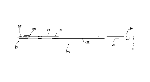
According to the present invention, as shown in Fig.
4, a flexible hydraulic expansion mandrel 20 is used for
all tube ends at all areas of a tubesheet. The mandrel 20
comprises a flexible wire 22, such as a cable or rope,
which is placed within a tube 4 (Fig. 3) for expanding the
tube 4 according to the tubesheet thickness D. A connector
or joint 24, which is steel, connects a hydraulic seal 26
to each end of the flexible wire 22. The connection
between connector 24 and flexible wire 22 is a cable to
steel transition joint 25.
A fluid inlet 27 is provided at a rear end 23 of the
mandrel 20 opposite a front end 21. The fluid provided

~- 2144599
CASE 5445
through fluid inlet 27 is provided between hydraulic seals
26 for expanding the tube 4 (Fig. 3).
While specific embodiments of the invention have been
shown and described in detail to illustrate the application
of the principles of the invention, it will be understood
that the invention may be embodied otherwise without
departing from such principles.

Dessin représentatif
Une figure unique qui représente un dessin illustrant l'invention.
États administratifs

2024-08-01 : Dans le cadre de la transition vers les Brevets de nouvelle génération (BNG), la base de données sur les brevets canadiens (BDBC) contient désormais un Historique d'événement plus détaillé, qui reproduit le Journal des événements de notre nouvelle solution interne.

Veuillez noter que les événements débutant par « Inactive : » se réfèrent à des événements qui ne sont plus utilisés dans notre nouvelle solution interne.

Pour une meilleure compréhension de l'état de la demande ou brevet qui figure sur cette page, la rubrique Mise en garde , et les descriptions de Brevet , Historique d'événement , Taxes périodiques et Historique des paiements devraient être consultées.

Historique d'événement

Description Date
Inactive : CIB de MCD 2006-03-11
Le délai pour l'annulation est expiré 2003-03-14
Lettre envoyée 2002-03-14
Accordé par délivrance 1999-11-16
Inactive : Page couverture publiée 1999-11-15
Inactive : Taxe finale reçue 1999-08-19
Préoctroi 1999-08-19
month 1999-03-11
Un avis d'acceptation est envoyé 1999-03-11
Lettre envoyée 1999-03-11
Inactive : Renseign. sur l'état - Complets dès date d'ent. journ. 1999-03-08
Inactive : Dem. traitée sur TS dès date d'ent. journal 1999-03-08
Inactive : Approuvée aux fins d'acceptation (AFA) 1999-01-18
Demande publiée (accessible au public) 1995-09-17
Toutes les exigences pour l'examen - jugée conforme 1995-03-14
Exigences pour une requête d'examen - jugée conforme 1995-03-14

Historique d'abandonnement

Il n'y a pas d'historique d'abandonnement

Taxes périodiques

Le dernier paiement a été reçu le 1999-03-10

Avis : Si le paiement en totalité n'a pas été reçu au plus tard à la date indiquée, une taxe supplémentaire peut être imposée, soit une des taxes suivantes :

  • taxe de rétablissement ;
  • taxe pour paiement en souffrance ; ou
  • taxe additionnelle pour le renversement d'une péremption réputée.

Les taxes sur les brevets sont ajustées au 1er janvier de chaque année. Les montants ci-dessus sont les montants actuels s'ils sont reçus au plus tard le 31 décembre de l'année en cours.
Veuillez vous référer à la page web des taxes sur les brevets de l'OPIC pour voir tous les montants actuels des taxes.

Historique des taxes

Type de taxes Anniversaire Échéance Date payée
TM (demande, 3e anniv.) - générale 03 1998-03-16 1998-03-06
TM (demande, 4e anniv.) - générale 04 1999-03-15 1999-03-10
Taxe finale - générale 1999-08-19
TM (brevet, 5e anniv.) - générale 2000-03-14 2000-02-18
TM (brevet, 6e anniv.) - générale 2001-03-14 2001-02-20
Titulaires au dossier

Les titulaires actuels et antérieures au dossier sont affichés en ordre alphabétique.

Titulaires actuels au dossier
BABCOCK AND WILCOX COMPANY
Titulaires antérieures au dossier
KEIROUZ DIAB
MARK BLEZARD
Les propriétaires antérieurs qui ne figurent pas dans la liste des « Propriétaires au dossier » apparaîtront dans d'autres documents au dossier.
Documents

Pour visionner les fichiers sélectionnés, entrer le code reCAPTCHA :


Pour visualiser une image, cliquer sur un lien dans la colonne description du document (Temporairement non-disponible). Pour télécharger l'image (les images), cliquer l'une ou plusieurs cases à cocher dans la première colonne et ensuite cliquer sur le bouton "Télécharger sélection en format PDF (archive Zip)" ou le bouton "Télécharger sélection (en un fichier PDF fusionné)".

Liste des documents de brevet publiés et non publiés sur la BDBC .

Si vous avez des difficultés à accéder au contenu, veuillez communiquer avec le Centre de services à la clientèle au 1-866-997-1936, ou envoyer un courriel au Centre de service à la clientèle de l'OPIC.

({010=Tous les documents, 020=Au moment du dépôt, 030=Au moment de la mise à la disponibilité du public, 040=À la délivrance, 050=Examen, 060=Correspondance reçue, 070=Divers, 080=Correspondance envoyée, 090=Paiement})


Description du
Document 
Date
(aaaa-mm-jj) 
Nombre de pages   Taille de l'image (Ko) 
Abrégé 1995-09-16 1 13
Description 1995-09-16 7 189
Dessins 1995-09-16 4 43
Revendications 1995-09-16 2 28
Revendications 1999-01-05 2 32
Dessin représentatif 1998-06-11 1 4
Dessin représentatif 1999-11-07 1 3
Avis du commissaire - Demande jugée acceptable 1999-03-10 1 164
Avis concernant la taxe de maintien 2002-04-10 1 179
Correspondance 1999-08-18 1 35
Taxes 1999-03-09 1 37
Taxes 1998-03-05 1 33
Taxes 1997-02-24 1 42
Courtoisie - Lettre du bureau 1995-04-27 1 15
Correspondance de la poursuite 1995-05-15 1 26
Correspondance reliée aux formalités 1996-10-29 1 31
Correspondance reliée aux formalités 1999-08-18 1 36
Demande de l'examinateur 1998-06-08 1 32
Correspondance de la poursuite 1998-12-02 2 42
Courtoisie - Lettre du bureau 1996-12-08 1 15
Courtoisie - Lettre du bureau 1996-12-08 1 18
Correspondance reliée aux formalités 1996-10-29 4 93
Correspondance reliée aux formalités 1995-05-08 1 30