Note: Descriptions are shown in the official language in which they were submitted.
APPARATUS AND METHOD FOR RADIO COMMUNICATION
BACKGROUND OF THE INVENTION
(1) Field of the Invention
The present invention relates to an apparatus and method
for radio communication in a radio network, and particularly
to such an apparatus and method applicable to a distributed
environment, i.e. a network which has a distributed topology.
(2) Description of the Related Art
Radio networks with the use of radio wave or infrared
light have been in great demand these days because they require
no communication cables. Radio terminals can intercommunicate
from any site within their communication ranges, and be used
on the move when they are reduced to portable.
However, radio networks often suffer from so called
.l5 "Hidden Terminal Problem" which does not affect wired networks
and is caused by a radio terminal outside their communication
ranges.
FIG. 1 is an illustration to be used to explain a Hidden
Terminal Problem (hereinafter HTP).
:?0 A, B, and C are radio terminals, and the circles represent
respective communication ranges. When terminal A is
communicating with terminal B, terminal C is getting no signal
from terminal A. Consequently, terminal C might start to
communicate with terminal B, without knowing the communications
l5 between terminals A and B. If terminal B i:; thus communicated
1
2144-66fi
from both terminals A and C, the communication carried out so
far between terminals A and B ends up i.n vain. Thus, the
occurrence of HTP requires .retransmission, reducing data
transmission throughput in radio networks.
In order to solve the HTP, various radio network
communication schemes have been proposed as follows.
<CSMA/CA + Ack>
A communication scheme called CSMA/CA + Ack ( Carrier Sense
Multiple Access with Collision Avoidance plus Acknowledgement)
has been proposed by W. Diepstraten in "A Distributed Access
Protocol Proposal Supporting Time Bounded Service" (IEEE
Working Group Paper 802.11-93/70).
Although this scheme is not directly concerned with the
solution of HTP, it is a basic communication scheme in networks
and referred to later in the explanation of communication
schemes.
Generally, multiple accesses in a network can be realized
based on a MAC ( Medium Access Control ) layer protocol . The
CSMA/CA + Ack is a MAC layer protocol based on CSMA/CA which
is widely used as a MAC layer protocol in a radio network. The
CSMA/CA + Ack has a function for <~cknowledgement and
retransmission of frames at a MAC layer level, in addition to
the functions of CSMA/CA. The CSMA/CA is more suitable to
radio communications than CSMA/CD (CSMA with Collision
Detection) which is widely used as the MAC layer protocol in
2
214466
cable networks.
According to the CSMA/CA + Ack, a first terminal which
is ready to transmit data makes, sure that the transmission path
has no signal for a predetermined gap time period, and then
starts the data transmission in,frames to~ a second terminal.
The second terminal, which has received the frames returns a
confirming frame to the first terminal in order to report the
successful reception of the frames, after having made sure that
the transmission path has no signal for a predetermined gap
time period.
Although the use of the confirming frames has improved the
reliability of the data transmission, this scheme presupposes
that a signal transmitted by any of terminals is distributed
to all the terminals in the network, which does not insist on
solving the HTP.
<K. Biba>
K. Biba has proposed a scheme of solving HTP in "A hybrid
Wireless MAC Protocol Supporting Asynchronous and Synchronous
MSDU Delivery Service" (IEEE Working Group Paper 802.11-
91/92). In order to avoid HTP, a transmilaing terminal and a
receiving terminal establishes a connection every time a frame
is transmitted, and informs the other terminals of a time
period during which the transmission path is occupied in
establishing a connection.
According to this scheme, a transmitting terminal sends
3
21446 fib
an RTS (request to send) frame prior to a data transmission,
and a receiving terminal returns a CTS (C:Lear to Send) frame
to report the reception of, the RTS frame. Then, the
transmitting terminal sends data in frames, and the receiving
terminal returns an ACK frame to report the receipt of the
frames. An RTS frame carries the length of data to be
transmitted, and a CTS frame carries the length of data to be
received. Prior to the transmission of RTS frames and CTS
frames, the condition of the transmission path is checked with
CSMA. The terminals other than the destination of an RTS frame
check the length of the data carried in the frame and refrain
from accessing the transmission path until the transmission and
acknowledgement of the data is completed. In the same manner,
the terminals other than the destination of a CTS frame do not
access the transmission path until the: transmission and
acknowledgement of the data is completed. This is how HTP is
solved in this system.
However, a connection must be established per frame, so
that the efficiency of data transmission is decreased when
large data being divided into a plurality of frames are
transmitted.
For another problem, the transmission of an RTS (or CTS)
frame may be sometimes unsuccessful because of a collision.
In that case, a terminal which successfully received the RTS
(or CTS) frame must be deprived of the access to the
transmission path in vain for the time period corresponding to
4
214~.sss
the unexecuted data transmission.
For further another problem, there is a possibility that
a terminal which moved into ,the transmission range of the
receiving terminal starts another data transmission without
knowing the preceding data transmission. Thus, HTP resulting
from a terminal's movement cannot be solved.
<Japanese Laid-open Patent Application No. 5-260051>
The scheme proposed in Japanese Laid-open Patent
Application No. 5-260051 is used in a system composed of a
plurality of terminals, and a base station which communicates
with all the terminals. An available frequency band is divided
into a message channel, an up link channel, and a down link
channel.
A terminal which is ready to transmit data checks the
presence or absence of a channel tone, and in the case of its
absence, transmits a channel tone on they up link channel.
Detecting the channel tone, the base station transmits the
same channel tone on the down link channel. Detecting the
return of the channel tone, the terminal starts data
:ZO transmission.
This scheme requires the base station to solve HTP, so
that in case that the base station is out: of order, all the
terminals in the network becomes unable to communicate,
deteriorating the reliability of the entire network.
5
2144~6~
<U.S.P. No. 4409687>
The communication scheme disclosed ire U.S.P. No. 4409687
can use a plurality of channels assigned to different
frequencies, and is used in a system composed of a plurality
of terminals and a base station. P~, terminal in the
transmission mode scans all the channels prior to a data
transmission, and if a channel in the idle state is found, the
terminal transmits a busy tone on the channel and further
transmits a predetermined group tone. Receiving the busy tone
from the terminal, the base station transmits the busy tone on
the channel, and further repeats the group tone. A terminal
in the reception mode scans all the channels, and establishes
a connection with the transmitter in response to the reception
of the predetermined group tone.
This scheme can solve HTP; however, :it still requires a
base station (repeater), and as a result 'this system suffers
from the same problems as the above mentioned Japanese Laid-
open Patent Application No. 5-260051.
<U.S.P. Nos. 4360927 and 4658435>
U.S.P. Nos. 4360927 and 4658435 have also disclose
communication schemes capable of solving the HTP and of using
a plurality of channels; however, these schemes require a base
station, suffering the same problems as mentioned above.
SUMMARY OF THE INVENTION
6
21446 (i fi
The object of the present invention is to provide an
apparatus and methad of radio communication capable of avoiding
HTP in a radio network and applicable: to a distributed
environment having no base station, thereby realizing a high
reliability and high transmission efficiency.
The object can be achieved by a radio communication method
for transmitting and receiving data between a first terminal
and a second terminal. The method comprises the following
steps:
establishing a connection between thE: first terminal and
the second terminal when the first terminal and the second
terminal have detected that a signal has not been transmitted
on a predetermined channel; and
starting data communications between the first terminal
and the second terminal which have established the connection,
and transmitting a predetermined signal on the predetermined
channel from both the first terminal and the second terminal
throughout the data communications.
The connection establishment step may comprise the
following sub steps:
detecting a presence or absence of they signal transmitted
on the predetermined channel, by the firsi~ terminal;
transmitting a first control signal from the first
terminal to the second terminal in a case where the absence
of the signal transmitted on the predetermined channel has
been detected by the first terminal;
7
214~sss
detecting a presence or absence of the signal transmitted
on the predetermined channel, by the second terminal, when the
second terminal has received the first control signal;
transmitting a second control signal from the second
terminal to the first terminal in a case where the absence of
the signal transmitted on the predetermined channel has been
detected by the second terminal; and
receiving the second control signal b;y the first terminal.
Each of the first terminal and the second terminal may
be assigned a control channel provided for connection
establishment and a data channel provided for data
transmission, and the predetermined channE:l may be the control
channel.
According to the above construction, both a transmitting
terminal and a receiving terminal transmit a busy tone on a
control channel while they are in process of data
communication. Another terminal which is ready to transmit
data is supposed to check before data transmission that there
is no busy tone transmitted, so that the; terminal can start
communication only when no terminal which is inside the
checking terminal's communication range is in a communication
process. As a result, HTP can be prevented.
Furthermore, the HTP is prevented by transmitting a busy
tone, so that a highly reliable radio network can be
constructed in a distributed environment 'which is dispensable
with a base station.
8
2144666
Each of the first terminal and the second terminal
may be assigned a data channel provided for connection
establishment and d~~ta transmission and a control channel,
and the predetermined channel may be the control channel.
According to -the above-mentioned construction, the
control channel is used only for the transmission of busy
tones. Consequently, the band width for the control
channel can be narrower, thereby making a good use of
frequency band width..
The connection establishment step may further
comprise the sub step of starting a transmission of the
predetermined signal on the control channel from the
second terminal, at_ a predetermined time point after a
completion of the ~>ub step of detecting the presence or
absence of the signal transmitted on the control channel
by the second terminal.
The connection establishment step may further
comprise the sub step of transmitting the predetermined
signal on the control channel from the first terminal
concurrently with ,~ transmission of the first control
signal from the first terminal.
In a further aspect, the present invention provides a
radio communication method for transmitting and receiving
data between a first terminal and a second terminal using
a control channel and a data channel, said method
comprising the steps of: a connection establishment phase
which includes: a first check step in which the first
terminal checks whether a busy tone, a first control
signal, and a second control signal are all absent on the
control channel, wherein the first control signal conveys
a connection request and the second control. signa:L conveys
an acknowledgment oi= the connection request; a connection
9
2144666
request step in which the first terminal transmits the
first control signal to the second terminal via the
control channel when the first terminal confirms that the
busy tone, the first control signal, and the second
control signal are all absent on the cont=rol channel; a
second check step in which the second. terminal, on
receiving the first control signal from the first
terminal, checks whether the busy tone, the first control
signal, and the second control signal are all absent on
the control channel; a connection acknowledgment step in
which the second terminal transmits the second control
signal to the first terminal via the control channel when
the second terminal confirms that the busy tone, the first
control signal, and the second control signal are all
absent on the r_ont_ol channel, then starts continuously
transmitting the buoy tone to the control channel; and a
busy tone transmission step in which the first terminal,
on receiving the second control signal. from the second
terminal, starts continuously transmitting the busy tone
to the control channel; and a data communication phase
which includes : a data communication step in which a data
communication betwec=n the first terminal and the second
terminal via the data channel starts;' and a data
communication end step in which the data communication
between the first germinal and the second terminal ends
and the first terminal and the second terminal stop
transmitting the busy tone.
In a further aspect, the present invention provides a
radio communication method for transmitting and receiving
data between a first terminal and a second terminal using
a control channel and a data channel, said method
comprising the steps of: a connection establishment phase
9a
2144666
which includes: a first check step in which the first
terminal checks whether a busy tone is absent. on the
control channel; a connection request step in which the
first terminal transmits a first control signal to the
second terminal via the data channel when the first
terminal confirms that the busy tone is absent, on the
control channel, whe rein the first control signal conveys
a connection request; a second check step in which the
second terminal, on receiving the first control signal
from the first terminal, checks whether the busy tone is
absent on the contrc>1 channel; a connection acknowledgment
step in which the second terminal transmits a second
control signal to the first terminal aria the data channel
when the second terminal confirms that the busy tone is
absent on the contr~~l channel, wherein the second control
signal conveys an acknowledgment of the connection
request, then starts continuously transmitting the busy
tone to the control channel; and a busy tone transmission
step in which the first terminal, on receiving the second
control signal from the second terminal, starts
continuously transmitting the busy tone to the control
channel; and a data communication phase which includes: a
data communication step in which a data communication
between the first terminal and the second t~ermina:l via the
data channel starts;' and a data communication end step in
which the data corrununication between the first terminal
and the second terminal ends and the first terminal and
the second terminal stop transmitting the busy tone.
In a still further aspect, the present invention
provides a radio con~ununication method for t: ransmitting and
receiving data between a first terminal and a second
terminal, wherein each terminal may not be able to hear
9b
2144666
signals sent by all other terminals, said method
comprising the steps of: establishing a connection between
the first terminal and the second terminal when the first
terminal and the second terminal have detected that any
signal has not been transmitted on a predetermined
channel, wherein each of the first terminal and the second
terminal is assigned a data channel provided for
connection establishment and data transmission and a
control channel, said predetermined channel being the
control channel, the connection establishment step
comprising the stepa of: detecting a presence or_ absence
of said signal transmitted on said predetermined channel,
by the first terminal; transmitting a first: cOrltrol signal
from the first terminal to the second terminal i.n a case
where the absence of said signal transmitted on said
predetermined channel has been detected by the first
terminal; detecting a presence or absence of said signal
transmitted on said predetermined channel, by tyre second
terminal, when the aecond terminal has received the first
control signal; starting a transmission of said signal on
the control channel from the second t:ermina:l, at a
predetermined time point after a completion of_ detecting
the presence or absence of said signal transmitted on the
control channel by the second terminal; transmitting a
second control signal from the second terminal to the
first terminal in a case where the absence of said signal
transmitted on said predetermined channel has been
detected by the second terminal; receiving the second
control signal by the first terminal; and transmitting
said signal on t:he control channel from the first terminal
concurrently with a transmission of the first control
signal from the first terminal; and starting data
;.'r~ 9 c
2144666
communications between the first terminal and the second
terminal which have established the connection, and
simultaneously transmitting a predetermined signal on said
predetermined channel from both the first terminal and the
second terminal and continuing to transmit the
predetermined signal throughout the data conununiCations.
According to t:ne above-mentioned construction, busy
tones are transmitted on the control channel also in the
connection establishment step. ConsEequentl:y, data
communication in a connection establishment step is less
affected by another terminal, establishing a connection in
a shorter time.
The object can be achieved by a radio communication
apparatus for transmitting and receiving data to and from a
9d
2m4sss
desired radio communication apparatus.
The radio communication apparatus comprises the following
units:
a connection establishment unit for detecting a presence
or absence of a signal transmitted on a predetermined channel,
and for establishing a connection with the desired radio
communication apparatus when the absence of the signal
transmitted on the predetermined channel has been detected;
a data communication unit for starting data communications
with the desired radio communication apparatus, responding to
the connection establishment; and
a signal transmission unit for continuing a transmission
of a predetermined signal on the predetermined channel from
the radio communication apparatus and 'the desired radio
7.5 communication apparatus throughout the data communications.
The connection establishment unit may comprise the
following units:
a detection unit for detecting a presence or absence of
the signal transmitted on the predetermined channel;
ZO a control signal transmission unit for selectively
transmitting one of a first control signal and a second control
signal;
a control signal reception unit for receiving the first
control signal and the second control signal; and
25 a control unit for controlling the control signal
transmission unit to transmit the first control signal when
2144~G6
the detection unit has detected the absssnce of the signal
transmitted on the predetermined channel in a case where the
radio communication apparatus,is a transmitting terminal, and
for, in a case where the radio communication apparatus is a
receiving terminal, controlling the control signal transmission
unit to transmit the second control signal to the desired radio
communication apparatus after the first control signal has been
received by the control signal reception unit and the signal
has been detected to be absent on the predetermined channel
LO by the detection unit.
The control signal transmission unit may transmit the first
control signal and the second control signal on a control
channel, the data communication unit may perform the data
communications on a data channel provided apart from the
control channel, and the predetermined channel may be the
control channel.
The control signal transmission unit may transmit the
first control signal and the second control. signal on the data
channel, the data communication unit may perform data
communications on the data channel, and the predetermined
channel may be a control channel provided apart from the data
channel.
The control unit may further comprise t:he following units:
a receiving terminal signal transmission control unit for
:Z5 controlling the signal transmission unit to start a
transmission of the predetermined signal on the control channel
11
2144666
at a predetermined time point after a de tectio:n of the
absence of the signal transmitted on the control channel
and before a commencement of the data communications, in a
case the radio corrununication apparatus has received the
first control signal.
The control unit may further comprise the following
units:
a transmitting terminal signal transmission control
unit for controlling the signal transmission unit to
continue the transmission of the predetermined signal on
the control channel while the control signal transmission
unit is transmitting the first control signal.
In a still further aspect, the present invention
provides a radio communication apparatus for transmitting
and receiving data to and from a desired radio
communication apparatus using a control channel and a data
channel, said radio communica n on apparatus comprising: a
connection establishment means which includes: a
connection request unit for checking whether a busy tone,
a first control signal conveying a connection .request, and
a second control signal conveying an acknowledgment of the
connection request are all absent on the control channel,
then on confirming an absence of the signa7_s, transmitting
the first control signal to the desired radio
communication apparatus via the control channel; a
connection acknowledgment unit which, on receiving a first
control signal from the desired radio communication
apparatus, checks whether the busy tone, the f_Lrst control
signal, and the second control signal. are all absent on
the control channel, then on confirming an absence of the
signals, transmits the second control signal to the
desired radio communication apparatus via the control
12
2144666
channel, and starts continuously transmitting the busy
tone to the control channel; a busy tone transmission unit
which, on receivin0 a second control signal from the
desired radio communication apparatus, starts ~~ontinuously
transmitting the buoy tone to the control channel; and a
data communication means which includes: a data
communication unit for performing a data communication
using the data channel after either of the connection
acknowledgment unit and the busy tone transmission unit
starts transmitting the busy tone; a data communication
end unit for ending the data communication and stopping
transmitting the busy tone.
In a further a~:pect, the present invention provides a
radio communication apparatus for transmitting and
receiving data to and from a desired radio communication
apparatus using a cc>ntrol channel and a data channel, said
radio communication apparatus comprising: a connection
establishment means which includes: a connection request
unit for checking whether a busy tone is absent on the
control channel, then on confirming an absence of the busy
tone, transmitting a first control signal conveying a
connection request to the desired radio communication
apparatus via the data channel; a connection
acknowledgment unit which, on receiving a first. control
signal from the desired radio communication apparatus,
checks whether the busy tone .is absent on the control
channel, then on confi..rming an absen~~e of the busy tone,
transmits a second control signal conveying an
acknowledgment of the connection request to the desired
radio communication apparatus via the dat:a channel, and
starts continuously transmitting the busy tone to the
control channel; a busy tone transmission unit which, on
12a
". "
2144666
receiving a second control signal from the desired radio
communication apparatus, starts continuously transmitting
the busy tone to t:he control channel; and a data
communication means which includes: a data communication
unit for performing a data communication using the data
channel after either of the connection acknowledgment unit
and the busy tone transmission unit starts transmitting
the busy tone; and a data communication end unit for
ending the data communication and stopping transmitting
the busy tone.
In a still further aspect, the present invention
provides a radio communication apparatus for transmitting
and receiving data to and from a desired radio
communication apparatus, wherein each radio communication
apparatus may not be able to hear signals sent from all
other apparatus, the radio communication apparatus
comprising: a connecaion establishment means for detecting
a presence or absence of any signal transmitt:ed on a
predetermined channel, and for establishing a connection
with said desired radio communication apparatus when the
absence of said signal transmitted on said predetermined
channel has been detected; a data communication means for
starting data communications with said desired radio
communication apparatus, responding to the connection
establishment; and a signal transmission means for
transmitting simultaneously with the data, a predetermined
signal on said predetermined channel from both t:he radio
communication apparatus and said desired radio
communication apparatus and continuing to transmit the
predetermined signa_L throughout the data communications;
wherein said connection establishment means comprises: a
detection means for detecting a presence or absence of
12b
2144666
said signal transmitted on said predetermined channel; a
control signal transmission means for selectively
transmitting one of a first control signal and a second
control signal; a control signal reception means for
receiving the first control signal and the second control
signal; and a control means for controlling said control
signal transmission means to transmit the first: control
signal when said detection means has detected the absence
of said signal transmitted on said predetermined channel
in a case where the radio communication apparatus is a
transmitting terminal, and for, in a case where the radio
communication apparatus is a receiving terminal,
controlling said control signal transmission means to
transmit the second control signal to said desired radio
communication apparatus after the first control signal has
been received by said control signal reception means and
said signal has been detected to be absent on said
predetermined channel by said detection means, the control
means comprising: a receiving terminal signal transmission
control means for controlling the signal transmission
means to start a transmission of the predetermined signal
on a control channel. at a predetermined time point after a
detection of the absence of said signal transmitted on the
control channel and before a commencement of the data
communications, in a case the radio communication
apparatus has received the first control signal; and a
transmitting terminal signal transmission control means
for controlling said signal transmission means to continue
the transmission of the predet.erm.ined signal on the
control channel while said control signal transmission
means is transmitting the first control signal; wherein
said control signal transmission means transmits the first
,a;~,, 12 c
2144666
control signal and the second control signal on the data
channel, said data communication means performs data
communications on the data channel, and said predetermined
channel is a control channel provided apart from the data
channel.
According to these constructions, the same effects as
the above mentioned method can be obtained.
BRIEF DESCRIPTION Of THE DRAWINGS
These and other objects, advantages and features of
the invention will become apparent from the following
description thereof taken in conjunction with the
accompanying drawings which illustrate a specific
embodiment of the invention. In the drawings:-
FIG. 1 is an illustration to be used to explain a
HTP.
FIG. 2 shows the types of frames transmitted and
received between two terminals in the first embodiment of
the present invention.
FIGS. 3A-3F show the formats of these frames of FIG.
2.
FIG. 4 shows the construction of the radio
communication apparatus of the first embodiment.
i~~
12d
21~.4~666
FIG. 5 shows the detailed construction of the MAC unit 3
of the first embodiment.
FIGS. 6A and 6B show the Constructions of the modem 4 for
the data channel and the modem 5 for the. busy tone channel
respectively.
FIG. 7 is a flowchart showing the overall operations of
the radio communication apparatus of the first embodiment.
FIG. 8 is a flowchart showing the data transmission
operation of the radio communication apparatus of the first
embodiment.
FIG. 9 is a flowchart showing the data reception operation
of the radio communication apparatus of the first embodiment.
FIG. 10 is a graph showing the results of a numerical
simulation of the throughput property of the radio
communication apparatus of the first embodiment.
FIG. 11 is a table showing the average path loss in the
case that HTP is present, which is used to simulate the
throughput property of the radio communication apparatus of the
first embodiment.
FIG. 12 is a block diagram showing the detailed
construction of the MAC unit 3 of the second embodiment.
FIG. 13 is a block diagram showing the construction of the
modem 5 for the busy tone channel of the radio communication
apparatus of the second embodiment.
FIG. 14 is a flowchart showing the overall operation of
the radio communication apparatus of the second embodiment.
13
m4~-sss
FIG. 15 is a flowchart showing the: data transmission
operation of the radio communication apparatus of the second
embodiment.
FIG. 16 is a flowchart showing ithe data reception
operation of the radio communication apparatus of the second
embodiment.
FIG. 17 is a flowchart depicting the RCON frame
transmission operation of the radio communication apparatus of
the third embodiment.
FIG. 18 is a flowchart depicting a CCON frame transmission
operation of the radio communication apparatus of the third
embodiment.
DESCRIPTION OF THE PREFERRED EMBODIMENTS
<EMBODIMENT 1>
(The frame format)
First of all, frames to be transmitts:d to/from the radio
communication apparatus of the first embodiment of the present
invention is explained as follows.
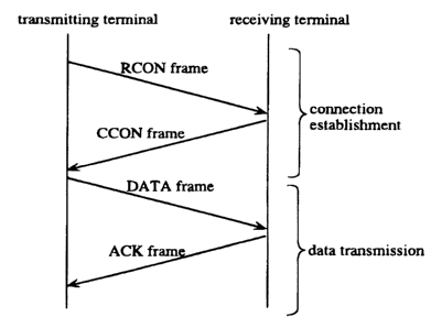
FIG. 2 shows a frame transmission between two terminals.
Here, a "frame" represent a minimum unit of information to be
transmitted to/from the radio communication apparatus. The
frames are classified into four types: an RCON (Request
Connection) frame and a CCON (Confirm Connection) frame which
are used for establishing a connection, and a DATA frame and
an ACK (Acknowledgement) frame which are u:;ed for transmitting
14
~m~.ss~
data.
As shown in FIG. 2, a transmitting terminal transmits an
RCON frame, and a receiving terminal returns a CCON frame,
thereby establishing a connection. In response to the
establishment of the connection, the transmitting terminal
transmits a DATA frame, and the receiving terminal returns an
ACK frame, thereby completing the transmission of data for one
frame. The transmission of the DATA frame and the ACK frame
are repeated until all the necessary data are transmitted.
FIGS. 3A-3F show the formats of these frames. FIG. 3A
shows components that all the frames commonly have, namely,
preamble, start delimiter, common header, CRC (Cyclic
Redundancy Check) code, and end delimiter. The DATA frame
further has a data unit. The CRC code indicates information
necessary for detecting bit errors.
FIG. 3B show the format of a common header, which consists
of a type field, a destination address field, a source address
field, and a sequence number field.
The type field carries the type of its frame. The most
significant bit of the type field is called EOP ( End of Packet )
bit. In the case of RCON and CCON frames, the EOP bit always
has a 0 value. In the case of DATA frames, the EOP bit is set
to 1 value only when the frame is the last frame constructing
a data packet sent from an upper layer protocol, and otherwise
it is set to a 0 value. The EOP bit of an ACK frame is
supposed to be equal to the EOP bit of the DATA frame which has
214.4666
been dust confirmed.
The destination field carries a destination address.
The source address field,carries the address of the radio
communication apparatus, which tries to send the frame.
The sequence number field in an RCON frame carries the
sequence number of the first DATA frame t~o be transmitted on
a connection established by the use of the RCON frame. The
sequence number field in a CCON frame carries the same sequence
number as in the sequence number field in the RCON frame that
is confirmed by the CCON frame. The sequence number field in
a DATA frame carries a sequence number which indicates the
order of the frame in the sequence. The sequence number field
of an ACK frame carries the sequence number of the DATA frame
that is confirmed by the ACK frame. In the case of the radio
communication apparatus of the present embodiment, the sequence
number has a 0 value when it is booted, and is incremented by
one, every time the apparatus transmits a new DATA frame, which
is not for retransmission. If a value 1 is added to the
sequence number in the case that the sequence number is the
maximum value to be obtained with the bit length of the
sequence number field, the value becomes U.
FIG. 3C shows the format of an RCON f~°ame. An RCON frame
does not have a data unit, its type field carries a value which
is identified as an RCON frame, and its EOP bit always has a
0 value. The sequence number field carries the sequence number
of the next coming DATA frame.
16
214.4666
FIG. 3D shows the format of a CCON frame. A CCON frame
does not have a data unit, its type field carries a value which
is identified as a CCON frame, and its EOP bit always has a 0
value. The sequence number field carries the sequence number
written in the RCON frame to be confirmed by the CCON frame.
FIG. 3E shows the format of a DATA frame. A DATA frame
has a data unit, and its type field carries a value which is
identified as a DATA frame. The EOP bit is set to 1 in the
case that the DATA frame is the last frame constructing a data
packet sent from an upper layer protocol, and otherwise it is
set to 0. The sequence number field carries the sequence
numbers of the DATA frame, which represents the order of the
DATA frame.
FIG. 3F shows the format of an ACK frame. An ACK frame
does not have a data unit, and its type field carries a value
which is identified as an ACK frame. Its EOP bit is supposed
to be equal to the EOP bit of the DATA frame to be confirmed
by the ACK frame. The sequence number fiE~ld carries the same
sequence number written in the DATA frame: to be confirmed by
the ACK frame.
( The overall construction of the radio communication apparatus )
FIG. 4 shows the construction of the radio communication
apparatus of the present embodiment, composed of a CPU 0, a
memory 1, a DMA controller 2, an MAC unit: 3, a modem 4 for a
data channel, a modem 5 for a busy tone channel, a bus 6, a
17
2144fi~6
duplexer 7, and an antenna 8.
The CPU 0 is in charge of data communication with the
memory 1, frame generation, connection management, MAC unit 3
operation management, communication with users, and the entire
apparatus management.
The memory 1 stores data to be transmitted and received
data, frames generated or received by the CPU 0, and connection
control tables generated by the CPU 0.
The DMA controller 2 performs data conununications between
the MAC unit 3 and the memory 1.
The MAC unit 3 is in charge of data format conversion
between the memory 1 and the modems 4 and 5, frame border
recognition, attachment and detachment of preambles, start
delimiters, and end delimiters, generation and examination of
CRC codes, and identification of received frame addresses.
The modem ~ far the data channel modulates a carrier wave
having a frequency for the data channel with data sent from the
MAC unit 3, thereby transmitting the modulated signal to the
duplexer 7, and also detects data from a signal sent from the
duplexer 7 to transmit them to the MAC unit 3.
The modem 5 for the busy tone channel modulates a carrier
wave having a frequency for the busy tone channel with data
sent from the MAC unit 3, thereby transmitting the modulated
signal to the duplexer 7, and also detects data from a signal
sent from the duplexer 7 to transmit them to the MAC unit 3.
In the present embodiment, the radio waves having different
18
214466
frequency bands from each other are respectively assigned to
the data channel and the busy tone channel.
The bus 6 is a.medium for. the exchange of control signals
among the components of the radio communication apparatus, and
for the data transmission between the memory 1 and the DMA
controller 2.
The duplexer 7 distributes signals sent from the antenna
8 to the modem 4 for the data channel and to the modem 5 for
the busy tone channel, depending on their frequency bands. The
duplexer 7 also combines the signals sent from both modems 4
and 5, thereby forwarding them to the antenna 8.
The antenna 8 transmits and receives :radio signals.
(The construction of MAC unit 3)
FIG. 5 shows the detailed construction of the MAC unit 3
which is composed of a MAC control unit 30, a FIFO 31 for
reception, a FIFO 32 for transmission, a busy tone reception
unit 33, a busy tone transmission unit 34, a data reception
unit 35, a data transmission unit 36, and a busy tone
determination unit 37.
The MAC control unit 30 controls each component of the MAC
unit 3 and exchanges information with the CPU 0 via the bus 6,
and further informs the modems 4 and 5 the timing for switching
between the reception and transmission of frames via the signal
;Z5 conductors 302 and 303.
The FIFO 31 for reception and FIFO 32 for transmission are
19
21 ~.~.G 6 G
buffers for transmitting data to and receiving data from the
DMA controller 2 respectively.
The busy tone reception unit 33 detects a frame head by
detecting a start delimiter from a bit stream received through
the modem 5 for the busy tone channel, and checks the
destination address to determine whether the frame is destined
for the apparatus. If it is destined for the apparatus, the
busy tone reception unit 33 reports this to the MAC control
unit 30, and transfers the received frame to the FIFO 31 for
AO reception. The received frame is further transferred to the
memory 1 by the DMA controller 2.
The busy tone transmission unit 34 transmits a frame sent
from the FIFO 32 far transmission under the direction of the
MAC control unit 30 through the modem 5 for the busy tone
channel.
The data reception unit 35 detects a frame head by
detecting a start delimiter from a bit stream received through
the modem 4 for the data channel, and checks the destination
address to determine whether the frame is destined for the
apparatus. If it is destined for the apparatus, the data
reception unit 35 reports it to the MAC control unit 30,
and deletes the preamble, start delimiter, CRC code, and end
delimiter from the received frame. Then, the data reception
unit 35 transfers the rest of the received frame to the FIFO
31 for reception. The contents of the FIFO 31 is transferred
to the memory 1 by the DMA controller 2.
21.4.666
The data transmission unit 36 generatE~s a frame by adding
the preamble, start delimiter, CRC code, and end delimiter to
the contents of the FIFO 32 under the direction of the MAC
control unit 30, and transmits the frame to the modem 4,
thereby transmitting the frame on the data channel.
The data transmission from the memory 1 to the FIFO 32 is
performed by the MAC controller 2.
The busy tone determination unit 37 observes the strength
of a signal on the busy tone channel received by the modem 5
and determines whether the signal strength is beyond a
predetermined one. The observed result is reported to the MAC
control unit 30 via the signal conductor 304. The MAC control
unit 30, prior to the transmission of an RCON frame or a CCON
frame, performs a gap detection with a signal sent through the
:L5 signal conductor 304, to detect whether the busy tone channel
is free from a signal having more strength than determined for
over a predetermined time period (gap time).
(The construction of modems 4 and 5)
FIG. 6A shows the construction of the rnodem 4 for the data
:?0 channel.
The Rx/Tx switch 40 switches between the transmission mode
and the reception mode under the direction of the MAC control
unit 30.
Under the reception mode, signals frorn the duplexer 7 are
:?5 sent to the demodulator 44 through the receiver 43, and further
21
2.44666
sent to the data reception unit 35 after detection, decision,
and clock recovery have been applied.
Under the transmission mode, the modulator 42 modulates
a carrier wave for the data channel by means of a bit stream
sent from the data transmission unit 36, thereby generating
modulated signals. The modulated signals are sent to the
duplexer 7 through the transmitter 41.
The Rx/Tx switch 40, the transmitter 41, and the receiver
43, which are connected with the MAC control unit 30 through
a signal conductor 302, operate under the direction of the MAC
control unit 30.
FIG. 6B shows the construction of the modem 5 for the busy
tone channel, which is similar to the construction of the modem
4 shown in FIG. 6A. The receiver 53 and the busy tone
determination unit 37 are connected to each other via a signal
conductor 301, which informs the strength of a signal received
on the busy tone channel. The busy tone determination unit
37 determines whether there is a signal having more strength
than predetermined by means of the signal conductor 301, then
reports the result to the MAC control unit 30.
(Overall operations of the radio communication apparatus)
FIG. 7 is a flowchart showing overall operations of the
radio communication apparatus of the present embodiment. More
detailed operations will be described later with reference to
FIGS. 8 and 9.
22
2144fifi6
Having received an RCON frame destined for itself on the
busy tone channel (step R), the radio communication apparatus
performs a data reception subroutine, and :returns to the step
R when the data reception has been completed.
Not having received an RCON destined for itself (step R),
the radio communication apparatus determines whether there are
data to be transmitted in the memory 1 (step S). When the
presence of such data has been determined, the apparatus
performs a_data transmission subroutine, and returns to the
step R. In contrast, when the absence of such data has been
determined, the apparatus directly returns to the step R.
As will be described below, when an RCON frame destined
for the apparatus has been received on thE: busy tone channel
at an early stage of a connection establishing process, a data
reception process has precedence over the data transmission
process.
(Data transmission operations)
Detailed operations for data transmission of the radio
communication apparatus are as follows.
FIG. 8 is a flowchart showing data transmission operations
of the apparatus. When data to be transmitted have been stored
to the memory 1 by means of an upper layer application (step
S), the CPU 0 generates a connection control table and stores
:?5 it to a predetermined area in the memory 1 ( step SO1 ) . The
connection control table includes the dest_Cnation address for
23
2144GE~
the data, the current value of the sequence number ( hereinafter
CSEQ), the maximum frame length inherent to the data channel
to be used, the number of times to retran:~mit an RCON frame,
the number of times to retransmit a DATA frame, and a
connection state.
In step SOl, the address of the receiving station is set
to the destination address of the data to be transmitted, and
CSEQ is set to a value to be obtained by adding 1 to the
sequence number of the latest-transmitted DATA frame
:LO (hereinafter LSEQ). The numbers of times to retransmit an RCON
frame and a DATA frame are both set to 0. The connection state
is set to an RCON transmission wait state.
In data transmission, the CPU 0 stores CSEQ to a
predetermined area in the memory 1 as LSEQ, every time a new
.l5 DATA frame is transmitted, which is not for retransmission.
Then, the CPU 0 generates a common :header of the RCON
frame (hereinafter RCON header), and stores it to a
predetermined area in the memory 1 ( step S02 ) . The parts other
than the common header, namely, preamble, start delimiter, CRC
:?0 code, end delimiter are generated in the busy tone transmission
unit 34 and added to the RCON frame when it is transmitted.
The type field in the RCON header carries an
identification of the type of RCON. The destination address
field and the sequence number field respectively carry the
~'.5 destination address and CSEQ of the connection control table.
The source address field carries the address of the apparatus.
24
~1ø~.ss6
The CPU 0 stores the generated RCON header to the FIFO 32
for transmission (step S03). To be more specific, the CPU 0
informs the DMA controller 2.of the leading address and the
length of the RCON header in the memory 1. The DMA controller
2 serially stores data for the informed length starting from
the informed address to the FIFO 32. The CPU 0 informs the MAC
control unit 30 of the start of the data transmission as well
as directing it to store the RCON header. The generated RCON
header is held in the memory 1 until it :is confirmed by the
CCON frame.
The MAC control unit 30 starts to observe the conditions
of the busy tone channel in accordance with the signal to be
sent from the busy tone determination unit 37 to the signal
conductor 304 (step S04). When the signal on the signal
conductor 301 has less strength than the prE~determined one, the
busy tone determination unit 37 determines the absence of an
effective signal on the busy tone channel, and transmits a low
level signal through the signal conductor 304 to inform the MAC
control unit 30 of the determination. In accordance with this,
the MAC control unit 30 regards the absence of the effective
signal for the predetermined gap time as the detection of a gap
on the busy tone channel.
In response to the detection of the gap (step S05), the
MAC control unit 30 switches the Rx/Tx switch 50 in the modem
5 to the transmitter, by sending a signal to the signal
conductor 303, thereby setting the modem 5 to the transmitting
214.4666
mode. This signal is also used to initiate the transmitter 51.
The MAC control unit 30 directs the busy tone transmission unit
34 and the FIFO 32 to trar~smit a frame. The busy tone
transmission unit 34,generates a data atream including a
preamble and a start delimiter at the head of an RCON header,
and converts the data stream into a bit stream for the
transmission path, and starts to transmit it to the modulator
52 of the modem 5. When the RCON header in the FIFO 32 has
been all transmitted, the busy tone transmission unit 34 adds
already calculated CRC code and the end delimiter to the end
of the RCON header, converts it into a bit stream for the
transmission path, and transmits it to the modulator 52. The
modulator 52 modulates a carrier wave for the transmitted bit
stream, and transmits the bit stream onto the busy tone channel
through the transmitter 51, duplexer 7, and antenna 8 (step
S06).
When the transmission of the end delimiter of the RCON
frame to the modulator 52 has been compleaed, the busy tone
transmission unit 34 informs the MAC control unit 30 of the
completion of the transmission. The MAC control unit 30 waits
until the modem 5 completes the transmission of the RCON frame,
then switches the Rx/Tx switch 50 to the receiver, by sending
a signal to the signal conductor 303. As a result, the modem
5 for the busy tone channel is set to t;he reception mode.
This signal is also used to initiate the receiver 53. Then,
the MAC control unit 30 informs the CPU 0 of the completion of
26
.~ ~l,~~ssb
the RCON frame transmission. The CPU 0 changes the connection
state of the connection control table in the memory 1 to the
CCON reception wait state (Step S07). Then, the CPU 0 starts
the CCON wait timer with 0 as the initial value (step S08).
When a signal on the busy tone channel is received by the
receiver 53 in the modem 5 and sent to the busy tone reception
unit 33 through the demodulator 54 in the form of a bit stream,
the busy tone reception unit 33 finds out the bit pattern of
the start delimiter from the bit stream, and regards the bits
following the start delimiter as a frame. Judging the frame
to be destined for the apparatus, the busy tone reception unit
33 reports it to the MAC control unit 30, and converts the
received frame from the bit stream for the transmission path
into a data stream until the end delimiter i,s detected, storing
them to the FIFO 31 for reception. The end delimiter is not
stored to the FIFO 31. The busy tone reception unit 33
examines the CRC of the frame. Prior to t;he frame storage to
the FIFO 31, the MAC control unit 30 sends a control signal to
the FIFO 31 to enable the writing of data from the busy tone
reception unit 33.
The DMA controller 2 transfers frames stored in the FIFO
31 to the memory 1. To be more specific, the DMA controller
2, which holds the leading address and length of the preserved
area on the memory l, starts to transfer the contents of the
2 5 FIFO 31 from the site of the leading addrea s, and interrupts
in the CPU 0 when all the contents of the FIFO 31 have been
27
214.466
stored or when the stored data has reached the length. In this
embodiment, the preserved area in the memory 1 is supposed to
be large enough to store at least one frame including a DATA
frame. Under such assumption, the DMA controller starts an
interruption when all the contents of th.e FIFO 31 have been
stored in the memory 1.
Having detected a CRC error in the process of CRC
examination, the busy tone reception unit 33 reports it to the
MAC control unit 30. The MAC control. unit 30 makes an
interruption to inform the CPU 0 of the C:RC error. The CPU 0
directs the DMA controller 2 to transmit next data to the very
area in the memory 1 where the frame with the CRC error is
stored, thereby eliminating the frame.
Receiving the interruption which informs the completion
of the frame storage, and not receiving the interruption which
informs the detection of the CRC error, t:he CPU 0 checks the
type field of the frame stored in the memory 1. When the type
is CCON (step S09), the contents of the :>ource address field
and the sequence number field are compared with the contents
of the connection control table. When they agree (step S10),
the CPUO stops the CCON wait timer (step S11), and deletes the
RCON header held in the memory 1 for retransmission.
Then, the CPU 0 directs the MAC control unit 30 to start
busy tone transmission. The MAC control unit 30 sends a signal
to the signal conductor 303 to switch the: Rx/Tx switch 50 in
the modem 5 to the transmitter, thereby setting the modem 5 to
28
~1~.~.~~(i
the transmission mode. The signal is also used to initiate the
transmitter 51. The MAC control unit 30 directs the busy tone
transmission unit 34 to start to transmit a bit stream
including a predetermined iterative bit pattern for busy tones
to the modulator 52 in the modem 5. The modulator 52 modulates
the received bit stream in accordance with the frequency band
and the modulation scheme for the busy tone channel, and starts
to transmit it on the busy tone channel through the transmitter
51 (step S12).
1.0 Directing the MAC control unit 30 to start a busy tone
transmission, the CPU~O updates the connection information on
the connection control table with the contents indicating the
connection establishment state (step S13). Thus, the
connection has been established.
Then, the CPU 0 generates a DATA frame smaller than the
maximum size held in the connection control table from data on
the memory 1, and sends the DATA frame on the data channel
(step S14).
To be more specific, the CPU 0 generates a common header
of a DATA frame (hereinafter DATA header) from the connection
control table. The type field in the DATA header has an
identification of the type of DATA. The destination address
field has the address of the receiving station in the
connection control table. The source address field has the
address of the apparatus. The sequence number field has the
CSEG of the connection control table. Then, the CPU 0 takes
29
~14.4fi6~
out data held in the memory 1, deducting the total length for
the preamble, start delimiter, common header, CRC code, and end
delimiter from the maximum .frame length on the connection
control table, and links the taken data to the end of the DATA
header as a data part. When the data part includes the end bit
of the data held on the memory 1, the EOP bit of the type field
is set to 1, and otherwise it is set to 0. The DATA header
linked with a data part is called a partial DATA frame
hereinafter. The partial DATA frame, which is obtained by
deducting the preamble, start delimiter, CRC, and end delimiter
from the DATA frame, 'is a main part of a DATA frame. The CPU
0 stores a partial DATA frame thus generated to a predetermined
area in the memory 1. The partial DATA frame is kept for
retransmission even after it has been transmitted on the data
channel until an ACK frame to confirm the DATA frame is
received.
Then, the CPU 0 directs the MAC control unit 30 to
transmit a DATA frame, and further directs the DMA controller
2 to start the transmission of the partial DATA frame on the
memory 1 to the FIFO 32. The transmission is performed in the
same manner as the transmission of the RCON header explained
in step 503.
The MAC control unit 30 sends a signal to the signal
conductor 302 to switch the Rx/Tx switch 4~0 in the modem 4 to
the transmitter, setting the modem 4 to the transmission mode. r
The signal is also used to initiate the transmitter 41. The
~a.~~.sss
MAC control unit 30 directs the data transmission unit 36 and
the FIFO 32 to start a frame transmission. Then, the data
transmission unit .36 converts a data stream composed of a
partial DATA frame, a preamble, and start delimiter into a bit
stream for the transmission path, starting to transmit it to
the modulator 42 in the modem 4. The data transmission unit
36 calculates a CRC code during the transmission of the bit
stream. After the transmission of the partial DATA frame, the
data transmission unit 36 adds the calculated CRC code and end
delimiter to the end of the partial DATA frame, and sends it
to the modulator 42 in the form of a bit stream for the
transmission path. The modulator 42 modulates a carrier wave
for the transmitted bit stream in accordance with the frequency
band and modulation method for the data channel, and transmits
its bit stream on the data channel via the transmitter 41, the
duplexer 7, and the antenna 8.
Completing the transmission of the end delimiter, the
data transmission unit 36 reports this to the MAC control unit
30. The MAC control unit 30 waits until the modem 4 completes
the transmission of the DATA frame, then switches the Rx/Tx
switch 40 to the receiver by sending a signal to the signal
conductor 302, setting the modem 4 to the reception mode. .The
signal is also used to initiate the receiver 43. Then, the MAC
control unit 30 informs the CPU 0 of the completion of the DATA
frame transmission.
Informed of the completion of the DATA frame transmission,
31
.. 2~~46ss
the CPU 0 starts the ACK wait timer, with 0 as the initial
value (step S15).
When a signal on the data channel has been sent to the
receiver 43 in the modem 4 and further to the data reception
unit 35 in the form of a bit stream through the demodulator 44,
the data reception unit 35 finds out the bit pattern of the
start delimiter from the bit stream, and regards the bits
following the start delimiter as a frame. Recognizing that the
frame is destined for the apparatus, the data reception unit
35 reports it to the MAC control unit 30, and starts to store
the received frame to the FIFO 31 for reception. Prior to the
frame storage to the FIFO 31, the MAC control unit 30 sends a
control signal to the FIFO 31 to enable the writing of data
from the data reception unit 35. The data reception unit 35
examines the CRC in the same manner as the reception a CCON
frame in step S09. When a CRC error has been detected, it is
processed in the same manner as explained in the reception of
a CCON frame.
In response to the start of storing a data stream to the
FIFO 31 for reception, the DMA controller 2 starts to transfer
a frame stored in the FIFO 31 to the memory 1 in the same
manner as explained in the CCON frame transmission in step 509.
If the DMA controller 2 makes an interruption to the GPU 0 to
report the completion of the frame storage, and there is no CRC
error, then the CPU 0 checks the type field of the frame to
determine whether the frame is an ACK frame ( step S16 ) . If it
32
~1~.4sss
is an ACK frame, then the contents of the :>ource address field
and the sequence number field are compared with the address of
the destination station and .CSEQ in the connection control
table (step S17). When they agree, the CPU 0 stops the ACK
wait timer (step S18), and increments the 'value of CSEQ on the
connection control table by one (step S19). Furthermore, the
CPU 0 releases the area in the memory 1 where DATA frames which
are held for retransmission is stored (step S20).
The CPU 0 checks the EOP bit of the received ACK frame
(step S21), and when the bit has a 0 value, the operation goes
back to step S14 to transmit the rest of the data.
. When the bit 'has a 1 value, the CPU 0 considers that all
the data to be transmitted in the memory 1 have been
successfully received by the destination station, and directs
the MAC control unit 30 to terminate the busy tone
transmission. The MAC control unit 30 directs the busy tone
transmission unit 34 to stop the busy tone transmission (step
S22). Then the MAC control unit 30 sends a signal to the
signal conductor 303 to switch the Rx/Tx switch 50 in the modem
5 to the receiver, thereby setting the modem 5 to the reception
mode. This signal is also used to initiate the receiver 53.
The MAC control unit 30 reports the completion of the busy tone
transmission to the CPU 0. After the completion of the busy
tone transmission, the CPU 0 clears the contents of the
connection control table (step S23), and returns to the start.
Recognizing the reception of an RCON frame destined for
33
214466
the apparatus on the busy tone channel (step S051) in the same
manner as explained in the reception of the CCON frame in step
S09 before a gap is detected i.n step 505, the CPU 0 clears the
connection control table (step 5052) and proceeds to step RO1
to carry out a data reception process which will be described
below. Until an RCON frame is received, the CPU 0 continues
to observe the busy tone channel back in the step 504.
If the value of the CCON wait timer has reached the
maximum wa~.t time for the connection establishment confirmation
without the reception of a CCON frame on the busy tone channel
in the step S09 (step 5091), the CPU 0 updates the number of
times of RCON frame retransmission on the connection control
table by adding one (step 5092). Then, the CPU 0 checks
whether the number of times of the RCON frame retransmission
has reached the predetermined maximum number of times for the
connection establishment request (step 5093). If it has
reached the number, the operation goes to step S23 to clear the
connection control table, and returns to the start of the
operation. If it has not reached the number, the CPU 0 put the
connection information on the connection control table back to
the RCON frame transmission wait state ( ste:p 5094 ) , and returns
to the step S03 to retransmit an RCON frame including an RCON
header held in the memory 1 for retransmission.
(Data reception operations)
Operations for data reception of the radio communication
34
214.4~~fi
apparatus of the present embodiment is described as follows
with reference to the FIG. 9.
Recognizing the receptipn of an RCOIU frame on the busy
tone channel (step R),in the same manner .as explained in the
reception of the CCON frame in step 509, the CPU 0 generates
a connection control table and stores it in a predetermined
area in the memory 1 (step RO1). In the step RO1, the address
of the destination station and CSEQ on the connection control
table are respectively set to the contents of the destination
address field and the sequence number field of the received
RCON frame. The numbers of times of RCON frame retransmission
and DATA frame retransmission are set to any values, and the
connection state is set to the CCON transmission wait state.
Then, the CPU 0 generates a common header of a CCON frame
( hereinafter CCON header ) and stores it in a predetermined area
in the memory 1 (step R02).
The type field in the CCON header has an identification
of the type of CCO~t frame. The destination address field and
the sequence number field respectively have the address of the
destination station and CSEQ on the connection control table.
The source address field has the address of the apparatus. The
CPU 0 transfers the generated CCON header to the FIFO 32 in the
same manner as explained in the step S03 (step R03), and at the
same time, directs the MAC control unit 30 to start a CCON
frame transmission. Furthermore, the CPU 0 initiates the gap
wait timer with an initial value 0 (step R04).
2144-66fi
The MAC control unit 30 starts to observe the busy tone
channel in the same manner as in the steps S04 and S05 (step
R05), to determine whether a_gap has been detected from the
busy tone channel (step R06).
In the case where a gap has been detected, a CCON frame
is generated from the CCON header in the FIFO 32, and
transmitted on the busy tone channel (step R07).
Completing the transmission of the end delimiter of the
CCON frame, the busy tone transmission unit 34 reports it to
the MAC control unit 30. The MAC control unit 30 waits until
the modem 5 completes the transmission of the CCON frame, then
switches the Rx/Tx switch 50 to the receiver by sending a
signal to the signal conductor 303, setting the modem 5 to the
reception mode. The signal is also used to initiate the
receiver 53. Then, the MAC control unit 30 informs the CPU 0
of the completion of the CCON frame tran:;mission. Receiving
the information, the CPU 0 stops the gap wait timer ( step R08 ) .
The CPU 0 waits for an estimated propagation delay of the
CCON frame to be caused between the apparatus and the
destination terminal (step R09), and directs the MAC control
unit 30 to start the busy tone transmission, which is started
in the same manner. as in the step S12 (step R10). Then, the
CPU 0 changes the connection state on the connection control
table to the connection establishment state (step R11), to
initiate the connection holding timer with an initial value 0
(step R12).
36
214456
When a frame on the data channel destined for the
apparatus has been stored in the memory 1 in the same manner
as an ACK frame :is received in the step S16, the CPU 0
determines whether it,is a DATA frame or not by checking the
type field (step R13). If it is a DATA frame, then the CPU 0
compares the contents of the source address field with the
address of the destination terminal on the: connection control
table (step R14). If they agree, the CPU 0 further compares
the contents of the sequence number field (hereinafter RSEQ)
with the CSEQ on the connection control table. If the RSEQ and
the CSEQ agree (step R15), then the data part in the received
DATA frame is taken out and stored in the predetermined area
(step R16). The CPU 0 further increments the CSEQ on the
connection control table by one (step R17).
Then, an ACK frame, which confirms the reception of the
DATA frame is generated and transmitted in the same manner as
the generation and the transmission of a DATA frame in the step
S14 (step R18). The address of the destination terminal and
RSEQ on the connection control table are .respectively written
into the destination address field and the sequence number
field of the ACK frame being transmitted. The EOP bit of the
received DATA frame is written on the EOP bit of the ACK frame.
The completion of the ACK frame transmission is reported to the
CPU 0 through the data transmission unit 36 and the MAC control
unit 30 in the same manner as in the step S14.
In response to the report, the CPU 0 initiates the
37
~m~sss
connection holding timer again with an initial value 0 (step
R19).
The CPU 0 checks the EOP bit of the received DATA frame
(step R20), and in the case that the value is 0, goes back to
the step R13 to wait for the reception of a DATA frame from the
destination station. In the case that the E0P bit has a 1
value, the CPU 0 waits until the connection hold timer reaches
a predetermined maximum connection hold time (step R21), and
terminates- the busy tone transmission in the same manner as
explained in the step S22 (step R22). Being informed of the
completion of the busy tone transmission through the busy tone
transmission unit 34 and the MAC control unit 30, the CPU 0
clears the connection control table (step R23) and returns to
the start. If the gap wait timer has reached its maximum
without the detection of a gap in the step R09 ( step 8061 ) , the
operation proceeds to the step R23 to release the connection
control table and returns to the start.
If the connection holding timer has reached the
predetermined maximum connection hold time without the
reception of a DATA frame in the step R13 (step 8131), the CPU
0 proceeds to step R22 to terminate the busy tone transmission,
regarding the connection as being disconnected. 'Phen, the CPU
clears the connection control table and goes back to the start.
When the RSEQ and the CSEQ do not agree in the step R15,
the received DATA frame is abandoned (step R151). When the
RSEQ is smaller than the CSEQ (step 8152), it is regarded as
38
2m~.sss
double reception, and the operation proceeds to step R18,
skipping to take out a data part or to update the CSEQ. In
the step R18, an. ACK frame. to confirm the DATA frame is
generated and transmitted to perform the subsequent process.
When the RSEQ is larger than the CSEQ, it is regarded as
an abnormal frame, and the operation directly goes back to step
R13.
Before the connection is released in the step R21, if a
DATA frame is received from the destination terminal while the
ZO CPU 0 is waiting the connection hold timer to reach its maximum
(step 8211), the CPU~O generates and transmits the ACK frame
to confirm the DATA frame ( step 8212 ) , initiates the connection
hold timer again (step 8213), and goes back to step R21.
(Effects)
As apparent from the explanation here;inbefore, according
to the radio communication apparatus of the present embodiment,
both the transmitting terminal and the receiving terminal are
transmitting a busy tone on the busy tone channel when they are
n data communication. Another terminal Which is ready to start
transmission must confirm that there is no busy tone on the
busy tone channel. Consequently, all the terminals in the
communication range of these transmitting and receiving
terminals know that these two are in communication, so that
they do not disturb it. The HTP is avoided in such a manner
according to the radio communication apparatus of the present
39
~144sss
embodiment.
Furthermore, two terminals within a certain communication
range can establish a connection and exchange data without a
third terminal such as a base station, so that a distributed
environment can be realized.
Furthermore, the entire network is prevented from becoming
unable to communicate due to a failure of i:he base station.
Once a connection has been established between a
transmitting terminal and a receiving terminal, all the data
frames constituting a data packet are repeatedly transmitted.
While the data frames are being repeatedly transmitted, busy
tones are transmitted continuously, so that the data
communication between the two terminals is not disturbed by
other terminals. Consequently, the radio communication
apparatus of the present embodiment has data transmission with
higher efficiency than other systems that daemand a connection
establishment for each data frame.
FIG. 10 is a graph showing the results of a numerical
simulation of the throughput property of the radio
communication apparatus of the present embodiment together with
the results of CSMA/CA + Ack system for comparison.
According to the simulation, a 1500 byte data packet is
sent as 128 byte data frames, and the network is composed of
9 terminals: A1-A3, H1-H3, and C1-C3. The 9 terminals are
divided into 3 sub groups: A, B, and C, and communications are
carried out within each sub group. However, each terminal
2144666
sometimes receives a frame transmitted from another sub group,
causing a frame collision. The maximum confirmation wait time
is set to be 1.2 times of the. sum of a data frame propagation
delay and a confirmation frame propagation delay. The data
frames which have not been confirmed by the acknowledgement
frame is retransmitted 5 times at most. If at least one of the
data frames constituting a data packet has failed to reached
the destination station, it is considered that the transmission
of the entire data packet has been unsuccessful.
The presence and absence of HTP are expressed by using two
types of average path loss, assuming that the path loss between
two terminals obeys a Rayleigh fading. The: average path loss
in the case that HTP is present is shown in FIG. 11, and the
average path loss in the case that HTP is absent is fixed to
1.5 87dB. When the path loss is over 115dB, a frame is assumed to
be dropped.
In FIG. 10, the horizontal axis indicates the total load
of all the terminals normalized at a transmission rate unique
to the data channel. The total load is one of the parameters
for the simulation, and indicates a degree of the data
transmission congestion in the entire network. The vertical
axis indicates the total throughput (normalized throughput) of
all the terminals normalized with the total load. The
normalised throughput is obtained from i:he simulation and
represents the rate of successful data transmission.
As shown in FIG. 10, the radio communication method of the
41
2144~~G
present invention can produce higher throughput, and is less
affected by the HTP than the CSMA/CA + Ack scheme. As a
result, higher efficiency of data transmission can be realized.
<Embodiment 2>
The second embodiment of the present invention will be
described hereinafter in which the like components are labeled
with like reference numerals with respect to the first
embodiment,, and the description of these components is not
repeated. The busy tone channel and the data channel are
assigned different frequency bands from each other just like
in the first embodiment.
The present embodiment is different from the first
embodiment in that a data channel is used for a connection
establishment with an RCON frame and a CC01~I frame, instead of
a busy tone channel..
(The entire construction of the radio communication apparatus)
The radio communication apparatus of the present
embodiment has the same fundamental construction as the first
embodiment shown in FIG. 4; however, the MAC unit 3 and the
modem 5 for the busy tone channel are constructed differently
from their equivalents in the first embodiment. shown in FIGS.
5 and 6. The frames used in this embodiment are equal to those
used in the first embodiment shown in FIGS. 3A-3E; however RCON
frames and CCON frames to be transmitted on the busy tone
42
2144fifi6
channel in the first embodiment are transmitted on the data
channel.
(The construction of the MAC unit 3)
FIG. 12 is a block diagram showing the construction of the
MAC unit 3 of this embodiment. FIG. 12 is different from FIG.
5 showing the construction of the MAC unit 3 of the first
embodiment in that there are no busy tone reception unit 33 and
no data line extending from the FIFO 32 to the busy tone
transmission unit 34. The busy tone transmission unit 34 of
this embodiment transmits busy tones only, and the RCON frames
and the CCON frame: are transmitted by the data transmission
unit 36.
(The construction of the modem 5)
FIG. 13 is a block diagram showing the construction of the
modem 5 for the busy tone channel of the :radio communication
apparatus of this embodiment. FIG. 13 is different from FIG.
6B showing the construction of the modem 5 of the first
embodiment in that there is no demodulator 54 provided.
(Operations of the entire radio communication apparatus)
FIGS. 14-16 are flowcharts depicting aperations of the
radio communication apparatus of this embodiment, which
respectively correspond to FIGS. 7-9 of the first embodiment.
FIG. 14 shows the overall operation of the radio communication
43
2i44sss
apparatus, FIG. 15 shows the data transmission operation, and
FIG. 16 shows the data reception operation. The same
operations as the first embodiment are not explained.
In the flowchart of FIG. 14, the radio communication
apparatus performs a data reception subroutine when received
an RCON frame destined for the apparatus (step R). After the
completion of the data reception, the operation goes back to
step R.
In the case that the apparatus has not received an RCON
frame destined fox the apparatus (step R), it determines
whether there are data to be transmitted in the memory 1 (step
S). When there are such data, the apparaltus performs a data
transmission subroutine, and after the completion of data
transmission, returns to the step R. In contrast, when there
are no data to be transmitted, the apparatus directly returns
to the step R.
As will be described below, when an :RCON frame destined
for the apparatus has been received on the busy tone channel
at an early stage of the connection establishment process, a
data reception process has precedence over the data
transmission process.
(Data transmission operations)
The operations for data transmission are explained
hereafter with reference to FIG. 15. The operations up to step
S05 in FIG. 15 are included in FIG. 8 for tlhe first embodiment,
44
2144fi66
so that they are not detailed again.
Responding to the detection of the presence of a gap on
the busy tone channel at step 505, the MAC control unit 30
switches the Rx/Tx switch 40 in the modem 4 to the transmitter
by sending a signal. to the signal conductor 302, setting the
modem 4 to the transmission mode. The signal is also used to
initiate the transmitter 41. The MAC control unit 30 directs
the data transmission unit 36 and the FIFO 32 to transmit a
frame. The data transmission unit 36 generates a data stream
including a preamble and a start delimiter at the head of an
RCON header in the FIFO 32, and converts the data stream into
a bit stream for the transmission path, and starts to transmit
it to the modulator 42 of the modem 4 for the data channel.
The data transmission unit 36 calculates GRC during the
transmission of the bit stream. When the RCON header in the
FIFO 32 has been transmitted, the data transmission unit 36
adds the calculated CRC and the end delimiter to the end of the
RCON header, converts it into a bit stream for the transmission
path, and transmits it to the modulator 42. The modulator 42
modulates a carrier wave for the transmitted bit stream and
transmits the bit stream onto the data channel through the
transmitter 41, duplexer 7, and antenna 8. Thus, the
transmission of the RCON frame is started (step S06).
Having completed the transmission of t:he end delimiter of
the RCON frame to the modulator 42, the data transmission unit
36 reports it to the MAC control unit 30. The MAC control unit
2144.666
30 waits until the modem 4 completes the i:ransmission of the
RCON frame, then switches the Rx/Tx switch 40 to the receiver,
by sending a signal to the signal conductor 302. As a result,
the modem 4 for the data channel is set to the reception mode.
This signal is alsa used to initiate the receiver 43. Then,
the MAC control unit 30 informs the CPU 0 of the completion of
the RCON frame transmission. The CPU 0 changes the connection
state of the connection control table in the memory 1 to the '
CGON reception wait state (Step S07). Then, the CPU 0
initiates the CCON wait timer with 0 as the initial value ( step
S08).
When a signal on the data channel :is received by the
receiver 43 in the modem 4 and sent to the data reception unit
35 through the demodulator 44 in the form of a bit stream, the
data reception unit 35 finds out the bit pattern of the start
delimiter from the bit stream, and regards the bits following
the start delimiter as a frame. Recognising that the frame
is destined for the apparatus, the data reception unit 35
reports it to the MAC control unit 30, and converts the
received frame from the bit stream for the transmission path
into a data stream until the end delimiter is detected, storing
to the FIFO 31 for reception. The end delimiter is not stored
to the FIFO 31. The data reception unit 35 examines the CRC
of the frame. Prior to the frame storage to the FIFO 31, the
MAC control unit 30 sends a control signal to the FIFO 31 to
enable the writing of data from the data reception unit 35.
46
~~ 4.4.666
Then, it is determined whether the frame received by the
CPU 0 is a CCON frame in step S09 along with the same operation
shown in FIG. 8 for the first embodiment. The operations from
step S10 to step S2S are performed in the same manner as in the
first embodiment.
If the CPU 0 has recognized the reception of an RCON frame
destined for the apparatus ( step S051 ) before a gap is detected
in step S05 in the same manner as explained in the CCON frame
reception in step 509, the radio communication apparatus of
ZO this embodiment performs the operations on and after the step
5052, which are equal to their equivalent: in FIG. 8 for the
first embodiment.
If the value of the CCON wait timer has reached the
predetermined maximum wait time for the connection
establishment confirmation without the reception of a CCON
frame on the data channel in the step S09 (Step S091), the
radio communication apparatus of this embodiment performs the
operations on and after the step 5092, which are equal to their
equivalents in FIG» 8 for the first embodiment.
The operations from step S161 to step 5164 are also equal
to their equivalents in FIG. 8.
(Data reception operations)
The operations for data reception are explained hereafter
with reference to :FIG. 16.
Recognizing the reception of an RCON frame on the data
47
2144~b6
channel (step R) in the same manner as explained in the CCON
frame reception in step S09 in FIG. 15, the CPU 0 performs the
operations on and after the step RO1. The operations from step
RO1 to step R06 are equal to their equivalents in FIG. 9 for
the first embodiment.
In the case where a gap has been detected on the busy tone
channel in step ROfi, a CCON frame is generated from the CCON
header in the FIFO 32 for transmission, and transmitted on the
data channel (step R07).
Completing the transmission of the end delimiter of the
CCON frame, the data transmission unit 36 reports it to the MAC
control unit 30. The MAC control unit 30 waits until the modem
4 completes the transmission of the CCON frame, then switches
the Rx/Tx switch 40 to the receiver by sending a signal to the
signal conductor 302, setting the modem 4 to the reception
mode. The signal is also used to initiate the receiver 43.
Then, the MAC corxtrol unit 30 informs the CPU 0 of the
completion of the CCON frame transmission. Receiving the
information, the CPU 0 stops the gap wait timer (step R08).
Then, the operations from step RO!3 to step R23 are
performed in the same manner as explained in FIG. 9 for the
first embodiment.
The operations in the cases where the gap wait timer has
reached its maximum without the detection of a gap on the busy
tone channel in the step 8061, where the connection hold timer
has reached its maximum time without the reception of a DATA
48
~i4~.sss
frame in the step 8131, and where RSEQ and CSEQ do not agree
to each other in the steps 8151 and 8152 are equal to the
respective operations in the first embodiment.
Furthermore, the operations from the step 8211 to step
8213 are equal to their equivalents in the first embodiment.
(Effects)
As apparent from the explanation hereinbefore, the radio
communication apparatus of this embodiment produces the same
effects as those of the first embodiment. 7:n other words, HTP
can be solved because both the transmitting terminal and the
receiving terminal transmit a busy tone on the busy tone
channel when they are in data communication.
Furthermore, two terminals within a certain communication
range can establish a connection and exchange data without a
third terminal such as a base station, so that a distributed
environment can be realized.
Furthermore, the entire network is prevented from becoming
unable to communicate due to a failure of the base station.
Since the controlling procedure in data transmission is
performed in the :;ame manner as in the first embodiment,
effective data transmission can be realized.
The radio communication apparatus of this embodiment has
another effect which can not be obtained from the first
embodiment. Since frames for connection establishment are
transmitted by means of the data channel, the busy tone channel
49
214466
is used exclusively to transmit busy tones. Consequently, the
band width of the busy tone channel can be smaller than in the
first embodiment,. contributing the effective use of the
frequency band.
<EMBODIMENT 3>
The third embodiment of the present; invention will be
described hereinafter in which the like components are labeled
with like reference numerals with respect to the first and
second embodiments,, and the description of these components is
not repeated. The busy tone channel and t:he data channel are
assigned different frequency bands from each other just like
in the first and second embodiments.
The present embodiment is different from the first
embodiment in that the data channel is used for connection
establishment, instead of the busy tone channel, and different
from the second embodiment in that busy tones are transmitted
while an RCON frame and a CCON frame are in process of
transmission.
( The overall construction of the radio communication apparatus )
The radio communication apparatus of this embodiment has
the same fundamental construction as that of the first
embodiment shown i.n FIG. 4. The MAC unit 3 of the present
embodiment has the same construction as that of the second
embodiment shown in FIG. 12. The frames of this embodiment are
2~~.~.~~6
the same as those of the first embadiment shown in FIG. 3;
however RCON frames and CCON frames to be transmitted on the
busy tone channel in the first embodiment are transmitted on
the data channel.
(Operations of the entire radio communication apparatus)
The operations of the entire radio communication apparatus
of the present embodiment are the same as those of the second
embodiment shown in FIG. 14 except for the contents of the data
transmission subroutine and the data reception subroutine.
(Data transmission operations)
The operations for data transmission of this embodiment
differs from those of the second embodiment only in the RCON
frame transmission operation.
FIG. 17 is a flowchart depicting the RCON frame
transmission operation of this embodiment,. which
corresponds to the step S06 of FIG. 15 which shows the RCON
frame transmission operation of the second embodiment.
In FIG. 17, having detected a gap in the busy tone channel
( step S05 in FIG. 15 ) , the MAC control unit 30 switches the
Rx/Tx switch 40 in the modem 4 and the RxfTx switch 50 in the
modem 5 to the transmitter by sending signals to the signal
conductors 302 and 303, setting the modems 4 and 5 to the
transmission mode (step S301). These signals are also used to
initiate the transmitters 41 and 51 respectively. Then, the
51
2~~.4~t;~
MAC control unit 30 directs the busy tone transmission unit 34
to start busy tone transmission.
In response to the direction of the MAC control unit 30,
the busy tone transmission unit 34 stari~s to transmit a bit
stream including a predetermined iterative: bit pattern for busy
tones to the modulator 52 in the modem ~5. The modulator 52
modulates a carrier wave for the transmitted bit stream in
accordance with the frequency band and modulation scheme for
the busy tone channel, and starts to transmit it on the busy
tone channel through the transmitter 51, the duplexer 7, and
the antenna 8 (step 5302).
Then, the MAC control unit 30 directs the data
transmission unit 36 and the FIFO 32 to transmit a frame. The
data transmission unit 36 generates a data stream including a
preamble and a start delimiter at the head of an RCON header
in the FIFO 32, converts the data stream into a bit stream for
the transmission path, and starts to transmit it to the
modulator 42 of the modem 4 for the busy gone channel. The
modulator 42 modulates a carrier wave for the transmitted bit
stream and transmits the bit stream on the data channel through
the transmitter 41, duplexer 7, and antenna 3 (step 5303).
The data transmission unit 36 calculates CRC during the
transmission of the bit stream to the modulator 42. After the
transmission of the RCON header stored in FIFO 32, the data
transmission unit 36 adds the calculated C:RC and end delimiter
to the end of the RCON header, and sends it to the modulator
52
2m4sss
42 in the form of a bit stream for the transmission path.
Having completing the transmission of the end delimiter
of the RCON frame .to the modulator 42 (step S304), the data
transmission unit 36 reports it to the MAC control unit 30.
The MAC control unit 30 waits until the modem 5 completes the
transmission of the RCON frame, then directs the busy tone
transmission unit 34 to stop the busy tone transmission (step
S305).
The MpC control unit 30 then switches the Rx/Tx switches
40 and 50 to the receiver by sending signals to the signal
conductors 302 and 303, setting the mod~ams 4 and 5 to the
reception mode (step 5306). These signals are also used to
initiate the receivers 43 and 53 respectively. Then, the MAC
control unit 30 informs the CPU 0 of the completion of the RCON
frame transmission. The subsequent operations are equal to the
operations on and after the step S07 in FIG. 15.
(Data reception operations)
The operations for data reception of this embodiment are
explained hereafter. The operations differs from those of the
second embodiment only in operations from a CCON frame
transmission through a busy tone transmission which correspond
to step R07 through step R10 in FIG. 16.
FIG. 18 is a flowchart depicting a CCON frame transmission
and a busy tone transmission of this embodiment, which
corresponds to the steps R07 through R1U of FIG. 16 for the
53
2m~sss
second embodiment.
In FIG. I8, having detected a gap on th.e busy tone channel
( step R06 in FIG. 16 ) , the MAC control unit 30 switches the
Rx/Tx switch 40 in the_modem 4 and the Rx/Tx switch 50 in the
modem 5 to the transmitter by sending signals to the signal
conductors 302 and 303, setting the modems 4 and 5 to the
transmission mode (step R301). These signals are also used to
initiate the transmitters 41 and 51 respectively.
Then,., the MAC Control unit 30 directs the busy tone
transmission unit 34 to start busy tone transmission. In
response to the direction of the MAC control unit 30, the busy
tone transmission unit 34 starts to transmit a bit stream
including a predetermined iterative bit pattern for busy tones
to the modulator 52 in the modem 5. The modulator 52 modulates
a carrier wave for' the transmitted bit stream in accordance
with the frequency band and modulation scheme for the busy tone
channel, and starts to transmit it on the busy tone channel
through the transmitter 51, the duplexer 7, and the antenna 8
(step 8302).
Then, the MAC control unit 30 directs the data
transmission unit 36 and the FIFO 32 to transmit a frame. The
data transmission unit 36 generates a data stream including a
preamble and a start delimiter at the head of an RCON header
in the FIFO 32, converts the data stream into a bit stream for
the transmission path, and starts to transmit it to the
modulator 42 of the modem 4 for the busy tone channel. The
54
2m~sss
modulator 42 modulates a carrier wave for the transmitted bit
stream and transmits the bit stream on the data channel through
the transmitter 41, duplexer 7, and antenna 8 (step 8303).
The data transmission unit 36 calculates CRC during the
transmission of the bit stream to the modulator 42. After the
transmission of the CCON header stoned in FIFO 32, the data
transmission unit 36 adds the calculated CRC and end delimiter
to the end of the c:CON header, and sends it to the modulator
42 in the ,form of a bit stream for the transmission path.
Having completed the transmission of the end delimiter of
the CCON frame to the modulator 42 (step 8304), the data
transmission unit 36 reports it to the MAC control unit 30.
The MAC control unit 30 waits until the transmission of the
RCON frame is completed, switches the Rx/'Tx switch 40 to the
receiver by sending a signal to the signal conductor 302,
setting the modem 4 to the reception mode (step 8305). The
signal is also used to initiate the receiver 43. Then, the MAC
control unit 30 informs the CPU 0 of the completion of the CCON
frame transmission. Being informed of the completion, the CPU
0 stops the gap wait timer (step 8306). The subsequent
operations are equal to the operations on and after the step
R11 in FIG. 16.
(Effects)
As apparent from the explanation hereinbefore, the radio
communication apparatus of this embodiment produces the same
~l~~sss
effects as those of the first and second embodiments. In other
words, HTP can be solved because both a transmitting terminal
and a receiving terminal transmit a busy tone on the busy tone
channel when they are in data communication.
Furthermore, two terminals within a certain communication
range can establish a connection and exchange data without a
third terminal such as a base station, so that a distributed
environment can be realized.
Since"the controlling procedure in data transmission is
performed in the same manner as in the first embodiment,
effective data transmission can be realized.
The busy tone channel is used exclusively to transmit busy
tones which indicate that data are in process of transmission,
so that the band width of the busy tone channel can be smaller
than in the first embodiment, contributing the effective use
of the frequency band.
The radio communication apparatus of this embodiment has
another effect which can not be obtained from the first and
second embodiments as follows.
According to the first and second embodiments, a busy tone
is not transmitted while an RCON (CCON) frame is in process of
transmission. As a result, when two terminals are in data
communication, a third terminal may start a transmission, to
disturb their data communication. This c:an be avoided if an
RCON (CCON) frame is transmitted only in a case where a gap on
the data channel has been detected in the same manner as a gap
56
214~~~6 . .
is detected on a busy tone channel, prior t:o the transmission.
However, these two different gap detectio:ns make the process
complicated and the circuit enlarged.
In contrast, according to the present embodiment, a busy
tone is transmitted prior to the transmission of an RCON ( CCON )
frame, a collision of RCON (CCON) frames can be avoided only
by checking the busy tone channel. Thus, two terminals can
establish a connection in a shorter time because they are less
affected by other terminals.
(Supplement)
( 1 ) Although the busy tone channel and the data channel are
assigned different; frequency bands from each other in the
first, second, and. third embodiments, it is possible to use
physically the same frequency band by means of time sharing or
code division.
For example, the same frequency band is :Logically used for
two channels by means of time sharing, each duplexer is
operated as an antenna switch. The duplexers at all the
terminals in a radio network switch between the busy tone
channel and the data channel at every breakpoint of time
sharing, thereby realizing two logical channels.
In the case where the same frequency band is logically
used for two channE:ls by means of code division, the modems for
the busy tone charnel and the data channeal, which correspond
to spread spectrum modulation/demodulation use a carrier having
57
~l~sss
the same frequency. The logical two channels are realized by
differentiating the spreading codes.
Thus, time sharing or code division can contribute to the
effective use of the frequency band.
(2) Although the gap times are predetermined in the first,
second, and third embodiment, they can be randomized.
(3) If a terminal which is ready to transmit an RCON frame has
received an RCON frame destined for the terminal itself while
it is observing the busy tone channel, the terminal is supposed
to clear the connection control table and to receive data in
the first, second, and third embodiments. However, the data
transmission operation can be continued, ignoring the received
RCON frame.
In addition, when a signal having more strength than
predetermined has been detected while the lousy tone channel is
being observed, before an RCON (or CCON) frame is transmitted,
the busy tone observation may be interrupted for either a
predetermined or randomized time period. This can reduce the
power consumption.
(4) A terminal which has received a DATA frame whose EOP bit
is 1 completes the transmission of a busy tans after it waits
until the maximum connection holding time is over, with the
use of the connection holding timer, thereby releasing the
connection in the first, second, and third embodiments.
However, the wait time is not necessarily limited to the
maximum connection holding time. The subsequent process may
5a
2144666
be started after a wait time which is either shorter or longer
than the maximum connection holding time, by using another
timer. After a :Longer wait,time, data retransmission in an
upper layer level which is caused by the dropping of a ACK
frame for the last DATA frame can be prevented. After a
shorter wait time,, a connection can be released faster, and as
a result, another terminal can start data transmission earlier.
(5) Although a receiving terminal returns an ACK frame every
time it receives a DATA frame in the first, second, and third
embodiments, it is not the only way. A transmitting terminal
may carry information to request acknowledgement in every
predetermined number of DATA frames, and returns an ACK frame
for the acknowledgement of all the DATA frames that have not
been acknowledged so far only in the case where the receiving
terminal has received a DATA frame including the information
to request acknowledgement. However, if it is necessary to
retransmit the DATA frame in this case, a.ll the DATA frames
which have not been acknowledged by an ACK frame must be
retransmitted. Fur another method, it is possible that no ACK
frames are transmitted at all. In this case, retransmitting
operations are up to an upper layer level.
(6) Both a tran:~mitting terminal and a receiving terminal
continue to transmit a busy tone when a connection is being
established in the first, second, and. third embodiments;
however, the busy tone may be transmitted intermittently. In
that case, it is necessary that the intermitting time period
59
~14~~G6
is below a predetermined gap time. This can reduce the power
consumption.
(7) Although a receiving terminal transmits a busy tone after
the completion of a ,CCON frame transmission in the second
embodiment, a busy tone may be transmitted at the same time as
the start of the CCON frame transmission. This makes the
second embodiment realize a function of .avoiding a collision
of CCON frames in the same manner as the third embodiment.
(8) In the third embodiment, a transmitting terminal
continuously transmits a busy tone while it is transmitting an
RCON frame; however,~the transmission of the busy tone may be
stopped when a certain time has passed after the start of the
RCON frame transmission. This can reduce the power
consumption.
Although the present invention has been fully described
by way of examples with reference to the accompanying drawings,
it is to be noted that various changes and modifications will
be apparent to those skilled in the art. Therefore, unless
such changes and modifications depart from the scope of the
present invention, they should be construed as being included
therein.