Note: Descriptions are shown in the official language in which they were submitted.
- 2l4s6sn
CLOSURE WITH STAY-OPEN LID
Field of the Invention
The present invention relates to a closure for a container. In particular, it
5 relates to a closure with a stay-open lid. The stay-open lid may be accomodated on,
for eA~,.~,lc, living-hinge closures or two-piece closures. The closure may also have
a dripless outlet. The stay-open feature is ~n~inp~l in part by the use of a nib on the
closure's lid which engages a void on the closure's base. The frictional fit between
the nib and the sides of the void keep the lid up until the user chooses to close the
10 lid on top of the base. The dripless outlet is ~ inp~i in part by using a
predetermined angle on the frusturn creating the outlet.
Backeround of the Invention
U.S. Patent No. 5,088,612 to Storar et al. describes a closure with enE~gi~g
15 finger members which tend to hold the lid in an open position. The ~ng~ing
member may tend to flex due to its length. The engagement, which takes place only
at the end, may limit the usefulness.
U.S. Patent No. 4,625,898 to Hazard describes a closure with a carn system
that allows a lid to pivot about a hinge between an open position and a closed
20 position. Similarly, U.S. Patent No. 4,220,248 to Wilson, et al., describes a closure
with cam and spring elements that hold the lid open. While these may be effective
- 214~690
to hold the lid open, the complexity of their designs increases the cost of the
closures.
U.S. Patent No. 4.635,823 to Stull provides an example of a type of spout
which is often found on closures such as these. The spout design of these closures
5 makes them susceptible to spillage and dripping. Thus, there is a need for a spout
which may dispense the contents of a container with a minimum of spillage and
dripping.
There is a need for a closure with a reliable stay-open lid that may be used
with living hinge closures or with two-piece closures. There is also a need for a
10 closure whose spout is relatively dripless.
Summarv of the Invention
The present invention is directed to a closure with a stay-open lid. The
closure may also have a dripless feature. The closure includes a base, a lid and a
15 hinge comle.;~ g the two. The hinge may be, for example, a living hinge or a two-
piece hinge. The base includes a wall, a depen-ling skirt, an outlet which may be
frustal for dispensing the contents of the container, and a void a.ljacent the living
hinge. The lid includes a lid wall, a depending skirt, a plug to close the outlet when
the lid is closed. and a nib which frictionally engages the void so as to hold the lid
20 in an open position. This nib may be. for example, in the shape of a hemisphere or
a rectangular solid. A closure according to the present invention may also include
an annular outlet separating the outlet from the base wall. A closure including such
an annular outlet may provide a better fit for the plug in certain applications.The outlet in the present invention may be frustal, in which case it extends
25 away from the base at predetermined angles. A closure including such an outlet
minimi7~s the dripping which was seen with known closures.
An annular bead may be placed around the inside circumference of the base
to allow a snap-fit ~tt~ment to a container neck.
To facilitate ease of opening, the front of the closure may have an in~Pnt~tion
30 by which the user may better grasp the edge of the skirt which depends from the lid.
In this way, the lid may be flipped up to the open position about the living hinge.
- 214~69U
Other features and advantages will hereinafter appear to those of ordinarv
skill in the art. For simplicity, the hinge shown in the figures is a living hinge, but
other types, including two-piece hinges, may also be used.
Brief Description of the Fi ures
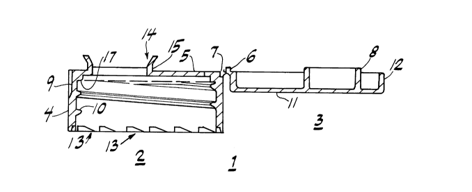
Figure 1 shows a side section of an embodiment of the present invention.
Figure 2 shows a top view of an embodiment of the present invention.
Figure 3 shows a top view of another embodiment of the present invention
which depicts a different type of living hinge.
Detailed Description
Figure I shows a side view of an embodiment of the present invention. A
closure I according to the present invention includes a base 2 and a lid 3. As shown
in Figure 2, a living hinge 16 connects the base 2 and the lid 3. A two-piece hinge
(not shown) may also be used. To present a pleasing appealance, the mostly
cylindrical exterior of the base 2 is generally flush with the mostly cylindrical
exterior of the lid 3. In this way, when the lid is in the closed position, a generally
singular cylindrical surface is evident to the COnawller.
The base 2 has a base wall 5, from which depends a first skirt 4. This skirt
4 may have threads 10 on its interior, allowing for the threaded engagement of the
closure I to the neck of a container (not shown). Alternatively, the skirt 4 may have
an annular bead located around an inner circumference, thus allowing for a snap-fit
~tt~hrr~ent to a container neck. The circumferential edge of the first skirt 4 may
further include a plurality of ratchets 13 e~ct~nrling into its interior.
T~he base wall 5 has an opening through which the colllellts of the container
may be dispensed. Circumferentially surrounding this opening may be an outwardlyangled rl ual~nl which forms a frustal outlet 14. However, it is not l~ece~c~ . y that the
outlet be frustal. If a frustal outlet is chosen, the angle at which this frustum extends
from the base wall 5 is predetermined to minimi7P dripping. For example, an angle
of approximately 30 degrees from an axis normal to the base wall 5 has been found
to significantly reduce spillage and dripping for most liquids used in these co~ahlc.a.
The outlet 14, which may be frustal, may be raised above the base wall 5 a set
2141690
~lict~nre by the interposition of an annular outlet 15 between the frustal outlet 14 and
the base wall 5. This annular outlet 15 surrounds the opening in the base wall 5, and
an inner edge of the annular outlet 15 is coupled to the edge of the opening while
an outer edge of the annular outlet 15 is coupled to an edge of the outlet 14.
S Typically, if a frustal outlet is chosen, the edge of the frustal outlet 14, with which
the edge of the annular outlet 15 is coupled, would be the circumferential edge of
the fl~ at its smallest radius.
For ease in flipping the lid 3 to its open position, an in-lçnt~tion 9 may be
provided on the exterior of the first skirt 4 in an area diametrically opposite to the
10 hinge 16, as is shown in Figure 2. This in~çnt~tion 9 generally fomns a short chord
in what may be otherwise a generally circular first skirt 4. This indentation 9 is also
present in the area of the base wall 5 which is coextensive with the indent~tion in
the first skirt. No corresponding indent~sion is present in the lid. In this way, a user
may achieve a positive grasp on the lid 3, in the area directly above the indent~tion
15 9. This allows the user to fimmly flip the lid 3 to its open position.
Altematively, a portion of the lid 3 may be m~nllf~ctllred such that it extends
beyond the first skirt 4. That is, the area of the lid wall 1 I may be larger than the
area of the cross-section of the first skirt 4.
The base 2 also includes a void 7 in a volume of the base wall 5 adjacent to
20 the first skirt 4 and the hinge 16. For example, if a living hinge is used, the living
hinge 16 may have two separate sections, and the void 7 may then be convenientlyplaced in the portion of the base wall 5 between these two portions. Altematively,
in the case of a single piece living hinge 16, the void 7 may be placed directly in
front of the hinge 16. It would also be placed in front of the hinge if the hinge were
25 in the shape of a butterfly, as shown in Figure 3. Of course, this embodiment is not
to be con~sed with the so-called butterfly hinge. In all cases, the void 7 may, for
example, be roughly hemispherical or may be in the shape of a rectangular solid.The lid 3 includes a lid wall 11 from which a second skirt 12 depends. A
nib 6 on the lid 3 frictionally engages the walls of the void 7. The nib 6 may be a
30 small mass fommed on the edge of the living hinge 16 or on the edge of the second
skirt 12. The nib 6 may also, for example, have the rough shape of a hemisphere,rectangular solid, and so on, with the primary consLIaillL being that the nib 6 must
- 214g690
fit snugly into the void 7. Clearly, the lid 3 is considered closed when the nib 6 is
snugly inside the void 7. Likewise, the lid 3 is considered open when the nib 6 is
outside the void 7. In either position, there must be enough frictional re~i~t~nre to
require the user to exert a certain amount of effort in order to flip the lid 3 to the
5 opposite position. If the nib 6 is inside the void 7, effort is le~luhed to pull it out.
If the nib 6 is outside the void 7, the nib 6 provides re~i~t~nce to movement of the
lid 3, ~, the lid 3 stays open unless it is forced closed.
The lid 3 is further provided with an annular plug 8 depending from the lid
wall 11 and extenrling in the same direction as the second skirt 12. This annular
10 plug 8 engages the outlet 14, which may be frustal, and the annular outlet if one is
provided, so as to prevent the removal of the contents of the container when the lid
is closed. The cross-sectional area of the annular plug 8 is preferably slightly less
than that of the opening in the base wall. This ensures a close frictional fit and thus
a good seal.
To further achieve a superior seal to the neck of the container, an annular lip
17 is provided. The annular lip 17 is generally positioned in the interior of the base
2, in the circumferential corner where the first skirt 4 and the base wall 5 illte~:>C~;t.
When the closure 1 is then, for example, screw-threaded on to a container neck (not
shown), the circumferential edge of the container neck contacts the annular lip 17,
20 creating a superior seal.
A closure is provided which has a stay-open feature. The closure may also
have a dripless feature. The closure may have an outlet shape which has been found
to possess superior qualities with regard to avoiding dripping and spillage. A nib on
the lid, which frictionally engages the walls of a void on the base, allows the lid to
25 stay-open unless forcibly closed by the user. The closure may also be made
irremovable.
Those skilled in the art will understand that the various optional features of
the disclosed closure may be combined in any nurnber of variations without departing
from the scope of the present invention. In addition, while the invention has been
30 described in regard to a circular closure which is screwed on to a cont~in~r~ those
skilled in the art will recognize that a closure according to the present invention may
- 214469~
be any shape and that the scope of the invention is to be limited only be the claims
appended hereto.