Note: Descriptions are shown in the official language in which they were submitted.
2144813
SOFTWARE NULLIFICATION OF TRANS~DC~K INDUCED OFFSET ERRORS
WITHIN A FLOW RATE MEASUREMENT SYSTEM
FIELD OF lNV~NlION
This invention applies to the measurement of fluid flow in a
pipe or other conduit, and most particularly applies to
measurement of airflow in railroad airbrake systems. The
invention provides apparatus and method for correcting for errors
in the measurement of the flow of air or other fluid caused by
drift of transducers used to convert fluid pressure information
into electrical signals. Most particularly, the invention provides
improved accuracy and reliability in the detection and measurement
of charging air supplied to the brake pipe of a locomotive.
BACKGROUND OF THE lNv~NlION
In the classical railroad air brake system, as developed from
the Westinghouse air brake, the brake air line which passes from
the locomotive and then from car to car down the length of the
train, provides two basic functions.
First, it is used to charge compressed air tanks in the
railroad cars. The air stored in these tanks provides the energy
needed to apply the brake shoes when a brake application is
required. When the train is running normally, and no brake
application is needed, a high pressure in the range from 70
to 110 pounds exists in the brake air line. The tanks in the cars
are charged to the same pressure as the air in the brake air line.
Second, when a brake application is required, air is
exhausted from the brake air line, causing the pressure in the
_ 2149813
brake air line to be reduced. In the cars of the train, this
reduction of pressure is used as a signal to apply the brakes. In
this event, valving in the cars utilizes the compressed air in the
tanks to apply pressure to the brake shoes so that the brakes are
applied.
After a train has been stopped by an application of the air
brakes, the air pressure in the tanks on the cars of the train is
depleted. In order for the train to operate safely, the engineer
must wait until the tanks are recharged before he puts the train
in motion.
In order for the engineer to know when the tanks are charged,
a flow meter is used to indicate the flow rate of air from a
compressor and reservoir in the locomotive to the brake pipe in
the locomotive. When this flow stops, the engineer knows that the
tanks in the cars are fully charged, and that it is safe to
proceed.
In the prior art system, an orifice is built into the line
which supplies air to the main valve which supplies air to the
brakepipe in the locomotive. Two pressure transducers are used to
measure pressures which can be used to calculate the air flow.
One tap is generally upstream of the orifice. Another tap may be
in the restricted portion of the orifice.
The difference between these signals is calculated in a
computer, which also takes the square root of the difference, and
multiplies by a constant, to obtain the flow rate.
This system has the disadvantage that if one or both of the
transducers drift, providing a reading not in accordance with its
calibration, then a false value will be computed for the airflow.
~ ~ ~ 48 ~ 3
This can be a very dangerous condition, because if a finite
airflow rate is read as being zero, the engineer may believe that
it is safe to put the train in motion when, in fact, it is not.
The system is quite sensitive to errors caused by drift of
the transducers because the step of subtracting one transducer
signal from the other causes percentage errors greater than the
errors in either transducer separately.
In order to prevent such errors, in the prior art system,
regularly-scheduled maintenance is necessary for the transducers.
A known pressure is applied to the line which the transducers
monitor, with zero airflow in the line. The transducers are then
adjusted to give exact readings of the pressure by adjusting
potentiometers on them.
This procedure has the disadvantages that it is labor
intensive, and that errors may accumulate during the entire period
between maintenance checks.
To provide additional information on railroad air brake
systems, as background for the present patent, the following
United States patents are listed for this purpose.
4,904,027 by Skantar and Sanders: DIGITAL AIR BRAKE CONTROL
SYSTEM.
5,192,118 by Balukin, Newingham and Jerina: ELECTRO-PNEUMATIC
LOCOMOTIVE BRAKE CONTROL SYSTEM.
5,222,788 by Dimsa and Jenets: MICROPROCESSOR BASED ELECTRO-
PNEUMATIC LOCOMOTIVE BRAKE CONTROL SYSTEM HAVING BRAKE ASSURANCE
CIRCUIT.
Each of these patents is assigned to the assignee of the
present invention.
~ , .,
21~813
SUMMARY OF THE lNV~;N'l'ION
The present invention provides method and apparatus for
measuring the flow rate of a fluid such as air in a fluid pressure
communication conduit which, at certain known times, carries zero
flow.
A section is provided in the fluid pressure communication
conduit which introduces local variations in the flow path. These
flow path variations cause local variations of pressure whenever
fluid flows through the conduit.
Transducers are provided to measure the local pressures, and
convert them into electrical signals. The fluid flow rate is
calculated based on the electrical signals from the transducers,
and including a correction for drift of the transducers.
When the conduit is not carrying fluid flow, a signal is
generated which indicates that condition. At that time, signals
from the transducers are used to obtain information regarding the
drift of the transducers. One or more signals indicative of the
drift of the transducers are obtained, and stored for later use
when fluid flow occurs, and a measurement of fluid flow is
required.
The invention may use a computer to calculate the fluid flow
rate based on the signals from the transducers, and signals
indicative of the drift of the transducers.
A signal indicative of the drift of the transducers is
o~tained whenever the fluid f low is reduced to zero, and a signal
indicating the condition of zero fluid flow is provided. The
signal indicative of the drift of the transistors is stored for
use when fluid flow occurs, and a correction for drift is needed.
2194813
OBJECTS OF THE lNV~NllON
The principal object of the invention is to provide an
automatic system for correcting for errors in measurement of fluid
flow in a conduit caused by drift of transducers. For the case of
a locomotive which, when it is used as a lead locomotive, supplies
compressed air to the brake line of the train, the object is to
obtain a correction for the drift of transducers used to measure
the flow rate of air supplied to the brake line. This is done
whenever the locomotive is taken out of service as a lead
locomotive. The invention provides for this to be accomplished
automatically, without the intervention of maintenance personnel.
A further object is to compare the correction which is
required with an offset error threshold value to determine whether
the correction is excessive. In the event that the correction
exceeds the offset error threshold value, an offset error signal
is generated. This may be displayed as a warning to the engineer
of the locomotive, and may also be used for control purposes.
BRIEF DESCRIPTION OF DRAWINGS
Figure 1 shows a prior art system for measuring the flow of
charging air to the brake pipe of a locomotive.
Figure 2 shows the present invention for measuring the flow
of fluid in a conduit, such as the line which supplies charging
air to the brake pipe of a locomotive, with provision for
capturing a value for drift of the transducers during times when
the fluid flow is zero.
Figure 3 shows an embodiment of the present invention in
which a differential pressure transducer is used to obtain a
difference between two pressures obtained at two points in the
conduit where variations are introduced into the flow path. Means
2144813
are provided for correcting for drift of the differential pressure
transducer during times when the fluid flow is zero.
DESCRIPTION OF THE lNV~NlION
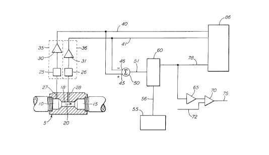
In each of the figures, element 5 is a flow block, which is a
portion of the fluid flow conduit having a variation of flowpath.
Fluid enters this element at 10 and exits at 15. The fluid flow
direction is indicated by the arrow 20. The element has a
variation of flowpath, which in these figures, is indicated as a
reduction of cross-sectional area. The region having the reduced
cross-sectional area is indicated as 18.
In each of the figures, two ports for obt~in;ng pressure are
shown. These are denoted 27 and 28. In each of the figures, 1
and 2, two pressure transducers are shown. These are indicated
generally as 35 and 36. Element 25 is a sensor which measures the
pressure at port 27, and element 26 is a sensor which measures the
pressure at port 28. Signal conditioning electronics are shown in
these transducers as elements 30 and 31. In Figure 3,
element 37 is a differential pressure transducer. This is
illustrated as having pressure sensing elements, 25 and 26, and
summing means 38, which provides a value for the difference
between the two signals. Summing means 38 also has a signal
conditioning function.
In Figure 1, the prior art, 40 and 41 denote conduction lines
which carry signals indicative of pressure from the transducers 35
and 36. Element 80 is a computer in which numerical values are
obtained for the pressures, and the pressures are subtracted to
obtain a pressure difference. The square root of the pressure
difference is then calculated and this is used as a measure of the
flow through the flow block 5 of the fluid flow conduit. In this
2144813
prior art system, correction for drift of the transducers 35 and
36 is accomplished as a maintenance step by adjusting
potentiometers associated with the signal-conditioning
electronics, elements 30 and 31.
Figure 2 shows the present invention. Elements 40 and 41 are
conduction lines which carry signals indicative of pressure from
the transducers 35 and 36. These lines enter the
computer 85 where flow is calculated. This figure also shows
means for correcting for transducer drift. Signals are conveyed
by conduction lines 40 and 41 to input terminal 45 and inverted
input terminal 46 of summing device 50 to obtain a signal on
conduction line 51 indicative of the difference between the two
transducer outputs. Element 55 is a means for generating a signal
indicting that the flow through the flow block 5 is zero.
When the present invention is applied to the charging air supply
in a railroad brake system, this signal is the charge cutout
signal. This signal is applied by conduction line 56 to
element 60.
Element 60 is a sample and hold device. When the signal on
line 56 indicates zero flow, the signal on conduction line 51 is
saved in memory, and a corresponding signal is applied to
conduction line 78. When the signal on conduction line 56
indicates that flow through flow block 5 has resumed, the sampling
function of element 60 is stopped. The signal placed on
conduction path 78 is then obtained from memory. This signal is
indicative of the drift of the transducers.
The signal on conduction path 78, along with signals from the
transducers, on conduction paths 40 and 41 are supplied to element
85. In element 85, the saved signal on conduction
2114813
path 78, which indicates the transducer drift, is subtracted from
the difference in the signals of the two transducers. This
provides a corrected value for the pressure difference between
the ports 27 and 28. The flow through the flow block 5 is then
calculated from this corrected value.
Figure 2 also shows means for generating an offset error
signal if the correction for transducer drift exceeds an offset
error threshold signal. The signal indicative of transducer drift
on conduction line 78 passes through signal conditioning means 65
to an element 70 in which it is compared with an offset error
threshold signal on conduction line 72. If the signal indicative
of transducer drift exceeds the threshold signal, then an error
signal is generated, and applied to conduction line 75.
The signal on conduction line 75 may be used to control an
indicator light or other warning device at the engineer's station
in the locomotive. This signal may also be used to control other
functions.
Figure 3 shows an embodiment of the invention in which a
differential pressure transducer is used in place of the two
transducers, 35 and 36 of the preceding figures. The differential
pressure transistor is denoted as element 37. Its function is
indicated by sensor elements 25 and 26, which supply signals to
positive and negative input terminals on the summing device 38.
Summing device 38 produces a differential pressure signal on
conduction path 51.
As in the embodiment shown in Figure 2, element 55 generates
a signal indicating the condition in which there is zero fluid
flow through the flow block 5. This signal is supplied by
conduction line 56 to element 60 which has a sample and hold
2144813
function. When the signal on conduction line 56 indicates zero
flow, the signal on conduction line 51 is saved in memory, and a
corresponding signal is applied to conduction line 78. When the
signal on conduction line 56 indicates that flow through flow
block 5 has resumed, the sampling function of element 60 is
stopped. The signal placed on conduction path 78 is then obtained
from memory. This signal is indicative of the drift of the
differential transducer, 37.
The signal on conduction line 78, along with the signal from
the differential pressure transducer 37 on conduction line 51 is
supplied as input to element 86. This element subtracts the
signal from conduction line 78 from the signal on conduction
line 51 to obtain a signal indicative of the actual pressure
difference between pressure tap 27 and pressure tap 28, corrected
by the saved value for drift from conduction line 78. In
element 86, the fluid flow is then calculated from the corrected
pressure difference between the taps 27 and 28.
The system shown in Figure 3, like the system shown in Figure
2, also shows means for generating an offset error signal if the
correction for transducer drift exceeds an offset error threshold
signal. The signal indicative of transducer drift on conduction
line 78 passes through signal conditioning means 65 to an element
70 in which it is compared with an offset error threshold signal
on conduction line 72. If the signal indicative of transducer
drift exceeds the threshold signal, then an error signal is
generated, and applied to conduction line 75.
The signal on conduction line 75 may be used to control an
indicator light or other warning device at the engineer's station
2149813
'_
in the locomotive. This signal may also be used to control other
functions.
Although the preceding discussion of figures 2 and 3 cite
various independent elements such as 55, 60, 85 and 86, a person
skilled in the art will recognize that these elements may be
incorporated in a single device. Element 55, generates a signal
indicating that flow through the flow block 5 is zero.
Element 60, the sample and hold device, samples the difference
signal from the transducers. If the zero-flow signal is
activated, it places this value in memory. If the zero-flow
signal is not activated, it obtains the last value placed in
memory, and passes that information on to element 80 or 86 where
the flow is calculated. All of these elements, 55, 60, 80,
and 86, and the conduction line 78 may all be incorporated into a
computer. In like manner, the summing device, 50, may also be
incorporated in the computer. Although the signals originating in
the transducers are analog signals, they may be converted to
digital signals for subsequent processing, storage in memory, etc.
In a first aspect, the invention provides a method of
measuring the rate of fluid flow in a fluid pressure conduit
which, at certain known times, carries zero flow. Local
variations are introduced into the flow path of the conduit to
produce local pressures at various locations, which can be used to
measure the fluid flow. The variations of flowpath may be changes
in the cross-sectional area of the flowpath such as the area
changes in an orifice or a venturi. Local pressure variations may
be caused by inertial effects in the flowing fluid, or by pressure
losses due to fluid friction.
2144813
Pressures are measured at two or more locations by means of
pressure transducers or by one or more differential pressure
transducers.
For a system which, at certain known times, is taken out of
service, a method is provided for correcting for errors due to
drift of the transducers. A signal is provided which indicates
that the fluid flow has been stopped. It is desirable for the
pressure in the conduit to remain at or near the pressure it has
during normal operation, even though there is no fluid flow. When
the signal indicating that the flow has been stopped is activated,
a measurement of the transducer outputs is obtained. This is
taken as an indication of the drift of the transducer(s). This
value is stored in memory, and used subsequently when fluid flow
is resumed, and a measurement of fluid flow is required. The
method provides for this to occur automatically, without the
intervention of maintenance personnel.
In a second aspect, the invention provides a method for
providing a warning that the drift of the transducers has exceeded
acceptable limits. This is done by comparing the signal
indicating drift of the transducers with an offset error threshold
signal to determine whether the drift signal exceeds the threshold
signal. If it does, then an offset error signal is generated
which indicates this condition.
The plurality of pressures used in this method may be two
pressures. Two transducers may be used to measure these two
pressures, or a single differential transducer may be used. The
differential pressure transducer provides a single signal
indicating the difference between the two pressures.
2144813
An additional aspect of this invention is that for fluid flow
conduits having such a size, flow rate, fluid density and low
viscosity that the flow is turbulent, the flow rate may be
calculated based on the square root of the pressure difference,
multiplied by a constant.
In a more particular aspect, the invention provides a method
for measuring the flow rate of charging air supplied to the brake
pipe supply valve in a locomotive. In this case, the signal that
fluid flow has been stopped is a charge cutout command given when
the locomotive is no longer in service as a lead locomotive.
For the case of the air brake charging system of a
locomotive, an additional aspect of the invention is a method to
provide a warning signal when the correction for transducer drift
exceeds a predetermined amount, which is an offset error threshold
signal. The warning signal may be displayed at the
engineer~s console, and can be used by maintenance personnel to
determine whether recalibration or replacement of transducers is
required.
In a further aspect, the invention provides a system for
measuring the fluid flow rate in a fluid pressure communication
conduit which, at certain known times, carries zero flow. The
system comprises a flow block, which is a portion of the conduit
in which local variations are introduced in the flowpath. The
local variations of flowpath cause local pressure variations which
are indicative of the amount of fluid flow. The system has a
plurality of pressure transducers, or at least one differential
pressure transducer to obtain at least one signal indicative of
local pressures in the flow block.
2144813
The system also has a device for generating a signal which
indicates that there is zero flow in the conduit. A sample and
hold device is provided, responsive to that signal, to obtain the
difference between the transducer outputs when there is no fluid
flow. This information is stored in memory for use when fluid
flow is resumed. When that occurs, and the signal indicating zero
flow is removed, the value of the transducer signal difference
saved in memory is used to provide a correction for drift of the
transducers. This system provides a major reduction in the errors
due to drift of transducers, when the fluid flow is measured.
The system may further include means for comparing the amount
of transducer drift with a predetermined offset error threshold
value to determine whether the amount of transducer drift has
become excessive. Means are provided for generating a
predetermined offset error threshold signal, and means are
provided for comparing the magnitude of the transducer drift with
the offset error threshold signal. If the magnitude of the
transducer drift exceeds the offset error threshold signal, then
an offset error signal is generated.
A further aspect of the invention is that the fluid flow may
be measured by using two pressures obtained from local regions of
the flow block. Two transducers may be used to measure these two
pressures, or a single differential pressure transducer may be
used to obtain the difference between the two pressures.
The system includes means for calculating fluid flow based on
the pressure differences. For fluid flow conduits having such a
size, flow rate, fluid density and low viscosity that the flow is
turbulent, the flow rate may be calculated based on the square
2144813
root of the pressure difference, multiplied by a constant. A
digital computer may be used for this purpose.
The flow block which has the local variations in flow path
may have a reduction in the flow area, as, for example, in an
orifice, or a venturi.
The system of this invention may be applied to a locomotive
in the system which supplies charging air to the brakepipe of the
railroad air brake system. For this case, the flow block is
placed in the line leading from the charging air reservoir tank to
the valve which admits air to the brakepipe.
For this invention as applied to a locomotive, the signal
which indicates that fluid flow through the conduit is zero is
the charge cutout signal, which is activated whenever the
locomotive is out of service as a lead locomotive.
In a further aspect, for the locomotive application, the
offset error signal may be used to provide a warning at the
engineer;s console.
In an additional aspect, this invention provides apparatus
for measuring the fluid flow rate in a fluid pressure conduit
which, at certain known times, carries zero flow. The system
includes a flow block which introduces local variations in the
flow path which provide pressure variations having a relationship
indicative of fluid flow. The system includes transducers which
measure the pressures in the flow block.
The system includes means for generating a charge cutout
signal during the times when the fluid flow is known to be zero.
During these times, means responsive to the charge cutout signal
obtain difference signals from the transducers which are due to
drift of the transducers. This information, indicative of the
2144813
drift of the transducers, is stored in computer memory for
subsequent use when fluid flow is resumed, and the charge cutout
signal is deactivated. The computer then calculates the fluid
flow, correcting for drift of the transducers.
The presently-preferred embodiment of this invention is to
the airbrake charging system of a locomotive. A compressor in the
locomotive supplies air to a main reservoir tank. Air flows from
this tank through a conduit to a valve which admits air to the
brakepipe which supplies air to the brakeline of the air brake
system. In the conduit which leads to the valve, a flow block is
placed. This has a reduction of cross-sectional area which causes
local pressure variations. A pressure tap is provided upstream of
the region of reduced cross-sectional area, and a second tap is
provided at a downstream position in the region of reduced cross-
sectional area. These positions for the taps are suggested in the
figures.
Two transducers may be used to generate electrical signals
indicative of these pressures, or a single differential pressure
transducer may be used to obtain the difference between the
pressures.
It is preferred that in the flow block, the variations of
cross-sectional area be rather moderate. This is because to
supply sufficient air to the valve which supplies the brakepipe, a
known m;ni~llm cross-sectional area is required.
In this preferred embodiment, the signal indicating that flow
is zero is the charge cutout signal, which is supplied by a
computer. Likewise, the calculation of flow involves the use of
analog-to-digital converters to convert analog signals from the
transducers to digital signals in the computer. The sample and
214~813
-
hold function is embodied in a computer routine which is called
periodically. This routine is responsive to the charge cutout
signal. If the charge cutout ~ignal is in effect, it obtains a
value for the differential pressure, and places that value in
memory. Later, when the charge cutout signal is removed, it
obtains the differential pressure signal from the value in memory.
The computer than subtracts this value from the pressure
difference sensed by the transducers, to obtain a pressure
difference corrected for transducer drift. The computer then
takes the square root of this value and multiplies it by a
constant to obtain a value for the airflow being supplied to the
brakepipe.
While a presently preferred embodiment and various
alternatives have been described above, with reference to the
drawings, it should be understood that various other adaptations
and modifications of the invention may be made by persons skilled
in the art without departing from the spirit or scope of the
appended claims.
16