Note: Descriptions are shown in the official language in which they were submitted.
2 1 ~
t
.,
BACKGROU~JD of the INVENTION.
.. .
The invelltion relates to a bancled yrinder for
workir,~ ed3-s of slabs of marbl~, 9l3nite and thc
lik , compri 5i ng a main body keyable on 3 rotary
- chuck, and having a 13teral surfac whicll is
05 shap-d complem~ntarily to the edge of the sl3b,
and complising a tract of abrasive tape superposPd
on the lateral surface of th~ main body wound
1', .;
,- about the body and ring-closed at opposite ,ends.
; In machines for shaping slab edges, grillder~ of
,; .
thc above-de~eribcd ~YPe are laryely used
esp-cial1; for worlc involving rclatively little
- removal of m~teli31, such as for examl~le
operations of ;mootl-ing, shining and lapping of
. .
-~ the edge ~urfaces.
., .
- IS In kllown processes of gril-der manufactulin~ the
- abrasive tape, for example cri 5 ' -cro5~ patterlled,
~; is cut to a predetermined size before being
applied on the grinder, so that the lengtll of tape
' corresponds exactly to the perimeter length of the
main body, to which it will later be attached. In
any casP, duG to the circularity of the grinder
`- body and the deptll of the tape, as well a~ to the
`j- . cutting tolerance of said tape and th- worl<
.-.;
~ . .
.~ .
.
'~
2 1
tol-ratiol-s of the yrinder body, durir79 the
cutting operation a cer1ain discol1tinuity in the
cutting .urfacP, in the form of a step, is
mal1ife~ted at the point where the two ends of the
tap^ meet 0l1 thc circu1ar body.
A pluralit~; of similar stePS is furtl1er made wher~
th,~ wor!~ surface of the glil-cler must cxhibit a
cur~:ed profi le i n order to be ~ble tG work
rounded edge, of tl e slab. In such cases, to
permit ~ uniform contact of th~ abrasiYe tape on
the latrlal surf~-7ce of the main body of the
grincl~r, the 1ater31 edges of the ablasive t8~e
dre cut, ~ncl when the tape i 5 stl`etChed 011 the
.urface of the grincl~l bocly, Jaici cdges disl:ance
one from the other circumferentia11y thereon,
crec7ting a series of furtl1el step-il1terruptions
, "
;,;' arrc7llged ~long the peripl1ery of the grind-r.
Both the step at the ends of the tape, caused
either by excessive 1ength or by excessive
~,,:
;~ 20 shortness of the tape, and the lateral edge step3
are the cause of considerable drawbacks,
manifested especia11y during working of a corner
where two contiguous slab edges meet; the gaps
' caused by the steps are invaded by the s1ab edges
. ~.
~ 25 and the involved portion of tape can be torn.
. _ ~ _
,~
:'`,~
c .; ~
,, -- .
. ".
;;,~,;
21451~0
The above drawbacl(s, apart from rend~ring the
grindr-r unusabl~--, with obvious resulting economic
~- disadvantag~as, imply the higl)-speed proj-ction of
i t3p~ p31`ti~l~5 ~311 alound the work ar~a, P1aC jng
05 the grincler opr-r3tor in somr-- d~nger, unle ~s s3f-~ty
precAutions ara tal<en.
The aim of the present invention, 35 it i~
~-- charactelized in the claims that follow, is to
~; el iminatf thr- abovf7-mention5ci drawbacks in the
, .,
~: lO prior art by totally rPmoving the disconti~uities
~- in th~ edges of the abra_ive tape due to the
positioning of same on the main body of the
glinder.
. . ,
~ . ~
_J SUMMARY Of the INYENTIN-
- - ..,
, ~ , .
.~...................... Th-- zbova result is obtained by the invention by
^. .
:~ 15 mPans of a banded grinding whe~l for working edges
:- Gf _labs of marble, granite and the lilce, which
. wheel comprises a layer of elastically deformable
~; ~
material intPrpositioned between and adherent to
. ~ the lateral surface of the main body of the
J~ - 20 grinder and to the length of abrasive tape ring-
.1,,, ~
wound on said body, such that said tape and said
. . ~ . , ~
~ body are rendaread reciprocally solid.
. ~ .;.
, ,-
, . 1, ~,:,
~'
. . ~ ~
2145140
The layer of elastically deform3ble materialcoverJ the opposite ends of thc length of abra~ive
tape, such that the lateral edges t:hereof are
incorporatrd in a banded ~.trip having a continuous
abrasive ~urfac~.
The fundarm-ntal advantage of the grilldFr rraliz-d
accordina to the inventiol, con~ist~ e~sentially in
.
a greater grinder working life, result;ng in
considerable economic s,3vings.
Furth~r, the above-described grinders are much
safer and more reliable in a worl< -nvil-~onment with
:
regard to the safety of the opFrator.
--! BRIEF DE~CRIPTION of the DRAWINGS.
:. i
, . . .
j Further charact~ristics and advantages of the
-:: pre_ent invention will better emerg from the
.
s l5 detailed description that follows, of an
., . ~
embodiment of the invention, illustrated in the
:~ form of a non-limiting example in the accompanying
~ ..
drawings, in whîch:
~ figure 1 shows a lateral tota1 view of a grinder
- ~ 20 according to the invention;
. . . ~ .
".~ figure 2 is a later31 total r~presentat;on of a
: . ~, . .
;-,;- grinder according to the inv~ntion seen at the
;.. ~
~,.. .
- :, " .;
., . , ~ .
~ .
6 214514D
junction area of the opposite ends of the abrasive
tape;
S figure 3 is a partial axial section of the grinder
of figure 1;
figure 4 is a perspective view of an abrasive tape
used for the grinder of the previous figures;
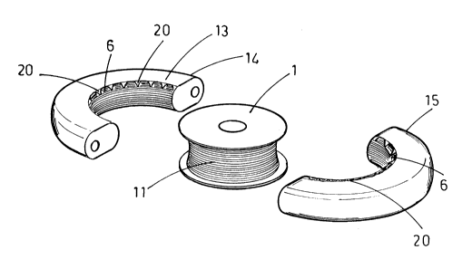
figure 5 is an exploded perspective view of parts
which can be used to make up a grinder according to
the invention;
figure 6a, 6b, 6c, 6d, 6e, 6f, 6g, 6h, 6i, 61 and
6m are examples of slab edges obtained using the
invention;
With reference to the figures, the invention
essentially comprises a banded grinder 10 for
working an edge 4 of a slab 5 of marble, granite and
the like.
The grinder 10 comprises a main body 1 made in metal
and axially keyable on a rotary chuck 2 and having a
lateral surface 3 shaped complementarily to the edge
4 of a slab 5.
The grinder 10 comprises a tract of abrasive tape 6
superposed on a lateral surface 3 of the main
21~514~
; body 1 and ring-wound thereon, and closed at
opposite ends 7 of said ,3brasive tape 6.
~we~l7 ~aid al-,rasivr- tape 6 and said 1atel`3l
surface 3 of tl~ main body 1 ~see figure 3), .3
05 la~l~ 11 of clastically deformable material, rnacl-
ot rubber or an ._l,~stomer having like
Ch31`aC~ tiC~, i5 interpositioned. Thi_ layeu~ ll
adhereJ both to the lat u~31 surface 3 of the main
; body l alld to tlle abrasive tape 6 such th3~ said
lo main body 1 and said abras-ive tape 6 are r;ndr-red
501 i~ll y r~_cipl-~oc~311 y col~_tr~ail~ed.
The layer 11 of elastically deformable material
covers the opposite ends 7 of the abrasive tape 6,
incorporating them in a banded strip 12 proYided
with a continuous abrasive surface 16 (see figure
. 2).
Figure 4 shows how the abrasive tape 6, before the
final construction of the grinder 10, ;5 provided
with a plurality of cuts 20 made at 1ateral edges
9 thereof and having the aim of creating an
optimal adaptation of the lateral surface 3 of the
main body 1 of the grinder 10 when said main body
1, as shown in figures 1, 2 and 3, exhibits curved
generatrices shaped complementarily to the edge 4
of the slab 5.
' -
21~51~0
-
The layer 11 of el,3stically deformable material,
in this case, covers also the cut lateral edges 9
of the strip of abrasive tape 6, incorporating
said cut lateral edges ~ into the banded strip 1
05 and cr.3ting a continuous surface thereof.
With reference to figure 5, a grinder 10 according
to the in~ ntion can be obtained with a procedure
utilizing parts as schematically represented in
the fi~ure and constituted by the following
operativ phases: ,
- po~itioning of at least one length of abrasive
tape ~ on an internal surface 13 of heated half
dies 14 and 15, which internal surface 13 is
shapcd complementarily to the lateral surface 3 of
~aid main body 1;
- spreading of a layer 11 of elastically
deformable material in semi-liquid state Oll the
lateral surface 3 of the main body l, which layer
subsequently adheres to said lateral surface 3;
- closure of the two half-dies 14 and 15 about the
main body 1, such that the abrasive tape 6 sinlcs
into the layer 11 of elastically deformable
material;
- solidification of the layer 11 of elastically
deformable material with consequent intimate
21~51~D
: connection of the abrasive tape (63 and the la~er
11 of elastically deformable material.
The above-described proce3s utilizes a layfr 11 of
vulcanized rubber, and can be substituted with
05 equivalent re~ult3 and similar equipmellt using a
~ conventiollal injection process of the material to
: be us.-d for the layer 11.
The invention is susc~ptibl-- to numerous
variatîons and modification~, all entering within
th~ field of the inventive concept, which concept
is herein related to specific examples of an
embodiment of 3 grinder 11, as shown in figures 1,
2 and 3. The grinders realizable according to the
present invention can, however, exhibit variou~
geometrical shape~ and sizes for realizing, for
example, convex ~-dges, concave edges and/or mixed-
shape edges, som~ of which are illustrated in
figure 6.