Note: Descriptions are shown in the official language in which they were submitted.
2145151
The present invention relates for a filter for
aquariums.
One of such filters is disclosed, for example in the
German patent document DE-OS 40 13 324, and operates as an
alternating lifting-lowering filter. This operation based in
the known filter on the fact that each individual filter
compartment has at least one overflow suction lift device
which operates on the principle of the lift loop. Its inlet
is located at the bottom side and therefore substantially at
the height of the bottom of the filter compartment and its
outlet opens downwardly toward the following filter
compartment. The outlet of the overflow suction lift device
opens in the lowermost filter compartment in a bottom chamber
into the interior of the filter housing. With this design of
the filter, a multi-stage operational sequence of the
filtering is performed. The control of the cyclical lifting-
lowering process is performed without special mechanically
movable parts. For high filter outputs no limits is set. The
known filter is suitable predominantly as an inner filter,
while its use as an outer filter is also desirable. However,
certain adjustments are needed for this application. For this
purpose in the known filter an auxiliary chamber is formed
which forms a throughgoing passage with individual tubular
elements extending through the filter compartments located
- 3 -
_2145151
over one another to provide protection from a dry running of
the pump. It is connected with an upper water supply of the
filter so that when needed, unfiltered water flowing directly
from the aquarium tank can be flow into the auxiliary chamber.
The downwardly located outlet of this passage is controllable
by a float-controlled valve device. It is located in a bottom
chamber in the filter housing formed under the lowest filter
compartment and placed in a motor-driven suction pump having
a pressure side connected with the outlet pipe for supplying
back to the aquarium tank the filtered water aspirated from
the bottom chamber. The float-controlled valve device located
inside the bottom chamber starts operating only when the water
level in the bottom chamber, due to a defect or a faulty
operation, is so low that there is the danger that the pump
which aspirates water from the bottom chamber runs dry. The
valve device has a float ball arranged in a cage and floating
in the bottom chamber in the case of sufficient water level so
as to pump from below upwardly toward the downwardly located
outlet of the auxiliary chamber and thereby constantly closing
the same. Only in the case of a very low water level in the
bottom chamber and therefore faulty buoyancy for the float
ball it falls due to gravity force so that the outlet of the
auxiliary chamber is released and thereby a connection is
produced with the bottom chamber. Thereby the pump now can
aspirate the unfiltered water from the aquarium tank through
- 4 -
_2145151
the auxiliary chamber and through its outlet into the bottom
chamber to prevent a dry running. The auxiliary chamber with
the valve device forms in this filter an emergency device
which normally does not operate and has nothing to do with the
desired alternating lifting-lowering operation.
Another filter is disclosed in the German document
DE-PS 27 00 030 which also operates as an alternating lifting-
lowering filter, but however is formed not in the same way.
This filter is connected with the aquarium tank through a
supply conduit. It has only one filter compartment. A bottom
chamber is formed in the filter housing under the filter
compartment, and a reverse U-shaped conduit with a free
tubular end opens into the bottom chamber. A pump is provided
in the conduit and aspirates water accumulated there from the
bottom chamber to supply the water into the tank through a
return conduit leading toward the aquarium tank. For safety
reasons for the case of stoppage of the filter compartment, a
bypass conduit is provided between the space located above the
filter compartment, where the supply is performed, and the
bottom chamber. Therefore with the clogged filter
compartment, the upwardly supplied water can flow unfiltered
through the supply conduit downwardly into the bottom chamber.
During aspiration of the water from the bottom chamber through
the open end of one leg of the U-shaped structure, the water
level in the filter compartment lowers downwardly. The
- 5 -
_2145151
discharge quantity per unit time is greater than the supply
quantity per unit time. Because of this device, a lifting-
lowering operation is performed. The filter is however
complicated as to the device for actuating the lifting-
lowering function, since the reverse U-shaped tube connected
with the pump extends through the filter mass in the filter
compartment with both legs. In addition the filter mass in
the filter compartment is also pierced through by the bypass
conduit with concomitant problem arising when the one leg of
the U-shaped structure extends through the bypass conduit.
- 6 -
_215151
Accordingly, it is an object of the present
invention to provide a filter for aquariums which avoids the
disadvantages of the prior art.
More particularly, it is an object of the present
invention to provide a filter for aquariums, in which the
arrangement for activating the lifting-lowering operation is
designed simply and inexpensively, can be dismounted when
necessary in a fast and simply manner and replaced and
provides a high filter output.
In keeping with these objects and with others which
will become apparent hereinafter, one feature of the present
invention resides, briefly stated, in a filter for aquariums,
in which the auxiliary chamber is formed in an auxiliary
housing and supplied with filtered water after passing at
least one filter compartment in accordance with the principle
of communicating pipes, and has a valve opening which is
alternatingly closeable and openable by a valve closing member
of a valve device controlled by a float, wherein the valve
opening is provided in a passage which is connected with a
suction conduit.
Since the auxiliary chamber is located in an
auxiliary housing, it can be removed fast and simply when
needed for example for cleaning and then mounted again. The
lifting-lowering operation is obtained in this filter by a
214515.
float-controlled valve device in the auxiliary chamber for
providing a continuous exchange of the operation, so that the
filtered water is supplied into the auxiliary chamber.
Thereby the auxiliary chamber and the float-controlled control
device can be purified from dirt particles entrained in water,
since it is filtered before during the filtering process. The
filter is operation-reliable to a higher degree and is
characterized by a long operation. It provides a high
throughput and a high filtering efficiency.
In accordance with another feature of the present
invention the supply of the filter is formed of a passage
which extends through at least one filter compartment and
closed relative to it as well as open into a bottom chamber in
the housing located under the lowest filter compartment, and
the suction of the supplied water is performed from below and
from the bottom chamber through at least one filter
compartment upwardly with concomitant filtering.
Such a filter operates without a lifting-lowering
operation. The filter can be designed as a simple, compact
and price-favorable device and utilizes substantially the same
components as the first mentioned filter with the lifting-
lowering operation. Therefore both filters which have
different operations can be formed substantially with the same
components. This filter is simple and first of all
inexpensive, since it can be produced with at least
_ g _
CA 02145151 2001-O1-29
25641-16
substantially the same components as a filter with the lifting-
lowering operation. The costs are therefore substantially
reduced, since for manufacturing of individual components only
insignificantly modified tools are needed and therefore
additional tool costs are dispensed with.
In summary, this invention seeks to provide a filter
for aquarium, comprising: a housing with at least one filter
compartment for filter material; a supply through which water
is supplied from above into said filter compartment; a p°amp
which aspirates water after passing through said filter
compartment through a suction conduit and supplies the water
back into an aquarium; at least one auxiliary chamber supplied
with water and having an outlet; a float-controlled valve
device controlling said outlet of said auxiliary chamber and
being in fluid communication with said suction conduit; an
auxiliary housing in which said auxiliary chamber is provided,
said auxiliary chamber being supplied with water which has been
filtered after passing through said filter compartment, aaid
valve device being provided with a float-controlled valve
closing member; arid a passage which is connected with said
suction conduit and has a valve opening which is alternatingly
closeable and openable by said valve closing member of s<~id
valve device.
The novel features which are considered as
characteristic for the invention are set forth in particular in
the appended claims. The invention itself, however, both as to
its construction and its method of operation, together with
additional objects and advantages thereof, will be best
understood from the following description of specific
embodiments when read in connection with the accompanying
drawings.
- 9 -
2~45~.~,~
FIG. 1 is a view schematically showing a vertical
cross-section along the line I-I in FIG. 2 through a filter
for aquariums in accordance with the first embodiment of the
present invention;
FIG. 2 is a schematic side view with the vertical
section along the line II-II in FIG. 1;
FIG. 3 is a schematic plan view of the filter in
direction of the arrow III in FIG. 1, however without an
upwardly inserted closing device;
FIG. 4 is a schematic vertical section along the
line IV-IV in FIG. 5 of a filter for aquariums in accordance
with the second embodiment of the present invention;
FIG. 5 is a schematic side view with a vertical
section along the line V-V in FIG. 4; and
FIG. 6 is a schematic plan view in the direction of
the arrow VI in FIG. 4, however with a not inserted closing
device.
- 10 -
zl4~mz
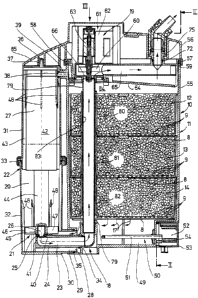
FIGS. 1 - 3 schematically show a filter 10 for
aquariums in accordance with the first embodiment of the
invention which is formed in particular as an outer filter to
be connected through corresponding hoses with a not shown
aquarium tank.
The filter 10 has a housing identified with
reference numeral 11 and having a substantially four-cornered,
in particular substantially parallelepipedic contour. The
housing 11 is composed for example of a synthetic plastic
material. At least one filter compartment for a filter
material is provided in the housing 11. In the shown
embodiment there are three filter compartments 12, 13, 14
arranged vertically over one another and provided with a
filter material such as for example a stone, gravel and the
like. The individual filter compartments 12, 13, 14 are
placed over one another and can be removed upwardly after one
another from the housing 11.
The filter compartment 12 is supplied with water
through a supply 15 from above in direction of the arrow 16,
which water is supplied from the not shown aquarium tank. The
water passes the filter compartments 12, 13, 14 in a vertical
direction in accordance with the arrow 17 and is aspirated
through a suction conduit 18 by the pump 19 and supplied back
into the not shown aquarium tank. The pump returns the
- 11 -
2145151
aspirated water through a corresponding conduit into the
aquarium tank.
The filter 10 operates as an alternating lifting-
lowering filter similar to the filter disclosed in the German
reference DE-OS 40 13 324. The specific operation of such an
alternating filter-lowering filter and in particular intense
oxygen enrichment provided by it is disclosed in the preceding
text, so that its repetition should be superfluous.
The filter 10 has at least one auxiliary chamber 20
supplied with water. The outlet of the auxiliary chamber 20
located below in FIG. 1 communicates with the suction conduit
18 and is controllable by a float-controlled valve device
identified with reference numeral 21.
A substantial feature of the filter 10 is that the
auxiliary chamber 20 is formed in an auxiliary housing 22 and
supplied with water in accordance with the principle of
communicating pipes, which water is filtered after passing the
compartments 12, 13, 14. Only such water arrives in the
auxiliary chamber 20 which has been already filtered.
The auxiliary chamber 20 has a passage 23 formed in
a tubular portion 24 which for example is cornered or round,
and connected with the suction conduit 18. The passage 23 in
the auxiliary chamber 20 has a valve opening 25 cooperating
with a valve closing member 26 of the valve device 21 and
openable and closeable by the valve closing member. The valve
- 12 -
214~15~
closing member is controlled by a float 27 arranged in the
auxiliary chamber 20 and connected with the valve closing
member.
The auxiliary chamber 20 has at least one supply
opening 28 so that the auxiliary chamber 20 communicates
through it with the housing 11 of the filter 10 and filtered
water is permanently supplied into the auxiliary chamber 20.
The supply opening 28 is connected with a conduit 29 formed
for example of a cornered or rounded tubular part 20 and
opening below the lowest filter compartment 14 into the
interior of the housing 11.
The tubular portion 24 in the passage 23 extends
into the interior of the tubular part 30 and is surrounded by
the latter at a distance so as to form for example a radial
passage of the conduit 29. The passage 23, in particular the
tubular portion 24 and/or the conduit 29, in particular the
tubular part 30, are formed of one piece with the auxiliary
housing 22 as shown in FIG. 1. The tubular portion 25 and the
tubular part 30 extend substantially horizontally, while the
remaining part of the auxiliary housing 22 extends
substantially vertically. The auxiliary housing 22 is tubular
and composed of two coaxially connected tubular halves 31 and
32. The lower tubular half 32 has a one-piece, substantially
rectangularly extending tubular portion 24 and the outer
tubular part 30. Both tubular halves 31, 32 are releasably
- 13 -
2145151
connected with one another, and the outer tubular half 31
engages from above with the inner end in the lower tubular
half 32. Both tubular halves 31, 32 are connected by a
connecting device 33, for example a ring, with interposition
of a seal.
The auxiliary housing 22 is releasably placed on the
housing 11 of the filter 10 and connected with it. The
housing 11 of the filter 10 is provided on a lower end of the
suction conduit 18 in FIG. 1 with a first connecting part 34
and further with a concentric second connecting part 35. Each
connecting part 34, 35 is tubular and corresponds to the
diameter of the tubular portion 24 or the tubular part 30.
The tubular portion 24 is connected with its end with
interposition of a seal with the first closing part 34 and in
particular is insertable into the latter. The tubular part 30
is connectable with its end with interposition of a seal to
the second closing part 35, in particular is insertable in the
latter. In this manner, the connection of the auxiliary
housing 22 with the housing 11 of the filter 10 is provided in
the lower region. The upper end of the auxiliary housing 22
in FIG. 1 has a pin-shaped projection 36 engaging into an
upper receptacle 37 of the housing 11 in a form-locking
manner. In this upper end region the auxiliary housing 22 has
a ventilating opening 38 in the wall of the tubular half 31
for connecting the auxiliary housing 22 to an upper
- 14 -
_2145151
ventilating pipe 39 of the housing 11, which opens into the
interior of the housing 11. Here also the connection is
performed releasably and by means of a plug-connection with
interposition of a seal. Therefore the auxiliary housing 22
is connectable with the housing 11 releasably with the housing
11 to sealingly form the corresponding passages.
The valve opening 25 is formed in a wall 40,
preferably in the upper wall of the passage 23, in particular
of the tubular portion 24. The passage 23, in particular the
tubular portion 24, also has at least one bypass opening 41
for permanently connecting the passage 23 with the auxiliary
chamber 20 in the auxiliary housing 22 and for aspirating
through the suction opening 18 a minimal water suction
quantity. Therefore the dry running of the pump 19 is
prevented. It can be seen that the valve opening 25 or the
passage 23 has a substantially greater throughflow cross-
section than the bypass opening 41. The throughflow cross-
section of the valve opening 25 is determined relative to that
of the bypass opening 41, so that with consideration of the
float 27 and the valve closing member 26, in particular the
buoyancy of the latter, the alternating lifting-lowering
operation is provided. This operation will be explained in
detail later on.
The float 27 is composed of a cylindrical body 42 of
relatively light material with high buoyancy properties, and
- 15 -
214511
swimmingly held in the auxiliary chamber 20. The cylindrical
body 42 has a cross-section which for example is only
insignificantly smaller than the cylindrical inner chamber 43
of the tubular auxiliary housing 22, in particular the tubular
halves 31, 32. The float 27, in particular the cylinder body
42 carries a coaxial support 44 extending downwardly in FIG.
1, and as the valve closing member 26 a coaxial cylinder
element 48 is formed of one piece or can be inserted into the
support and mounted in it. The support 44 is formed for
example as a rod. A guiding element 46 is held on the support
44 near the valve closing member 26, in particular the
cylinder element 45. It is composed for example of a guiding
disc 47 which is centered and guided in a substantially
cylindrical inner chamber 43 of the tubular auxiliary housing
22. The float 27, in particular the cylindrical body 42 also
is centered and guided in the interior of the auxiliary
housing 22. Inner guiding parts 44 are provided for guiding
the same, and formed for example as guiding rods located in a
peripheral direction for example at identical peripheral
angular distances.
The housing 11 of the filter 10 has an outwardly
closed bottom chamber 49 under the lowermost filter
compartment 14. The filtered water is supplied into the
bottom chamber 49 after passing the filter compartments 12,
13, 14. The auxiliary chamber 20 permanently communicates
- 16 -
2145152
with the bottom chamber 49 through the supply opening 28 of
the conduits 29, in particular the tubular part 30.
A heating device 40 is arranged in the bottom
chamber 9 when needed by the user in accordance with the first
embodiment of the invention. It has in particular an
electrical heating cartridge 51. The housing 11 of the filter
10 has a hollow chamber 59 provided at the height of the
bottom chamber 29 on an outer peripheral side and closeable by
a cap 53. A holder of the heating device 50 and an electrical
or electronic control device 40 for the heating device 50
schematically shown in FIG. 1 are received in the hollow
chamber 52.
If no heating device 50 is needed for the filter 10,
it can be dispensed with together with the control device 54.
The cap 53 can be fixed in this case, for example by glueing,
welding and the like. The construction of the filter 10
provides the possibility for installing an electrical heating
device 50 and a control device 54 later on when needed.
Each filter compartment 12, 13, 14 has a bottom 8
formed as a filtering element and provided with passages 90.
It is formed for example as a grate.
The housing 11 of the filter 10 is composed of two
parts. It has a substantially cup-shaped lower part 55 and a
cover 56 placed on it. The filter compartments 12, 13, 14 are
insertable in the lower part 55 and releasably retained in it.
- 17 -
21451~~
The cover 56 serves for upwardly closing the lower part 55 and
for this purpose can be placed on it and releasably fixed to
it. The cover 56 is connectable with the lower part 55
releasably by a closure member located on the lower part 56
non-removably, for example by a closure bracket. An axially
compressible seal 57 is arranged between the cover 56 and the
lower part 55 and can be formed as a shaped sealing ring. The
seal 57 is received in a groove 55 of the cover 56, which
opens toward the lower part 55. An upper edge part 59 of the
lower part 55 can be substantially form-lockingly engaged in
the groove 58 which contains the seal 57 during placement of
the cover 56.
The cover 56 and/or the lower part 55 and/or the
auxiliary housing 22 are composed of a synthetic plastic
material. The cover 56 contains at least one part of the
suction opening 18. In the cover-side region of the suction
conduit 18, an impeller 66 of the pump 19 is located. The
cover 55 has the pump 19 in a special region. The pump is
connected with an electric motor 61 for driving the impeller
60, which is composed of a stator 62 and a rotor 63. A
substantially horizontal outlet passage 65 extends in the
cover 56 above a cover wall 64 which limits a lower side of
the cover. The outlet passage 65 forms a part of the suction
conduit 18. The cover wall 64 in the region of the impeller
60 of the pump 19 located above, is provided with at least one
- 18 -
2145151
suction opening 66 communicating with the outlet passage 65 of
the suction conduit 18.
The cover 56 further has a supply passage 67 as a
part of the supply 15. The supply passage 67 opens into a
supply opening 68 provided in the cover wall 64. In addition
to the supply passage 67, the cover 56 has a ventilating
passage 69 which opens toward the lower side of the cover and
has an end side ventilation opening 70 provided in the cover
wall 64 and opening there. The ventilation passage 69 is
designed so that when not needed, such as for example in the
second embodiment shown in FIGS. 4 - 6, it is closed or
closable, for example by a blind plug 71 schematically shown
in FIG. 5.
The outlet passage 65 provided in the cover 56
and/or supply passage 66 and/or ventilation passage 69 each
have a receptacle 72, 73, 74 correspondingly in the cover 56,
which serve as a connection of the insertable outlet pipe 75
or supply pipe 76 or ventilating pipe 77 arranged for example
in a connecting device 78.
It can be seen from FIG. l, that the cover wall 64
raises inclinedly from the right outer side to at least a
suction opening 66 under the impeller 60. The cover 56,
depending on the design of the filter 10, is in a position as
shown for example in FIGS. 1 - 3 for -the first embodiment.
Instead it can be in another position as shown for example in
- 19 -
~~~51.5
the second embodiment of FIGS. 4 - 6 and turned relative to
the first position by 180° inside the cover plate, to be
placed on the lower part 55. The cover 56 is useable
simultaneously with two different embodiments of filter 10 and
110.
In the first embodiment of the filter 10 in FIGS.
1 - 3 a pipe 79 is connected with at least one suction opening
66 in the region under the impeller 60 in the cover wall 64.
The pipe 79 extends approximately completely over the height
of the lower part 55 and a part of the suction conduit 18.
The pipe 79 passes through the filter compartments 12, 13, 14
and closes them relative to one another. Each filter
compartment 12, 13, 14 has a tubular part 80, 81, 82 which is
one piece with it. With the placement of the filter
compartments 12, 13, 14 over one another they are connected
with one another and form a throughgoing tubular passage 83.
The pipe 79 extends through the tubular passage 83. The pipe
79 with its lower end in FIG. 1 is connected with a first
closing part 34 of the housing 11 in which the end of the pipe
79 engages. In this manner the inner passage of the pipe 79
is connected with the passage 23, in particular the tubular
portion 24, and forms with it a part of the suction opening
18.
The supply opening 68 in the cover wall 64 freely
opens into the space 84 provided between the cover wall 64 and
- 20 -
214151
the lower part 55 in its upper region. For ventilating the
auxiliary chamber 20 it communicates through the ventilation
opening 38 and the ventilation pipe 39 with the auxiliary
chamber 20, and for ventilation is ventilated outwardly
through the ventilation opening 70 and the ventilation passage
69 and communicates with the surrounding area through the
ventilation pipe 77 and a further not shown hose connected
with it. The space 84 is supplied through the supply opening
68 with water which flows through the supply pipe 76 and the
supply passage 67 from the aquarium tank, so that the water
can pass successively from above downwardly through the filter
compartments 12, 13, 14 and can be filtered there.
The filter 10 in accordance with the first
embodiment shown in FIGS. 1 - 3 operates as follows. The
water supplied from the aquarium passages through the filter
compartments 12, 13, 14 and lows into the bottom chamber 49.
Through the supply opening 28 of the conduit 29, the auxiliary
chamber 20 is connected with the interior of the housing 11 in
form of a communicating pipe, so that the water also is
accumulated in the auxiliary chamber 20. The water quantity
supplied to the filter 10 through the supply opening 68 is
greater than the water quantity which is aspirated with the
closed valve device 21 in FIG. 1 through the bypass opening 41
into the passage 23 and then through the supply conduit 18 by
the pump 19. Due to this, the in-flowing water raises the
- 21 -
2145151
water level in the housing 11 of the filter and
correspondingly in the auxiliary chamber 20. The water level
is raised therefore in the system. When with the raising
water level the buoyancy of the float 28, in particular the
cylindrical body 42, is sufficiently high, the float 28 floats
high and the valve closing member 26 is lifted over the
support 44, so that the valve opening 25 in the wall 40 of the
tubular portion 24 is released. Thereby the auxiliary chamber
20 can be emptied suddenly through the valve opening 25 having
a relatively great throughflow cross-section and through the
passage 23 and the suction conduit 19. The water level in the
housing 11 and in the auxiliary chamber 20 drops. The
lowering operation is therefore performed. This sudden
emptying of the housing 11 and the auxiliary chamber 20 is
obtained since the valve opening 25 is formed so great that
with the released valve opening 25, a greater water quantity
can pass through than the water quantity supplied through the
supply opening 68 of the supply 15. The dropping water level
in the housing 11 and in the auxiliary chamber 20 leads to the
situation that the float 27 together with the valve closing
member 26 lower until the valve closing member 26 closes again
the valve opening 25 as shown in FIG. 1. This closing step is
supported at the end by the suction action of the pump 19.
The valve device 21 is now closed. The cycle starts
again in that, the water which flows in through the supply 15
- 22 -
-,...
provides a continuously raising water level in the housing 11
and in the auxiliary chamber 20, which corresponds to the
lifting operation.
The filter 10 in this construction is compact,
operationally reliable, and assembled from only a few
inexpensive and functionally reliable components. For
cleaning purposes or for similar reasons, the cover 56 can be
released fast and simple from the lower part 55 and removed.
Therefore the laterally arranged auxiliary housing 22 can be
removed without problems. Also, the filter compartments 12,
13, 14 can be lifted in the same simple way and removed
upwardly. The pipe 79 is fixedly mounted either in the region
of the suction opening 66 of the cover 56 so that during
removal and tightening of the cover 56 it is automatically
removed with it, or it is just blocked so that during lifting
of the cover 56 with the remaining pipe 79, the pipe 79 is
pulled out upwardly. In the above described filter 10 it is
advantageous when the housing 11 and the auxiliary chamber 20
is composed of a transparent material, and therefore the
constant lifting-lowering operation and thereby the
disturbance-free operation of the filter 10 can be observed
from outside.
As can be seen from FIG. 3, the cover 56 has a
laterally extending part 85 projecting over the upper end of
the auxiliary housing 22. This part can be formed as a
- 23 -
214151
separate element which is mountable on the cover 56 when
needed so that the part 85 is placed on the cover 56 when a
filter 10 in accordance with the first embodiment of FIGS. 1
-3 is provided with the above discussed auxiliary housing 22
and the other components in their cooperation.
A filter 110 according to the second embodiment is
shown in FIGS. 4 - 6. It differs from the first embodiment in
that in the filter 110 there is no auxiliary housing 22 with
all components which perform the above described lifting-
lowering operation. The cover 56 can be designed without the
part 85. While the cover 56 in the first embodiment is formed
of one piece with the part 85, the cover 56 of the second
embodiment of FIGS. 4 - 6 is different in that there is no
part 85 in the cover.
The housing 111 of the filter 110 in accordance with
the second embodiment differs from the housing 11 of the first
embodiment in that, in the region of the bottom chamber 49,
the first connecting part 34 and the second connecting part 35
are dispensed with. In other aspects, the housing 111
corresponds to the housing of the first embodiment, so that it
is not described in detail to avoid repetitions. This is true
for the cover 56 and the filter 110 shown in FIGS. 4 - 6. The
latter is placed on the lower part 55 in a position which is
turned by 180° in the cover plane, when compared with the
first embodiment. A filter plate 186 is inserted in the
- 24 -
~- 214 515 ~,
housing 111 above under the space 84 and can be formed for
example as a perforated plate 186, a grate plate and the like,
to cover the uppermost filter compartment 12.
The filter 110 in accordance with the second
embodiment does not operate in accordance with the lifting-
lowering principle, but instead operates differently than the
filter 10. The supply 15 in the filter 110 is formed by a
passage 183 which passes through the filter compartments 12,
13, 14 and is closed relative to them. It opens in the bottom
chamber 49 located under the lowermost filter compartment 14.
The aspiration of the supplied water is performed here from
below and from the bottom chamber 49 through the lower filter
compartment 14, the next filter compartment 13, and through
the upper filter compartment 12 upwardly in correspondence
with the arrows. The water is filtered on its way through the
corresponding filter compartments 4, 13, 12.
With the cover 56 turned by 180 ° in the cover plane,
this operation is performed in that in this position at least
one suction opening 66 shown in FIG. 4 in the cover wall 64
opens freely into the space 84, and the water is aspirated
from it after passing the filter compartments 14, 13, 12 and
the filter plate 186.
When compared with the first embodiment, this is
obtained in that the pipe which is connected with at least one
suction opening 66 of the first embodiment is dispensed with
- 25 -
2145151
in the filter 110.
With the cover 56 in its position turned by 180°,
the supply 15 is formed as follows. The supply opening 68 in
the cover wall 64 has a special pipe 187 which is for example
inserted in it. The pipe 167 extends into the tubular passage
183 formed by the pipes 80, 81, 82 of the compartments 12, 13,
14 which are seated over one another. In this way the supply
15 extending from above downwardly through the filter
compartments 12, 13, 14 is provided as shown in FIGS. 4 and 5.
It is closed from the surrounding area and leads to the bottom
chamber 49.
Since in the filter 110 in accordance with the
second embodiment there is no ventilation pipe 39 in the
region of the lower part 55 and in the cover 56 the
ventilation passage 69 is not needed, it can be blocked by the
mentioned blind plug 71 or in another way, for example
simultaneously with the molding of the cover 56 or the
connecting device 168. This differs from the connecting
device 78 of the first embodiment in that a special hose
connection for producing the connection to the ventilation
pipe 77 and the ventilation passage 69 can be dispensed with.
Air which must collect in the space 84 under the
cover wall 64 is forced with the increasing water level int he
housing 111 positively due to the inclined construction of the
cover wall 64 in FIG. 4 to the right and into the region in
- 26 -
- 2145151
which at least one suction conduit 66 is located. It
communicates with the outlet passage 65 as a part of the
suction conduit 18. It is therefore guaranteed that the air
accumulated in the space 84 is always aspirated through the
outlet passage 65 of the suction conduit 18 and escapes
outwardly.
It will be understood that each of the elements
described above, or two or more together, may also find a
useful application in other types of constructions differing
from the types described above.
While the invention has been illustrated and
described as embodied in a filter for aquariums, it is not
intended to be limited to the details shown, since various
modifications and structural changes may be made without
departing in any way from the spirit of the present invention.
Without further analysis, the foregoing will so
fully reveal the gist of the present invention that others
can, by applying current knowledge, readily adapt it for
various applications without omitting features that, from the
standpoint of prior art, fairly constitute essential
characteristics of the generic or specific aspects of this
invention.
What is claimed as new and desired to be protected
by Letters Patent is set forth in the appended claims.
- 27 -