Note: Descriptions are shown in the official language in which they were submitted.
. 214S328
-
LIQUID FUEL LANTERN WITH ELECTRONIC IGNITION
Norris Richard Long
Backqround
This invention relates to liquid fuel burning appliances,
and, more particularly, to a liquid fuel lantern which is
equipped with an electronic ignition system.
Liquid fuel lanterns for camping and outdoor use are well
known and are described, for example, in United States Reissue
Patent No. 29,457, which is owned by The Coleman Company, Inc.
Liquid fuel which is used in such lanterns can be Coleman fuel,
white gas,~unleaded gasoline, etc.
In conventional liquid fueled lanterns such as the ones
which Coleman has offered for many years, fuel is contained in a
pressure vessel or fuel tank into which air is pumped under
pressure. As described in-United States Reissue Patent No.
29,457, the fuel tank is equipped with a dip tube which extends
to nearly the bottom of the tank. The dip tube is closed at the
bottom with the exception of a small diameter orifice through
which fuel is allowed to enter. The dip tube has an internal
conduit which is open at the bottom and which communicates with
the upper part of the fuel tank above the maximum intended fuel
level. The dip tube orifice can be partly blocked by insertion
of a needle which is suitably connected to the fuel control
system so as to cause it to partly block the orifice during the
lighting cycle and to leave the orifice unblocked during the
normal burn cycle. The upper end of the dip tube is connected
through a valve system to a generator. The generator is a metal
tube which passes into a venturi tube which is connected to one
or more catalytic mantles. Fuel is discharged at high velocity
from an orifice at the end of the generator into the venturi
where air is aspirated and mixed and fed to the catalytic mantle
as a combustible mixture for burning.
Before the lantern is lit, the generator is cool, and fuel
which flows through the generator is not vaporized. The
214~328
unvaporized fuel which is discharged through the generator
orifice is not readily ignitable at the mantle. To overcome
this problem, a dip tube needle can be used to partly block the
fuel entry orifice. This creates a pressure imbalance within
the dip tube which permits pressurized air to flow through the
passageway inside of the dip tube from above the fuel. This
pressurized air mixes with the liquid fuel and moves with it to
be discharged from the generator orifice. The fuel/air mixture
which is discharged from the generator orifice consists of a
fuel-vapor-laden air and atomized droplets of fuel which can be
ignited at the mantle by a lit match.
After the fuel/air mixture which flows into the mantle is
ignited, the generator will eventually be heated sufficiently to
vaporize the fuel which flows through the generator. The fuel
control system can then be adjusted to move the needle in the
fuel entry orifice of the dip tube so that only fuel flows
through the dip tube to the generator.
U.S. Patent Nos. 4,870,314, 4,691,16, and 3,843,311
describe propane or LP lanterns which are equipped with
piezoelectric ignition devices. Rather than using a lighted
match, the LP gas is ignited by a spark which is generated by
the piezoelectric device.
Liquid fuel lanterns are more difficult to light than LP
lanterns. LP gas is gaseous at atmospheric pressure and
temperature and is easily ignited by a spark, even under cold
conditions.
On the other hand, liquid fuel is a liquid at atmospheric
pressure and temperature. It is therefore more
difficult to provide automatic spark ignition of the fuel/air
mixture of a liquid fuel appliance, especially under cold
conditions. As the fuel/air mixture flows into the mantle, it
mixes with more air which makes the fuel mixture leaner. The
lean fuel mixture is more difficult to light with a sparking
device, and the difficultly increases as the ambient temperature
decreases.
Summary of the Invention
This invention enables a liquid fuel lantern to be easily
--2--
- 214~328
ignited by a sparking device. A pilot tube conveys fuel
directly from the burner assembly to the ignition device, and
the fuel which flows out of the pilot tube is richer than the
fuel which flows out of the burner and reaches the ignition
device. The spark ignites a flame at the end of the pilot tube,
and the flame ignites the fuel which flows out of the burner.
Description of the Drawing
The invention will be explained in conjunction with an
illustrative embodiment shown in the accompanying drawing, in
which --
Fig. 1 is a side elevational view of a lantern which isequipped with an electronic ignition system in accordance with
the invention;
Fig. 2 is a side elevational view of the other side of the
lantern of Fig. l;
Fig. 3 is a front elevational view of the lantern,
partially broken away;
Fig. 4 is a front elevational view, partially broken away,
of the burner assembly and ignition electrode;
Fig. 5 is a side elevational view of the burner assembly
and ignition electrode;
Fig. 6 is a fragmentary sectional view of the upper portion
of the pilot tube;
Fig. 7 is a front elevational view of the pilot tube;
Fig. 8 is a bottom plan view of the pilot tube;
Fig. 9 is an enlarged elevational view of the ignition
electrode; and
Fig. 10 is a top plan view of the spark generator assembly
as would be seen along the line 10-10 of Fig. 2.
Description of Specific Embodiment
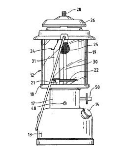
Referring to Figs. 1-3, the numeral 12 designates generally
a liquid fuel lantern. With the exception of the electronic
ignition system which will be described hereinafter, the lantern
is a conventional Coleman lantern. Such lanterns are described,
for example, in United States Reissue Patent No. 29,457.
The lantern includes a fuel tank or fount 13 which also
2145~2~
serves as the base for the lantern. The tank includes a fill
spout 14 and an air pump 15.
A cylindrical collar 17 and a pan 18 are supported by the
fuel tank. The pan supports a cylindrical globe 19. A heat
shield 20 includes three legs 21 which are supported by the pan
and a circular flat plate 22.
A metal burner assembly 24 extends upwardly within the
globe and conducts fuel from the fuel tank 13 to a pair of
catalytic mantles 25. Only one of the mantles is illustrated in
Figures 1-3. A ventilator cover 26 is mounted on top of the
globe and is secured to a threaded stud 27 (Figs. 4 and 5) on
the burner assembly by a screw knob 28.
The metal burner assembly 24 includes a generator tube 30
which communicates with the fuel tank and an inlet tube 31 (see
also Figs. 4 and 5). The bottom of the inlet tube extends
through the heat shield plate 22 and pan 18, and ambient air can
flow into the open bottom end of the inlet tube through openings
in the collar 17. The upper end of the generator tube 30
extends through an opening 32 (Fig. 4) in the inlet tube, and a
conventional fuel orifice or jet nozzle is mounted on the upper
end of the generator. The diameter of the inlet tube is reduced
above the fuel jet to provide a venturi which aspirates air into
the open bottom end of the inlet tube.
The inlet tube 31 is connected to a generally cylindrical
burner top 33 (Figs. 3 and 4). The burner top is formed from an
inverted top cup 34 and a bottom plate 35 which is crimped
around the cup to provide an internal chamber 36 (Fig. 4). A
pair of outlet tubes 37 are connected to the burner top on
either side of the inlet tube 31. Each outlet tube terminates
in an outwardly flared bottom end 38 which is adapted to support
one of the mantles 25.
A metal pilot tube 40 is connected to the bottom plate 35
of the burner top and extends to a position adjacent one of the
mantles 25. The main portion of the pilot tube is cylindrical,
and the bottom end is deformed or flattened to provide an
elongated oval opening or slit 41 (Fig. 8). The upper end of
the pilot tube includes a circumferential rib 42 (Fig. 7) which
abuts the bottom plate 35 of the burner top, and the top of the
` 2145328
tube is flared over the bottom plate 35 (Fig. 6) to secure the
pilot tube.
An electrode 44 is spaced slightly from the bottom end of
the pilot tube to form a spark gap of about 3/16 inch. The
electrode is mounted in an insulator 45, and the insulator is
supported by the heat shield plate 22. A wire 45 connects the
electrode 44 to a spark generator assembly 46 (Fig. 10) which is
housed within the collar 17.
Spark generating devices of the type illustrated in Fig. 10
are conventional and well known. The device is powered by a AAA
battery 47 and is actuated by a pushbutton 48 which extends
through the collar 17. When the pushbutton is depressed, a
spark is generated at the spark gap between the electrode 44 and
the metal pilot tube 40.
Another type of spark generator device which could be used
is a manually operated piezoelectric device such as the devices
described in U.S. Patent Nos. 4,870,314 and 4,691,136.
Operation
Before the lantern is operated, the liquid fuel within the
tank is pressurized with air by the air pump 15. Flow of fuel
from the tank through the generator tube 30 is controlled by a
valve and a valve knob 50 (Figs. 1-3). When the valve is
opened, the instant lighting system of the lantern causes a
fuel/air mixture to flow from the fuel tank through the
generator tube. The fuel/air mixture flows at high speed
through the generator jet, and as the fuel/air mixture flows
through the venturi of the inlet tube 31, additional air is
aspirated into the mixture through the open bottom end of the
inlet tube 31.
The fuel/air mixture flows into the chamber 36 of the
burner top 33. The main portion of the fuel/air mixture flows
out of the chamber through the two outlet tubes 37. A minor
portion of the fuel/air mixture flows through the pilot tube 40.
When the spark generator is actuated by the pushbutton 48,
a spark jumps from the electrode 44 to the pilot tube 40 and
ignites the fuel/air mixture which flows from the pilot tube.
The ignited gas in turn ignites the fuel/air mixture which is
--5--
214~28
flowing from the outlet tubes 37 into the mantles 25. The
lantern is thereafter operated in the conventional manner.
After the generator tube 30 is heated sufficiently to
vaporize the fuel, the instant lighting system is adjusted so
that only fuel flows through the generator tube. Primary
combustion air will still be incorporated with the fuel when the
fuel flows through the jet into the venturi of the inlet tube
31. A small portion of fuel will continue to flow through the
pilot tube during operation of the lantern and will cause a
small flame at the end of the pilot tube. However, the majority
of the fuel will burn within the catalytic mantles.
Since the spark is generated directly at the exit of the
pilot tube 40, the fuel/air mixture is relatively rich in fuel
and can be ignited easily by the spark even in cold weather. On
the other hand, if the electrode were positioned so that the
fuel/air mixture flowing through one of the mantles were
ignited, the fuel/air mixture would incorporate additional air
as it flowed out of the outlet tube and before it could be
ignited by the spark. The resulting fuel/air mixture would be
leaner and more difficult to ignite, especially in cold weather.
While in the foregoing specification a detailed description
of a specific embodiment of the invention was set forth for the
purpose of illustration, it will be understood that many of the
details herein given may be varied considerably by those skilled
in the art without departing from the spirit and scope of the
invention.