Note: Descriptions are shown in the official language in which they were submitted.
~ WO94/10372 2 1 4 S 5 ~ 9 PCT/US93/09651
TOP CIRCULATION LINE COOLING FOR A
MODIFIED COOK DI~P;~l~.K
BACKGROUND AND SUMMARY OF THE INVENTION
During conventional continuous chemical pulp
production, particularly in kraft cooking, the
entire cooking liquor (e.g. white liquor) charae i~
added to the feed system, which includes the hjgh
pressure feeder and the circulation line to t~le top
of the digester either with or without an
impregnation vessel. However over the last decade
two significant advances have taken place in
continuous chemical pulp production technology which
have changed this. First the MCC~ digesters, and
method, developed by Kamyr, Inc. of Glens Falls, New
York, added white liquor into a central
recirculation loop within the digester.
Subsequently, EMCC~ digesters and processes, also
developed by Kamyr, Inc., provided for introduction
of white liquor into the bottom (wash) circ-1lation
loop. While these digesters and systems h~ve been
commercially successful because they enhance the
quality of the pulp produced, one unexpected problem
resulted from the introduction of the cooking ]iq11or
at multiple points, instead of the entire white
liquor charge being added to the feed system.
According to the present invention, it has been
determined that, in continuous digesting systems
where a plurality of feed points for the cooking
liquor are provided, since the volume of relatively
cool cooking liquor supplied to the feed system is
reduced, higher temperatures occur in the top
circulation line, i.e. the line returning liquid
wo 94~1037l 15 ~ ~ ~ PCT/US93/0965 ~
separated from the chips in the top of the digester
to the high pressure feeder (either with or witho-lt
an impregnation vessel). This increases the
potential for hydraulic hammering due to liquor
flashing in the line, introducing loading on the
adjacent equipment and piping, and providing
potential hammering which can damage the high
pressure feeder and adjacent piping and equipme~t.
According to the present invention, the tempe~ature
of the liquid in the recirculation line, and
circulation line, is kept low enough so as to avoid
hydraulic hammering due to liquor flashing.
According to the present invention there is
provided a method of feeding comminuted cellulosic
fibrous material to a continuous digester having a
plurality of feed points for cooking liquor, and
utilizing a high pressure feeder. The method
comprises the following steps: (a) Entraining
comminuted cellulosic fibrous material in li~lid to
produce a slurry, and feeding the slurry to the top
of the digester using the high pressure feeder. (b)
Adding some cooking liguor to the slurry as part of
the liquid entraining the material. (c) Separating
some of the liquid from the slurry at the top of the
digester. And, (d) recirculating the separated out
liquid from the top of the digester LO the high
pressure feeder. According to the invention, the
hydraulic hammering can be prevented when using one
or both of the following techniques: the
recirculating liquid can be cooled (by passing it
into heat exchange relationship with a cooler
liguid), and/or the cooking liquor may be cooled
before it is added to the slurry (e.g. by flashing
the cooking liquor to reduce its temperature, and
~ W094/10372 214 5 5 2 9 PCT/US93/09651
produce flashed steam which may subsequently be used
in an evaporator). If flashing of the cooking
liquor is utilized, typically it is flashed when it
has a temperature of about 9OC, and the temperature
thereof is reduced by at least about 10C, which can
be enough -- either singly or in combination with
cooling of the recirculating liquid from the top of
the digester -- to avoid hydraulic hammering. The
vacuum required for such flashing is provided
through the connections made to the evaporator
system.
According to another aspect of the present
invention, a cellulosic pulp producing system is
provided which comprises the following elements: A
substantially upright continuous digester. A high
pressure feeder. A circulating line operatively
extending from the high pressure feeder to the top
of the digester. A recirculating line operatively
extending from the top of the digester to the high
pressure feeder. A separator for separating liquid
from a slurry containing cellulosic fibrous material
and liquid, the separator disposed at the top of the
digester and connected to the recirculating line.
Means for adding cooking liquor to slurry being
transported by the high pressure feeder to the top
of the digester. And, heat exchanger means
operatively disposed in the recirculating line for
reducing the temperature of liquid being
recirculated from the digester to ihe high pressure
feeder.
The system may also comprise means for sensing
the temperature of liquid in the recirculating line,
means for regulating the flow rate of coolant to the
heat exchanger means (e.g. a valve), and means for
WO94/10372 PCT/US93/096 ~
2 ~ 2 9
controlling the coolant flow rate regulating means
in response to the temperature sensing. An
impregnation vessel may be disposed in the
recirculating and circulating lines betwëen the high
pressure feeder and the continuous digester, in
which case the heat exchanger means is typically in
the recirculating line between the impregnation
vessel and the high pressure feeder.
According to yet another aspect of the present
invention a cellulose pulp producing system is
provided comprising: A substantially upright
continuous digester. A high pressure feeder. A
circulating line operatively extending from the high
pressure feeder to the top of the digester. A
recirculating line operatively extending from the
top of the digester to the high pressure feeder. A
separator for separating liquid from a slurry
containing cellulosic fibrous material and liquid,
the separator disposed at the top of the digester
and connected to the recirculating line. Means for
adding cooking liquor to slurry being transported by
the high pressure feeder to the top of the
digester. And, means for cooling the cooking li~uor
before supplying it to the means for adding cooking
liquor. The cooking liquor cooling means preferably
comprises a flash tank, including a steam disch~rge,
and the steam discharge is operatively connected to
evaporators.
It is the primary object of the present
invention to provide a method and apparatus for
avoiding hydraulic hammering or the like in modern
continuous digesting systems in which a plurality of
feed points for cooking liquor are provided. This
and other objects of the invention will become clear
~ WO94/10372 2 1 4 5 ~ 2 9 PCT/US93/09651
from an inspection of the detailed description of
the invention and from the appended.
BRIEF DESCRIPTION OF TEE DRAWINGS
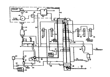
FIGURE l is a schematic view of a first
embodiment of an exemplary system according to the
present invention;
FIGURE 2 is a schematic view of a modified form
of the embodiment of FIGURE l; and
FIGURE 3 i 5 a schematic view of a system for
cooling of white liquor by flashing the white
liquor, according to another embodiment of the
present invention.
DETAIr.l;~D DF-~CRTPTION OF THE DRAWINGS
FIGURE l schematically illustrates a first
embodiment of apparatus according to the present
invention, for feeding comminuted cellulosic fibrous
material (e.g. wood chips) to a continuous digester,
and treating the wood chips to produce pulp, ~uch a~
sulfate pulp, sulfite pulp, or the like.
The conventional components of the appar~tus of
FIGURE l include the air lock lO and chips bin ll
which receive chips from a source and then pass them
through a chip meter 12 and low pressure feeder 13
into a horizontal ~teaming ves~el 14, the chips
being discharged into a chute 15 connected to a
conventional high pressure feeder 18. A high
pressure pump l9 is connected to one port of the
high pressure feeder 18, while a low pressure pump
WO94/10372 PCT/US93/096 ~
2 ~ 6
20 is connected to another port thereof. The pump
20 also is operatively connected to a sand separato7-
21, which in turn is connected to an in-line dr~iner
22. A level tank 23 and a pump 24 aref~lso
provided, and white liguor from a source 25 (or a
like cooking liquor depending upon which pulping
process is utilized) is ultimately entrained with
the chips discharged by the high pressure feeder
18. Line 26 connected to the pump 24 leads to the
top of an upright continuous digester, and white
liquor is also added at one or more additional
points to the digester 29, such as to line 27
connected through a pump to the line 28.
Additional conventional components of the
system of FIGURE l include the line 30 for
circulating cellulosic fibrous material (chips)
entrained in liquid to the top of the digester 29,
at which point some of the liquid is separated from
the chips/liquid slurry by the conventional top
separator 3l, and then is returned by the top
circulation line 32 to the high pre-ssure inlet pump
l9 of the high pressure feeder 18. Heaters 3:3, 34,
and 35 are provided for heating liguid withdrawn
from various screens associated with the digester
29, which liquid is then circulated back to the
digester 29 to effect cooking or the like. Also
black liquor is withdrawn from the digester 29 ~nd
flashed in the first and second flash tanks 36, 37.
An outlet device 38 discharges pulp from the bottom
of the digester 29 into a discharge line 39, after
which the pulp is passed on to subseguent treatment
stages, such as washing, storage, and bleaching
stages.
~ WO94/10372 214 ~ ~ 2 9 PCT/US93/09651
The conventional components of the system
illustrated in FIGURE 1 comprise a single vessel
hydraulic "MCC"~ Kamyr, Inc. digester system. Since
white liquor is added at different points in the
system, the temperature of the slurry or liquid in
the lines 3~, 32 may increase undesirably so th~t it
flashes into steam and causes hammering, and perhaps
damage, in and to the high pressure feeder 18 and to
line 30. In order to avoid this adverse
consequence, according to the present invention the
recirculating li~lid in line 32 is cooled so th~t
the temperature of the slurry in the high pre~sure
feeder 18 and being fed in line 30 to the top of the
digester 29 is low enough to avoid hydraulic
hammering due to liquor flashing.
The apparatus cooling means for accomplishing
the desired result according to the invention is
shown generally within the dotted line box 42 in
FIGURE 1. It includes a conventional heat exchanger
43 through which the recirculating line 32 passes
between the top separator 31 and the low pressure
inlet pump 19 for the high pressure feeder 18.
Coolant, which can be any available mill water, or
cooler wash water from upstream brown stock wasllers
or the like (e.g. liquid in route to recovery) or
any process stream that could benefit from heating,
passes through line 45 into heat exchange
relationship with the hot liquor in the line 32,
thereby significantly cooling the liquor in line
32. The coolant passes through an automatically
controlled valve 46, controlled by flow controller
47, which receives input from the temperature
indicator 48 operatively connected to the line 32.
The temperature indicator 48 senses the temperature
WO94/10372 PCT/US93/096
2 l~S~ ~9 8
of the liquid being recirculated in line 32, and
adjusts the flow of cooling liquid from coolant
source 44 through valve 46, depending upon the
sensed temperature. In this way, the temperature in
the line 32 is lowered to the extent necessary to
prevent hydraulic hammering, but yet is maintained
high enough so that substantial amounts of energy
are not wasted, or a great deal of additional energy
need not be supplied to the chips to heat them to
cooking temperature.
The apparatus illustrated in FIGURE 2 is the
same as that illustrated in FIGURE 1 except that it
is for a two vessel hydraulic Kamyr MCC~ digester
system. In the FIGURE 2 embodiment components
comparable to those in the FIGURE 1 embodiment are
illustrated by the same reference numeral only
preceded by a "1".
The only significant difference in the
embodiment of FIGURE 2 is that a conventional
impregnation vessel 50 is provided in the
circulating and recirculating lines 130, 132. That
is the circulating line 130 extends from the }~i~h
pressure feeder 118 to the top separator 51 of the
impregnation vessel 50, and recirculating liq~lid is
withdrawn through line 52 at the top of the
impregnation vessel 50. The chips slurry disch~rged
by the outlet device 53 at the bottom of the
impregnation vessel 50 passes the chips in
circulating line 54 to the top of the digester 129,
while liquid recirculated from the top of the
digester 129 in line 132 passes back to the vessel
50. In this case, the high pressure feeder 118 is
protected by the cooling mechanism 142 being
provided in line 52, as illustrated in FIGURE 2.
~ W O 94/10372 PC~r/US93/09651
2145~29
..
That is the cooling means 142 (substantially
identical to cooling means 42) is between the
impregnation vessel 50 and the high pressure feeder
118 in the circulating and recirculating loops for
supplying slurry to and withdrawing liguid from the
continuous digester 129.
In addition to the apparatus according to the
invention illustrated in FIGURES 1 and 2 (namely the
cooling means 42, 142), according to the present
invention another mechanism (FIGURE 3) may be
utilized for lowering the temperature of the liquids
associated with the high pressure feeder 18, 118,
and thereby avoiding hydraulic hammering.
Alternatively, in some situations the cooling means
42, 142 may not be necessary and the mechanism
illustrated in FIGURE 3 may be used in its place.
FIGURE 3 illustrates a mechanism for cooling
the white li~lor that is supplied to the chips that
are passing in the circulating line to the top of
the digester 29, 129, taking into account that the
volume of this white liquor is much less than in
conventional digesters (that is those without t]le
MCC~ or EMCC~ process improvements of Kamyr,
Inc.).
As illustrated in FIGURE 3, hot white liquor
from the pulp mill recausticization and white ]iquor
storage facilities, typically at a temperature of
about 90C, i8 flashed in a conventional flash tank
61. The vacuum required for this flashing is
provided by a vacuum pump in the attached
evaporator. The flashed steam, at approximately
80C, goes into line 63, while the cooled white
liquor passes into line 25 (that is the cooled white
liquor becomes the source of white li~uor
W094/10372 PCT/US93/096 ~
2 ~ 2 9
illustrated at the left hand bottom of FIGURE 1).
The temperature of the white liquor is reduced by at
least 10C by flashing.
The steam in line 63 from flash tank 61 is
combined with steam from green liquor flashing, or
other steam sources, illustrated schematically at 64
in FIGURE 3, and then passes via line 65 to a
plurality of evaporators 66 through 69. Thus the
steam from white liquor flashing is utilized to
supplement the heat requirements of evaporators,
such as the evaporators 66 through 69.
It will thus be seen according to the present
invention that the temperature in the top
circulation line of an MCCTM or EMCC~ digester is
controlled so as to avoid hydraulic hammering.
While the invention has been herein shown and
described in what is presently conceived to be the
most practical and preferred embodiment thereof it
will be apparent to those of ordinary skill in the
art that many modifications may be made thereof
within the scope of the invention, which scope is to
be accorded the broadest interpretation of the
appended claims so as to encompass all equivalent
structures and methods.