Note: Descriptions are shown in the official language in which they were submitted.
PATENT
44407-222
AN IMPLANTABLE ATRIAL DEFIBRILLATOR HAVING
AN INTERMITTENTLY ACTIVATED PACING MODALITY
BACRGROUND OF THE INVENTION
The present invention generally relates to an automatic
implantable atrial defibrillator for delivering cardioverting
or defibrillating electrical energy to the atria of a human
heart. The present invention is more particularly directed to
such an atrial defibrillator which has an intermittently
activated pacing modality for assisting the heart in returning
to normal sinus. rhythm immediately following each attempted
cardioversion of the atria. Because the pacing function is
only activated for a finite period of time following each
attempted cardioversion, the pacing function is provided
without undue power consumption of a depletable power source,
such as a battery, within the atrial defibrillator.
Atrial fibrillation is probably the most common cardiac
arrhythmia. Although it is not usually a life threatening
arrhythmia, it is associated with strokes thought to be caused
by blood clots forming in areas of stagnant blood flow as a
result of prolonged atrial fibrillation. In addition,
patients afflicted with atrial fibrillation generally
experience palpitations of the heart and may even experience
dizziness or even loss of consciousness.
Atrial fibrillation occurs suddenly and many times can
only be corrected by a discharge of electrical energy to the
heart through the skin of the patient by way of an external
defibrillator of the type well known in the art. This
treatment is commonly referred to as synchronized
cardioversion and, as its name implies, involves applying
electrical defibrillating energy to the heart in synchronism
with a detected electrical activation (R wave) of the heart.
The treatment is very painful and, unfortunately, most often
only results in temporary relief for patients, lasting but a
few weeks.
Drugs are available for reducing the incidence of atrial
fibrillation. However, these drugs have many side effects and
many patients are resistant to them which greatly reduces
their therapeutic effect.
Implantable atrial defibrillators have been proposed to
provide patients suffering from occurrences of atrial
fibrillation with relief. Unfortunately, to the detriment of
such patients, none of these atrial defibrillators have become
a commercial reality.
Implantable atrial defibrillators proposed in the past
have exhibited a number of disadvantages which probably has
been the cause of these defibrillators from becoming a
commercial reality. Two such defibrillators, although
represented as being implantable, were not fully automatic,
requiring human interaction for cardioverting or
defibrillating the heart. Both of these defibrillators
require the patient to recognize the symptoms of atrial
fibrillation with one defibrillator requiring a visit to a
-2-
physician to activate the defibrillator and the other
defibrillator requiring the patient to activate the
defibrillator from external to the patient's skin with a
magnet.
Implantable ventricular defibrillators for applying
defibrillating electrical energy to the ventricles of the
heart are well known and have been commercially available for
a number of years. Because ventricular fibrillation is life
threatening, resulting in unconsciousness in just a few
seconds and leading to death in just a few minutes,
implantable ventricular defibrillators are fully automatic for
detecting ventricular fibrillation and quickly applying the
defibrillating electrical energy to the ventricles. Such
defibrillators are quite large in physical size as compared to
the size of a pacemaker, for example, because of the rather
large battery and storage capacitors required for providing
defibrillating energies of ten joules of more. Due to their
rather large size, these devices must be implanted in an
abdominal region of the human body.
Any form of implantable device must be powered by a
portable, depletable power source, such as a battery. When
the battery is depleted of its energy, it is necessary to
explant the device and implant a replacement. As a result,
for an implantable device to be considered commercially
viable, it is generally believed that the device should have
-3-
a predicted lifetime of a number of years, such as five years,
for example.
Predicted lifetimes of less than five years for
ventricular defibrillators have not diminished the commercial
nature of these devices because ventricular fibrillation is
life threatening. However, since atrial fibrillation is not
generally considered to be life threatening, it is generally
believed that atrial defibrillators should have lifetimes on
the order of five years to render such devices commercial in
nature. To further enhance the commercial nature of these
devices, it is desirable to limit the physical size of an
atrial defibrillator to the size of a large pacemaker, for
example, to permit the atrial defibrillator to be implanted,
like a pacemaker, within the chest of the human body. While
predicted lifetime and physical size have not adversely
affected the commercial nature of ventricular defibrillators,
such constraints have probably been the cause of an atrial
defibrillator not being commercially available to date.
It has long been believed that as much electrical energy
is required to cardiovert or defibrillate the atria of the
heart as is required to cardiovert or defibrillate the
ventricles of the heart, on the order of ten joules or more.
Furthermore, episodes of atrial fibrillation occur much more
frequently than do episodes of ventricular fibrillation. As
a result, due to the contemplated required cardioverting or
defibrillating energy levels for cardioverting or
CA 02145592 2000-08-02
defibrillating the aria of the heart and the predicted
required frequency of delivering such energies, it has long
been believed 'that an implantable atrial defibrillator would
either have an unreasonably short and commercially
unacceptable predictE~d lifetime or a battery and storage
capacitor of such a l~~rge size that the atrial defibrillator
would be too :Large in physical size. Fortunately, a lead
system has been discovered for an atrial defibrillator which
greatly reduce; the amount of energy required to defibrillate
l0 or cardiovert the atria. This lead system is fully described
in U.S. Patent No. 5,279,291 which issued on January 18, 1994
for "Method for Atria:l Defibrillation", which is assigned to
the assignee of the present invention. The lead system
described in that patient includes a first electrode in the
:l5 coronary sinus or great cardiac vein of the heart and a second
electrode in the right atrium or superior vena cava of the
heart. With such electrode placement, cardioverting energy
applied to there eleci~rodes is substantially confined to the
atria, reducing the amount of energy required to cardiovert
:!0 the atria to on the ooder of one joule or less.
It has also J.ong been believed that an atrial
defibrillator, like a 'ventricular defibrillator, should charge
its storage capacitor ~~uickly to permit essentially immediate
cardioversion. Such quick storage capacitor charging places
l5 an extreme drain on the battery thereby further limiting the
- 5 -
CA 02145592 2000-08-02
predicted lifei~ime of an implantable atrial defibrillator and
further adding to the heretofore perceived non-commercial
nature of these devices.
Recently, it has been recognized that, since atrial
S fibrillation is not life threatening, the storage capacitor of
an atrial defibrillator need not be charged as quickly as the
storage capacitor oi: a ventricular defibrillator. That
recognition has led to another improvement in an atrial
defibrillator i:ully described in U.S. Patent No. 5,251,624 for
"Pulse Generator for Use in an Implantable Atrial
Defibrillator" which issued on October 12, 1993, which is
assigned to the assigr..ee of the present invention. The pulse
generator described :ln that patent conserves battery power
while still providing adequate electrical energy to cardiovert
or defibrillai~e the atria of the heart to arrest atrial
fibrillation. This is achieved by charging the storage
capacitor comparatively slowly to minimize drain on the
defibrillator battery but in sufficient time to arrest the
atrial fibrillation. In accordance with the described
preferred embodiment, this is accomplished by converting the
rather low voltage of the battery to a pulsating high voltage
of 300 to 400 'volts, Eor example, with a flyback transformer
having a primary wi:zding coupled to an oscillator which
provides the primary winding with a high frequency, low duty
:?S cycle input. 13y virt~ie of this arrangement, sufficient
- 6 -
electrical energy for cardioverting or defibrillating the
heart is stored in the storage capacitor without imposing a
high drain on the defibrillator battery. Even though a minute
may be required to fully charge the storage capacitor, this is
sufficient to arrest the atrial fibrillation and bring comfort
to the patient.
Further, as is well known in the art, the sinus node of
the heart is the normal pacemaker of the heart and may be
rendered dysfunctional by the application of cardioverting
electrical energy to the atria. When such sinus node
dysfunction occurs following an attempted cardioversion, the
heart is caused to pause for a few seconds. It is also known
that patients who suffer from atrial fibrillation may have an
increased risk of sinus node dysfunction due to disease and/or
drug therapy. Hence, it has been proposed in the past to
provide an in~plantable atrial defibrillator with a demand
ventricular pacing modality for pacing the ventricles when
required.
Unfortunately, demand pacing requires the maintenance of
a pacing output in readiness for pacing and the sensing of
heart activity, and more particularly, R waves of the heart.
This sensing is generally provided by one or more sense
amplifiers and at least one R wave detector.
While sense amplifiers and R wave detectors used to sense
heart activity and pacer output circuits are generally
perceived as consuming little power when held in a fully
!.
biased readiness condition, the power consumed by these
circuits under such conditions in a continuous manner over
periods of months and years as is contemplated by the prior
art, is considerable. Hence, the power consumed by
continuously maintaining a demand pacing modality of an
implantable atrial defibrillator in readiness is still another
factor which limits the predicted lifetimes of these devices.
The present invention overcomes the power consumption
problem of maintaining continuous demand pacing readiness in
a fully automatic atrial defibrillator. This is accomplished
by effectively providing power to the pacing circuitry for
only a short finite time period following each attempted
cardioversion. As a result, demand pacing is provided during
those times when sinus node dysfunction may be present while
conserving precious battery power. In fact, by practicing the
present invention as described hereinafter, a twenty percent
(20%) savings in battery power may be realized.
SUMMARY OF T8E INVENTION
The present invention provides an implantable atrial
defibrillator for applying cardioverting electrical energy to
the atria of a human heart in need of cardioversion and
thereafter pacing the heart in a demand mode. The atrial
defibrillator includes first detecting means for detecting
atrial activity of the heart, atrial fibrillation detecting
means responsive to the atrial activity detected by the first
_g_
CA 02145592 2000-08-02
detecting means for dE~termining when the atria of the heart
are in need of cardioversion, and cardioverting means
responsive to the atz-ial fibrillation detecting means for
applying the cardioverting electrical energy to the atria of
the heart when the atz-ia are in need of cardioversion. The
atrial defibrillator fvirther includes pacing means for pacing
the heart in a demand code, depletable power source means for
providing electrical power to the first detecting means, the
atrial fibrillation dei~ecting means, the cardioverting means,
and the pacing means, and means.for enabling the pacing means
in response to.t.he card.ioverting means applying cardioverting
electrical ener~3y to the atria and thereafter disabling the
pacing means in respon~~e to the occurrence of a predetermined
event for conserving t)ze depletable power source means.
The present. inven~~ion further provides a method for use
in an implantable atria. defibrillator including a depletable
power source for apply:eng cardioverting electrical energy to
the atria of a human heart in need of cardioversion and
thereafter pacing the heart in a demand mode. The method
includes the steps of detecting atrial activity of the heart,
determining responsive to the detected atrial activity of the
heart if the atria are in fibrillation, and applying
cardioverting electrical energy to the atria of the heart if
the atria are in fib~:illation. The method includes the
further steps of providing pacing means for pacing the heart
in a demand mode, enatling the pacing means in response to
-9-
applying cardioverting electrical energy to the atria of the
heart, and disabling the pacing means in response to the
occurrence of a predetermined event for conserving the
depletable power source.
BRIEF DESCRIPTION OF THE DRAWINGS
The features of the present invention which are believed
to be novel are set forth with particularity in the appended
claims. The invention, together with further objects and
advantages thereof, may best be understood by making reference
to the following description taken in conjunction with the
accompanying drawing, in the sole figure of which like
reference numerals identify identical elements, and wherein
the sole figure is a block diagram of a fully implantable
atrial defibrillator embodying the present invention.
DETAINED DESCRIPTION OF THE PREFERRED EMBODIMENT
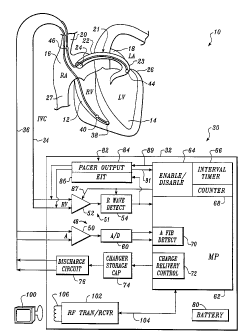
Referring now to the sole figure, it illustrates a fully
implantable atrial defibrillator 30 embodying the present
invention shown in association with a schematically
illustrated human heart 10 in need of atrial fibrillation
monitoring and potential cardioversion of the atria. The
portions of the heart 10 illustrated in the sole figure are
the right ventricle 12, the left ventricle 14, the right
atrium 16, the left atrium 18, the superior vena cava 20, the
coronary sinus channel 21, which, as used herein, denotes the
-10-
__
coronary sinus 22 and the great cardiac vein 23, the coronary
sinus ostium or opening 24, the left ventricular free wall 26
and the inferior vena cava 27.
The atrial defibrillator 30 generally includes an
enclosure 32 for hermetically sealing the internal circuit
elements of the atrial defibrillator to be described
hereinafter, an endocardial first lead 34, and an
intravascular second lead 36. The enclosure 32 and first and
second leads 34 and 36 are arranged to be implanted beneath
the skin of a patient so as to render the atrial defibrillator
30 fully implantable.
The endocardial first lead 34 preferably comprises an
endocardial bi-polar lead having electrodes 38 and 40 arranged
for establishing electrical. contact with the right ventricle
12 of the heart 10. The electrodes 38 and 40 permit bi-polar
sensing of ventricular activations in the right ventricle.
The electrodes 38 and 40 further provide for pacing the
ventricles 12 and 14 in a manner to be described hereinafter
in accordance with the present invention. As illustrated, the
lead 34 is fed through the superior vena cava 20, into the
right atrium 16, and then into the right ventricle 12.
The second lead 36 generally includes a first or tip
electrode 44 and a second or proximal electrode 46. As
illustrated, the second lead 3 6 is flexible and arranged to be
passed down the superior vena cava 20, into the right atrium
16, into the coronary sinus ostium 24, and advanced into the
-11-
~14~~9'~
coronary sinus channel 21 of the heart near the left side
thereof so that the first or tip electrode 44 is within the
coronary sinus channel 21 either within the coronary sinus 22
adjacent the left ventricle 14 and beneath the left atrium 18
or most preferably within the great cardiac vein 23 adjacent
the left ventricle 14 and beneath the left atrium 18. The
electrodes 44 and 46 are spaced apart such that when the first
electrode 44 is positioned as described above, the second
electrode 46 is in the right atrium 16. The first electrode
44 together with the second electrode 46 provide bi-polar
sensing of heart activity in the atria 16 and 18. The first
electrode 44 and the second electrode 46 further provide for
the delivery of defibrillating electrical energy to the atria.
Because the first electrode 44 is located beneath the left
atrium 18 near the left ventricle 14 and the second electrode
46 is within the right atrium 16, the electrical energy
applied between these electrodes will be substantially
confined to the atria 16 and 18 of the heart 10. As a result,
the electrical energy applied to the right ventricle 12 and
left ventricle 14 when the atria are cardioverted or
defibrillated will be minimized. This greatly reduces the
potential for ventricular fibrillation of the heart to be
induced as a result of the application of defibrillating
electrical energy of the atria of the heart.
Within the enclosure 32, the atrial defibrillator 30
includes a first sense amplifier 50, a second sense amplifier
-12-
5
52, and an R wave detector 54. The first sense amplifier 50
forms a first detecting means 48 which, together with the lead
36 to which sense amplifier 50 is coupled, senses atrial
activity of the heart. The second sense amplifier 52 and the
R wave detector 54 form a second detecting means 51 which,
together with the lead 34 to which sense amplifier 52 is
coupled, detects ventricular activations of the right
ventricle of the heart.
The output of the second sense amplifier 52 is coupled to
the R wave detector 54. The R wave detector 54 is of the type
well known in the art which provides an output pulse upon the
occurrence of an R wave being sensed during a cardiac cycle of
the heart.
The output of the first sense amplifier 50 is coupled to
an analog to digital converter 60. The analog to digital
converter 60 converts the analog signal representative of the
atrial activity of the heart being detected to digital samples
for further processing in a manner to be described
hereinafter.
The enclosure 32 of the atrial defibrillator 30 further
includes a microprocessor 62. The implementation of the
microprocessor 62 in accordance with this embodiment of the
present invention results in a plurality of functional stages.
The stages include an enable/disable stage 64, an interval
timer stage 66, a counter stage 68, an atrial arrhythmia
-13-
1.
detector in the form of an atrial fibrillation detector 70,
and a charge delivery and energy control stage 72.
The microprocessor 62 is arranged to operate in
conjunction with a memory (not shown) which may be coupled to
the microprocessor 62 by a multiple-bit address bus (not
shown) and a bi-directional multiple-bit databus (not shown).
This permits the microprocessor 62 to address desired memory
locations within the memory for executing write or read
operations. During a write operation, the microprocessor
stores data, such as time intervals or operating parameters in
the memory at the addresses defined by multiple-bit addresses
conveyed over the address bus and conveys the data to the
memory over the multiple-bit data bus. During a read
operation, the microprocessor 62 obtains data from the memory
at the storage locations identified by the multiple-bit
addresses provided over the address bus and receives the data
from the memory over the bi-directional data bus.
For entering operating parameters into the microprocessor
62, the microprocessor 62 receives such programmable operating
parameters from an external controller 100 which is external
to the skin of the patient. The external controller 100 is
arranged to communicate with a receiver/transmitter 102 which
is coupled to the microprocessor 62 over a bi-directional bus
104. The receiver/transmitter 102 may be of the type well
known in the art for conveying various information which it
obtains from the microprocessor 62 to the external controller
-14-
~~4~~9
100 or for receiving programming parameters from the external
controller 100 which the receiver/transmitter 102 then conveys
to the microprocessor 62 for storage in internal memory or in
the aforementioned external memory within enclosure 32.
The receiver/transmitter 102 includes a transmitting coil
106 so that the receiver/transmitter 102 and coil 106 form a
communication means. Such communication means are well known
in the art and may be utilized as noted above for receiving
commands from external to the implantable enclosure 32 and for
transmitting data to the external controller 100 from the
implanted enclosure 32.
To complete the identification of the various structural
elements within the enclosure 32, the atrial defibrillator 30
further includes a charger and storage capacitor circuit 74 of
the type well known in the art which charges a storage
capacitor to a predetermined voltage level, a discharge
circuit 76 for discharging the storage capacitor within
circuit 74 during a predetermined discharge time to provide a
controlled discharge output of electrical energy, when
required, to the atria of the heart, and a pacer 82 for
applying pacing electrical energy to the.ventricles of the
heart.
The discharge circuit 76 is coupled to the first
electrode 44 and the second electrode 46 of the second lead
36. This permits the application of the cardioverting or
defibrillating electrical energy to the atria.
-15-
The pacer 82 may be of the type well known in the art for
providing pacing electrical energy to the right ventricle 12
in a demand mode. The pacer 82 includes an output circuit 84
which is coupled to electrodes 38 and 40 of lead 34 for
applying the pacing electrical energy to the right ventricle
12. The pacer 82 further includes an escape interval timer 86
for timing an escape interval to permit the pacer 82 to
operate in a demand mode as well known in the art. The pacer
also utilizes, and hence includes, the sense amplifier 52 and
R Wave detector 54 for sensing activity of the right ventricle
and resetting the escape interval timer 86 when an R wave is
detected within-a timed escape interval.
Lastly, the defibrillator 30 includes a depletable power
source 80, such a lithium battery. The battery 80 provides
power to the electrical components of the atrial defibrillator
30.
At spaced apart times, as for example every 5 to 20
minutes, the microprocessor 62 enables the sense amplifier 52
and R wave detector 54, over control line 87 and sense
amplifier 50 and the analog to digital converter 60 to acquire
data representative of the activity of the heart which is
stored in the aforementioned memory (not shown).
The atrial fibrillation detector 70 then processes the
stored data to determine if the heart is experiencing an
episode of atrial fibrillation. If atrial fibrillation is
detected, the charge delivery and control stage 72 initiates
-16-
CA 02145592 2000-08-02
the storage of the cardioverting electrical energy within the
storage capacii:or of c:harger and storage capacitor circuit 74.
When the storage capacitor is fully charged, the
microprocessor then preferably initiates a safety protocol as
S fully described in U.S. Patent No. 5,207,219 which issued on
May 4, 1993 for Atria7. Defibrillator and Method For Providing
Interval Timing Prior to Cardioversion, which patent is
assigned to t:he assignee of the present invention. As
described in that patE:nt, the microprocessor 62 times the time
between successively detected R waves to time the cardiac
intervals of t:he heart. When a cardiac interval is timed
which exceeds a predetermined minimum time interval, the
microprocessor 62, through the discharge circuit 76,
discharges the storage capacitor of circuit 74 for a
predetermined discharge time to apply cardioverting electrical
energy to electrodes 44 and 46 of lead 36. This applies the
cardioverting electrical energy to the atria 16 and 18 of the
heart for cardioverting the atria.
After applying the cardioverting electrical energy to the
:ZO atria, the microprocessor 62, through the enable/disable stage
64, enables the pacer output 84 and escape interval timer 86
over control .Line 89. This begins the post-cardioversion
demand pacing of the heart. Pacing of the heart is enabled
for a finite time until the occurrence of a predetermined
:?5 event.
_ 1~ _
~14~~9
In accordance with a first embodiment of the present
invention, the predetermined event may be the completion of a
timing interval. To that end, the interval timer 66 may be
utilized for timing a time interval beginning immediately
after each cardioversion attempt and extending for a time of,
for example, 15 seconds to five minutes, and preferably one
minute. When the timer 66 completes the timing of the
predetermined time interval, the enable/disable stage 64 then
disables the pacer 82 by disabling the pacer output 84 and
escape interval timer 86 over control line 89 and disabling
the sense amplifier 52 and R wave detector 54 over control
line 87.
Alternatively, and in accordance with a second embodiment
of the present invention, the predetermined event may be the
completion of a predetermined number of cardiac cycles. To
that end, the counter 68 counts the intrinsic or natural R
waves of the heart and the pacing pulses issued by the pacer
output 84 for counting the cardiac cycles of the heart
occurring since the attempted cardioversion. When the counter
68 has counted a predetermined number of cardiac cycles, for
example between 15 and 300 cardiac cycles, and preferably 30
cardiac cycles, the enable/disable stage 64 then disables the
pacer output 84 and the escape interval timer 86 over control
line 89 and the sense amplifier 52 and the R wave detector 54
over control line 87 as previously described.
-18-
Most preferably, and in accordance with a third
embodiment of the present invention, the predetermined event
is the occurrence of a consecutive number of intrinsic cardiac
cycles of the heart. Here again, the counter 68 is utilized
but for counting only intrinsic R waves of the heart detected
by the sense amplifier 52 and the R wave detector 54. When
the pacer output 84 paces the heart, the pacer output 84
provides a reset signal over reset line 91 to reset the
counter 68. As a result, the count in counter 68 will
represent the last number of consecutive intrinsic or natural
cardiac cycles of the heart. When the count in counter 68
reaches a predetermined count, as for example between three
and ten intrinsic cardiac cycles, and preferably three
intrinsic cardiac cycles, indicating that the predetermined
number of consecutive intrinsic cardiac cycles have occurred,
the enable/disable stage 64 then disables the pacer output 84
and escape interval timer 86 over control line 89 and disables
the sense amplifier 52 and R wave detector 54 over control
line 87.
For enabling and disabling the pacer 82, the bias voltage
on the pacer output 84, escape interval timer 86, sense
amplifier 52 and R wave detector 54 may be switched between a
low bias voltage, rendering these circuits disabled and
inoperative, to a regular bias voltage, to effectively provide
power to these circuits for rendering these circuits enabled
and fully operative. In the disabled state, these circuits
-19-
~1~~~~
would consume little if any measurable power to conserve the
battery 80.
Alternatively, a solid state switch may be employed
between the battery 80 and each of the pacer output 84, the
escape interval timer 86, the sense amplifier 52, and the R
wave detector 54. When the pacer 82 is disabled, the control
lines 87 and 89 will turn the solid state switches off to
effectively disconnect these circuits from the battery. When
these circuits are enabled, the control lines 87 and 89 will
turn the solid state switches on to connect the circuits to
the battery. When the pacer is disabled, only the leakage
current through the solid state switches will consume power.
Unlike the prior art which contemplates continuous
enablement of demand pacing, the atrial defibrillator of the
present invention enables demand pacing during only a finite
time period following each attempted cardioversion. Hence,
not only does the present invention provide an atrial
defibrillator which provides demand pacing during the time
when sinus node dysfunction may be present, in addition, it
does so in a manner which conserves precious battery power.
In fact, by practicing the present invention, a twenty percent
(20%) savings in battery power may be realized.
While a particular embodiment of the present invention
has been shown and described, modifications may be made, and
it is therefore intended to cover in the appended claims all
-20-
such changes and modifications which fall within the true
spirit and scope of the invention.
-21-