Note: Descriptions are shown in the official language in which they were submitted.
21~~~~n
coRnL$ss, s~c$a w=~roow covet=xa
Field of the Invention
The present invention relates generally to the art
of spring motors useful for a variety of applications,
including venetian blinds and window shades. More
specifically the present invention relates to a system in
which lifting cords and cord locking mechanisms are
eliminated from shades or blinds. Still more
specifically, the invention relates to window covering
systems which employ one or more constant or consistent,
variable force springs to balance the weight of
accumulated window covering material, depending upon the
extent to which the blind or shade is raised or lowered.
The present invention also relates to motorized blinds
and shades.
flocnri rW i nn Of the Prior Art
Venetian blinds have been known for many years and
typically include a plurality of slats made from metal,
plastic, wood or other materials and supported by
ladders. Such blinds typically include a bottom bar and
a tilt mechanism to cause the slats to move from a
horizontal position to a nearly vertical position to open
_~l~soss
and close the blinds with respect to the passage of
light. It is also conventional with such systems to use
lifting cords coupled to the bottom bar, passing through
the slats and into mechanisms within the blind headrail.
The cord is used to raise the bottom bar, accumulating
individual slats as the bar is raised. Because of the
natural tendency of the bar and accumulated slat weight
to free fall, locking mechanisms are also commonly
employed with such prior art devices. Pleated and other
types of shades also include a bottom bar and similar
raising, lowering, and cord locking mechanisms.
Several attempts have been made to eliminate the
lifting cord locks, some of such attempts going back
nearly 140 years. See, for example, Bixler, U.S. Patent
No. 13,251, issued July 17, 1855 for "Inside Blinds."
U.S. Patent No. 2,420,301, issued May 13, 1947 to
Cusumano for "Venetian Blind" also employs a cone-shaped
member with grooves and an elongate coil spring. A
different device is shown in Pratt's U.S. Patent No.
2,324,536 issued July 20, 1943 for "Closure Structure."
In this device, tapes and coil springs are employed to
raise and lower a blind particularly suited for use in a
vehicle such as a train.
Other patents show various spring devices used with
venetian blinds, i.e. Cohn's U.S. Patent No. 2,390,826,
issued December 1l, 1945 for "Cordless Venetian Blinds,"
Etten's U.S. Patent No. 2,824,608, issued February 25,
1958 for-"Venetian Blirid";.U.S. Patent No. 2,266,160,'
issued December 16, 1941 to Burns for "Spring Actuated
Blind"; and U.S. Patent No. 2,276,716, issued March 17,
1942 to Cardona for "Venetian Blind."
Various attempts have also been made in the prior
art to motorize blinds and shades. In most of these
systems hardwiring is required because larger motors are
~1~~08fi
3 _
required to move the bottom rail and accumulated window
material.
None of the aforementioned patents disclose the use
of spring motors of the type disclosed herein to
eliminate the conventional pull cords and locks of
venetian blinds or shades in a simple and easily
adaptable mechanism having few components parts.
The present invention features a cordless blind or
shade in which a spring motor is used to eliminate
conventional pull cord and cord-lock mechanisms.
The present invention also features a system in
which either the spring strength or the number of spring
motors may be altered, depending upon the size of the
window covering. The invention further features
techniques for increasing the friction on the cords used
to raise and lower the blinds or shade to assist in
maintaining a desired position against any spring force
which may exist through the range of travel of the bottom
bar.
The present invention still further features a
system which is easy to adapt to a wide variety of blind
or shade designs and sizes and the capability of applying
spring, forces in a variety of ways and combinations.
A different feature of the present invention is the
use of spring motors and small electric motors to provide
highly desirable automatic or remote controlled
capabilities for shades and blinds.
How the present invention accomplishes these
features will be described in the following detailed
21~~08~
- 4 -
description of the most preferred embodiments, taken in
conjunction with the FIGURES which illustrate blind
systems, although shade applications are also enhanced by
the present invention. Generally, however, the features
are accomplished by employing constant force or
consistent variable force spring motors in a blind or
shade system, while eliminating conventional pull cord
and associated cord-lock mechanisms. The features~are
accomplished by using springs wound on drums, the springs
being of constant cross-section (constant force) or
varying in width, thickness, or both along their length
(variable force) whereby spring force imparted to a
coiled spring is transferred from one drum to another.
For these spring motors, such force is at its highest
level when the blind or shade is fully raised, i.e., when
the cords are supporting the full weight of the window
covering. The spring force is at its lowest point when
the window covering is fully lowered and, in the case of
blinds, the slats are being individually supported by
ladders, rather than by the cords, leaving only the
bottom bar to be supported by the cord. In constant
force systems, the spring force is substantially constant
1
throughout the range of movement of its shade or blind
bottom rack. The blinds and shades of the present
invention may be manipulated by the operator simply
grasping the bottom bar and urging it in an upward or
downward direction.
Ths features of the present invention are also
accomplished by providing selection criteria for the'
springs, to take into account the size and weight of a
particular blind or shade or by adding additional spring
motors for heavier or wider window coverings. To achieve
greater certainty in maintaining desirable spring forces,
in a most preferred, alternate form of the invention, the
spring motors are interconnected to ensure that they
operate in unison to provide a level action throughout
the range of blind or shade travel. All of these
2146086
- 5 -
features are accomplished in a blind or shade which will
remain in the position selected by the user and which in
a preferred embodiment may be motorized, e.g. by a small
remote controlled DC'motor. In an illustrated
embodiment, friction imparting devices are, if necessary,
used with the cords coupling the bottom bar and a spool
within the headrail.
FIGURE 1A is a perspective view of a spring storage
drum useful in one preferred form of the present
invention;
FIGURE 1B is a perspective view of output drum,
combined with a cord spool, useful in this preferred form
of the present invention;
FIGURE 2 is a schematic view of a spring motor
together with one form of friction imparting device;
FIGURE 3 is a schematic illustration of a
combination of three spring motors, with the cord spools
coupled together to ensure that all motors operate in
unison;
FIGURE 4A is a perspective view of a strip of spring
material varying in width along its length;
FIGURE 4B is a schematic view of the spring shown in
FIGURE 4A wound into a coil;
FIGURE 5A is a schematic view of a spring varying in
thickness along its length;
FIGURE 5B is a view of the spring of FIGURE 5A shown
in a coiled position;
21~608~
FIGURE 6 is a schematic representation of a blind in
the fully open position with the cord storage drum fully
wound and a spring wound on its storage drum, the system
thereby supporting the full weight of the slats and
bottom bar;
FIGURE 7 is a schematic illustration of the blind
shown in FIGURE 6, with the bottom bar in its fully
lowered position and illustrating how the'atorage drum
for the cords is substantially empty and the spring
substantially transferred from its storage drum to its
associated output drum; and
FIGURE 8A is a perspective view of a strip of spring
material being~generally uniform in cross section along
its length,
FIGURE 8B is a schematic view of the spring shown in
FIGURE 8A wound into a coil; and
FIGURE 9 is a view, similar to FIGURE 6, but showing
in schematic form a motor system for raising and lowering
the blind.
In the various FIGURES, like reference numerals are
used to indicate like components.
gF'~'AThED DESCRIPTION OF THE PREFERRED EMBODIMENTS
Before proceeding with the detailed description of
the preferred embodiments, several comments should be
made about the applicability and the scope of the present
invention. First, while venetian-type blinds are shown
in certain of the FIGURES, the types of materials from
which the blinds are made or the relative widths, heights
and the configuration of the headrail, bottom rail and
slats may vary widely. The present invention has
21460~~
applicability to a variety of such blinds. The present
invention is also useful with window shades of various
types since many shade designs also use lifting cords and
would benefit from the features of this invention.
Whenever blinds are mentioned herein, shades should be
considered a suitable alternative.
Second, while preferred types of springs are shown,
one varying in width, another varying in thickness and a
third being of constant cross-section, a combination of
the three could be employed. Other spring configurations
could also be used, in addition to those having a
rectangular cross-section. For example, springs with
round or oval cross-sections, decreasing along its length
(for a variable force spring) or a laminated spring could
also be employed.
Third, while one example is given of how to
interconnect a plurality of spring motors, other
techniques can be employed. For example, a gear system
can be employed instead of the illustrated bar. The
object of illustrative FIGURE 3 is to show how the spring
motors can be made to operate in unison for level raising
or lowering of the blind or shade, even if the lifting
forces are applied off center. Ideally, however, the
user should be instructed to apply the lifting or
lowering force at, or relatively near, the center of the
bottom rail to maintain desirable balance and to prevent
slack from being created in the lifting cords.
Proceeding now to a description of the FIGURES,
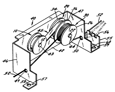
FIGURE 1 is a perspective view of one storage drum 10
useful in the preferred embodiment. Storage drum 10
includes an axial hole 12, a cylindrically-shaped spring
storage area 14, and a pair of walls 16 and 18 which
taper upwardly and outwardly from area 14. This
particular storage drum is especially suitable for a
spring which varies in width, as will be described later
214608
_8_
in this specification. Drum 10 will be referred to
herein as a storage drum, i.e. the drum on which the
spring is initially coiled. The drum 10 would have
parallel walls 16 and,l8 for other embodiments such as
for the springs illustrated in FIGURES 5A, 5B, 8A, and
8B.
Proceeding next to FIGURE 1B, an output drum is
shown generally at 20 to include an axial~hole 22, a
cylindrical body 24, and a pair of walls 26 and 28. A
hole 29 is provided on body portion 24, the purpose of
which will become apparent shortly. Output drum 20 also
includes a cord spool 30 having a central aperture (not
shown) coaxial with hole 22, a body portion 32, and a
pair of parallel side walls 34 and 36 defining an area
therebetween for storage of the lifting cords.
Proceeding next to FIGURE 2, the arrangement of the
devices in FIGURES 1A and 1B in a spring motor unit 40 is
shown. Motor unit 40 includes a bracket having a planar
back wall 42 onto which the storage drum 10 and output
drum 20 are rotatably mounted in a spaced apart
orientation. Axles 43 and 44 pass respectively through
the apertures 12 and 22 of the drums 10 and 20. From
FIGURE 2, it will be appreciated that output drum 20 is
located adjacent wall 42, with the cord spool 30 located
outwardly therefrom..
A spring is illustrated at 45 and is coupled between
storage drum i'0 and output drum 20. The~spring itself
will be described later. The spring motor unit 40 also
includes a pair of surfaces 46 and 47, which are parallel
to one another and perpendicular to surface 42, defining
a generally U-shaped enclosure for the two drums and the
cord spool. A hole 49 is provided in surface 46 and a
hole 50 is provided in surface 47, with lifting cords 52
shown passing through each toward the cord spool 30. The
illustrated motor unit 40 also includes another bracket
2~.4~~~;~
_ g _
component 55 spaced apart from surface 47 and including a
plurality of slots 56 in its upper edge. Solid and
dashed lines illustrate how the slots 56 may be used to
increase the tension'on the cord 52 traveling through
portion 47 toward cord spool 30.
Finally, two attachment areas 57 and 59 are shown in
FIGURE 2, with holes 58 and 60, respectively. The latter
are used for attachment of the bracket to~the blind head
bracket. Obviously, the location of the mounting holes
can vary widely, depending on the overall configuration
of the blind with which the spring force motor unit 40 is
to be used.
Before proceeding to more detailed descriptions of
the springs 45, reference should now be made to FIGURE 3,
showing schematically how a plurality of. spring motor
units 40 may be coupled together, e.g. by an elongate bar
62 rotatably coupled to each of the respective cord
spools 30 (or by gearing on the drums 10 and 20, not
shown). It will be appreciated from this drawing, which
is from a reverse perspective compared to that shown in
FIGURE 2, that the three spring motor units 40 will work
in unison and the bar 62 will compensate for minor
variations in spring forces which may exist for the
individual springs 45 and ensure an even winding of the
cords 52, even if the force to raise or lower the blind
is applied off-center.
Proceeding next to'the descriptions~of FIGURES 4A
and 4B, a preferred spring 70 is shown, again in
perspective form. Spring 70 includes a first narrower
end 72, a second wider end 74 and a coupling extension 75
having a hole 76 therein. The illustrated spring has a
constant thickness. Spring 70, in use, is wound onto the
storage drum in the configuration illustrated in FIGURE
48, i.e. with its narrower end coupled to body portion
14, and its wider end toward the outside. The extension
2146~~6
- 10 -
75 is attached to the body portion 24 of output drum 20
using hole 76 and any suitable fastener. The spring is
wound from one drum to the other in an opposite coil
orientation. In other words, as spring 70 is transferred
from the storage drum 10 to the output drum 20, the width
of the spring 70 between the two drums will decrease and
the spring will be wound oppositely to its original coil
shape.
Another embodiment of a spring useful in the
invention is shown in FIGURES 5A and 5B, i.e. a spring 80
having a varying thickness. Spring 8o has a thinner
first end 82, a thicker second end 84 having a width
equal to that of end 82, and a coupling extension 85
having a hole 86 therein. The preferred coil orientation
fox spring 80 is shown in FIGURE 5B, this time with the
thinner end 82 at the core of the storage drum 10 and the
thicker end 84 extending onto and around the output drum
20, using coupling extension 85 and hole 86. Again, the
orientation of the spring, as it is transferred from the
storage drum 10 to the output drum 20, is reversed.
While it has been mentioned earlier that springs of
different configurations may be employed for variable
force spring motors, it will now be more fully
appreciated that one variation would be to use a spring
which varies both in width and thickness. Also, a coil
spring of circular cross-section or a laminated spring
could be employed. The cross-section increasing from the
end attached to the storage drum l0 to the end attached
to the output drum 20.
Proceeding now 1:o FIGURE 6, the use of a spring
motor unit 40 for a blind system 90 is shown. Blind
system 90 includes a bottom bar 92, a headrail 94, and a
plurality of slats 95 located therebetween. The ladders
are not illustrated in these FIGURES but are conventional
and, in and of themselves, do not form part of the
21~6Q~3~
- 11 -
present invention. The cords for raising and lowering
bottom bar 94 are illustrated at 96 and 97 and are shown
extending through the slats and toward the cord spool 30,
which will be fully wound with cord when the blind is in
the position illustrated in FIGURE 6. Moreover, the
storage drum would be wound with most of spring 45 and
the output drum would be wound only to the extent
desirable to attach its end and to provide the desired
holding force.
Referring now to FIGURE 7, the bottom bar 92 is
shown in its fully lowered position with the individual
slats 95 spaced from one another and with the cords 96
and 97 unwound from cord spool 30. At this point, the
slats would be individually suspended from ladders (not
shown) attached to the headrail 94, so that their weight
is not being carried by the spring motor unit 40. It can
be observed that the spring 45 has been substantially
transferred from the storage drum 10 to the output drum
20, thereby decreasing the amount of force exerted on the
bottom bar. In an ideal situation, the spring force will
be just sufficient to prevent bottom bar 92 from self-
raising.
When it is desired to open blind system 90, the
bottom bar 92 is urged toward headrail 94, resulting in a
spring driven rotation of the cord spool to wind cords 96
and 97. The spring will rewind back to storage drum 10,
with an ever increasing level of force as the weight of
the bottom bar'92' and accumulating slats 95 continues to
increase. The operation is completed when the FIGURE 6
configuration is achieved.
While the present invention has been described in
connection with several illustrated embodiments, further
variations may now be apparent. For example, instead of
using only two cords (illustrated as 96 and 97 in FIGURES
~1~6086
.. - 12 -
6-7), additional cords could be used for wider blinds, as
required.
In connection with experiments done to date, one
suitable spring is made from Type 301 High-Yield
Stainless Steel and has a length of 87 inches and a
constant thickness of .005 inches. Its width increased
from .110 inches at its narrow end to .312 inches at its
wide end. For a coil diameter of .540 indhes, a
theoretical maximum torque of .650 pounds per inch was
created, and the theoretical torque minimum was .230
pounds per inch.
In another example, a spring strip of the same
length and material varied in thickness from .0029 inches
to .0054 inches with the same coil diameter. The
theoretical maximum torque was .819 pounds per inch,
while the torque at the bottom (minimum) is reduced to
.140 pounds per inch. It can be seen from these examples
that the spring motor provides a variable force which is
consistent in application, depending upon the particular
position of the bottom rail or member with respect to the
headrail. The theoretical forces may be readily
calculated using formulas which are available from spring
manufacturers in which the output force is determined by
the formula:
F- E.b.s3
2 4 ~12
where:
F = Output force
E = Modulus of elasticity
b = Width of spring strip
214G~8~
- 13 -
s = Thickness of spring strip
r = Constant coil radius.
It then becomes',apparent that as the width or
thickness varies from end to end of the strip, so also
will the resultant force.
FIGURES 8A and 88 show yet another embodiment of the
present invention, this time where the spY~ing 45 is a
constant cross-section spring 110 having a first end 112,
a second end 114, an extension 115 extending from the
second end, and a hole 116 in the extension. The coiled
form of spring 110 is shown in FIGURE 8B.
It has been found that in some applications, for
example applications where the blinds are short, or are
made from very light materials, or where friction
imparting devices are used with the cords that a constant
force spring may be entirely suitable. This is true
because while the weight exerted on the lifting cords 94
and 96 will vary as the blind is raised and lowered,
frictional forces are present which can be sufficient to
maintain the shade in any desired position without free
fall. This particular embodiment could be enhanced using
the friction imparting devices discussed in connection
with FIGURE 2. Accordingly, it can be readily seen that
the present invention has extremely wide application and
that the designer may make numerous choices depending
upon the particular size of the blind, its construction
materials, etc:
As with the other embodiments, several spring motors
employing springs 110 can be coupled together, e.g. as is
shown in FIGURE 3. Alternatively, a plurality of such
motors may be used which are not interconnected to one
another.
214608
- 14 -
FIGURE 9 is a view, similar to FIGURE 6, showing in
schematic form a motor system for raising and lowering a
blind. In order to facilitate understanding of the
invention, like elements will be identified by like
reference numerals in FIGURE 9 and FIGURE 6. Accordingly,
in FIGURE 9, a blind system 90 is illustrated having, a
spring motor unit 40 and cords 96, 97 for raising and
lowering bottom bar 92.
Also shown in FIGURE 9 are a drive motor 130, and a
control unit 132 for controlling operation of drive motor
130. Drive motor 130 is preferably an electrical motor
which can drive in two directions and is operatively
coupled with spring motor unit 4o by a coupling 131 to
apply a drive force in either of two directions to move
bottom bar 92 up or down. It is advantageous to use both
spring motor unit 40 and drive motor 130 so that the
force applied to blind system 90 by spring motor unit 40
augments and assists drive motor 130. Drive motor 130 may
be operatively coupled anywhere in the driving mechanism
of blind system 90. By such an arrangement a smaller,
cheaper, and more energy-efficient drive motor 110 may be
more advantageously employed with blind system 90 than
could be employed alone without spring motor unit 40.
Control commands may be provided to control unit 132
for controlling operation of drive motor 130 from a
remote position by hard-wired connection (not shown in
FIGURE 9) to a remote control unit such as remote control
unit 134. In the~alt~rriative, remote control unit 134 may
wirelessly communicate with control unit 132 by any of
several methods, such as sonic coded signal patterns or
optic coded signal patterns. The coding patterns may be
coded transmission patterns, or coded frequency patterns,
or combinations of such patterns.
In environments where there are a plurality of blind
systems 90 which should be individually wirelessly
2146~~'
- 15 -
controllable by one or more remote control units 114,
respective blind systems 90 must be individually
addressable. The required distinction among such a
plurality of blind systems 90 may be encoded in each
respective control unit 132 and recognized by remote
control units) 134 in any of several manners. For
example, respective control units 132 may be user-coded
by individual digital switches to assign a user-
determined code to each respective blind System 90.
Further, similar coding may be effected by embedding code
in a read only memory (ROM) in each respective control
unit 132, or by programming a code into a random access
memory (RAM) in each control unit 132. A pin grid array
or a jumper wire arrangement would also accomplish the
desired coding, but such arrangements are susceptible to
error and occupy large amounts of space.
Remote control unit 134 may similarly be encoded to
selectively address a particular blind system 90: digital
switch coding, ROM, RAM, and jumper-wiring may all be
appropriate. Yet another approach involves factory
preprogramming of systems. For example, a factory-
provided library of codes may be programmed into a ROM in
a remote control unit 134. A user may select a code from
the library of codes for assignment to a respective blind
system 90 by any of the above-described encoding
mechanisms: e. g., digital switches, RAM, or the like.
The user-selection may involve merely a two-digit entry
or selection to identify an eight-digit (for example)
digital code. By such ain arrangement, the security of.
eight-digit coding and its protection against inadvertent
operation of blinds is achieved with significantly less
opportunity for errors in user-coding since the user
needs only to enter two digits to identify/encode a
particular blind system 90.
So while the invention has been described in
connection with certain illustrative examples, it is not
21460~~
- 16 -
to be limited thereby but is to be limited solely by the
scope of the claims which follow.