Note: Descriptions are shown in the official language in which they were submitted.
21~6209
This invention relates to a device for use with a
manually operable honey extractor of the centrifugal type to
operate using power from an electric drill.
Honey extractors conventionally comprise a rotatable
support to carry a number of frames of uncapped comb honey
oriented such that rotation of the support produces
centrifugal force on the honey to direct it out of the
comb. The support is contained within a drum so that
centrifuged honey is thrown against the wall of the drum to
run down it and collect in the bottom of the drum. From
here it may be drawn off by any convenient means such as a
tap.
Honey extractors may be manually operable, hand cranked
machines or they may be motorised. There tends to be a very
large price differential between these alternatives such
that motorised extractors may only be economically viable
for large apiaries. The smaller apiaries, however, may have
to rely on manually operated, hand cranked extractors. The
labour involved in rotating the support to provide
sufficient centrifugal force to extract the honey
efficiently is quite arduous even when the support carries
only two frames of honey at a time. For larger extractors
the work is harder and there is a definite limit to the size
of manual extractors due to the work level necessary.
It is known to provide accessories for electric drills
having interchangeable drill bits to customize them for
purposes other than drilling. Thus, for example, sanding
and buffing attachments are well known. It is also known to
provide tools engagable in the chuck of a power drill for
various specialized purposes. For example, Nikolas in U.S.
patent No 5,048,378 describes and claims a tool utilisable
with a power drill for faucet nut installation. Many other
adaptors and accessories are known.
It is believed that most such adaptors and accessories
are intended for purposes where a low torque is required
214B209
initially. However, even a two frame honey extractor may
need about 20 inch-lbs of torque to start rotating.
The present inventor addressed the problem of utilising
an electric drill to power a normally hand cranked honey
extractor. He surprisingly found that, in spite of the fact
that high torque is required initially to start rotation of
the heavy support and to accelerate it to centrifugal
speeds, it is possible to utilize an electric drill to
operate a normally hand cranked honey extractor.
According to the invention there is provided in
combination a power drill having a chuck, an unmotorized
honey extractor having a drive shaft and a adaptor between
the drill and the drive shaft, the adaptor having one end
engagable by the chuck and the other end engagable with the
drive shaft.
Embodiments of the invention will now be described by
way of example with reference to the drawings, in which:
Figure 1 shows schematically a combination of honey
extractor and power drill according to the invention, an
alternative combination being indicated by the drill shown
in broken lines;
Figure 2 shows a hand cranked honey extractor of the
prior art having a drive shaft extending laterally;
Figure 3 shows a detail of the extractor of Figure 2
adapted according to the invention in combination with a
power drill;
Figure 4 shows a hand cranked honey extractor of the
prior art having a vertically extending drive shaft; and
Figure 5 shows a detail of the extractor of Figure 4
adapted according to the invention in combination with a
drill.
21~6'~
Figure 1 shows a honey extractor 10 having a laterally
extending drive shaft 12. The drive shaft 12 would, for
conventional manual operation, be connected to a handle 14
(see Figure 2) but, in an exemplary combination according to
the invention, is connected through a adaptor 16 to the
chuck 18 of a hand held power drill 20.
Manually operable honey extractors may have either a
laterally extending drive shaft 12 shown in solid lines in
Figure 1, or they may have vertically extending drive shafts
such as the drive shaft 13 shown in broken lines as an
alternative in Figure 1. The alternative vertical drive
shaft 13 may be connected through adaptor 16 to chuck 18 of
power drill 20. The alternative positions of adaptor 17 and
drill 20 are shown in broken lines.
Figure 2 shows in more detail the honey extractor 10 of
Figure 1 having the laterally extending drive shaft 12.
Figure 2 represents the prior art in that a handle 14 is
connected to the drive shaft 12 for manual operation. The
honey extractor 10 may be of any conventional form. For
example it may comprise a drum 22 having an open top giving
access to rotatable means for carrying frames of honey.
The drum 22 is illustrated with its cylindrical surface
partially broken away to illustrate the interior. A
rotatable, vertical, axial shaft 26 extends though a beam in
bearings to allow its rotation. The shaft 26 extends into
the drum sufficiently to carry support 28 for the honey
frames. The support 28 may be of any conventional form, for
example, an openwork cage. Support 28 is firmly arranged on
shaft 26 to be rigid with it under the stresses of rotation
when it is carrying heavy honey comb. As shown support 28 is
fixed to shaft 26 by means of upper and lower struts 32.
The upper end of shaft 26 is geared to drive shaft 12
in any convenient manner. As shown, however, bevel gear 34
on the top end of shaft 26 is geared to bevel gear 36 on the
inner end of drive shaft 12. The gear ratios will generally
21~62~9
-
- 4 -
be those suitable for generation of sufficient centrifugal
force for honey extraction by manual turning of handle 14.
A housing or cover 38 may be provided for bevel gears 34,
36. This cover may be simple in form and of various
configurations. It has been illustrated only very
generally.
In order to adapt honey extractor 10 for use with an
electric drill 20, the handle 14 is removed and the drill 20
is connected through adaptor 16 as shown in Figure 3.
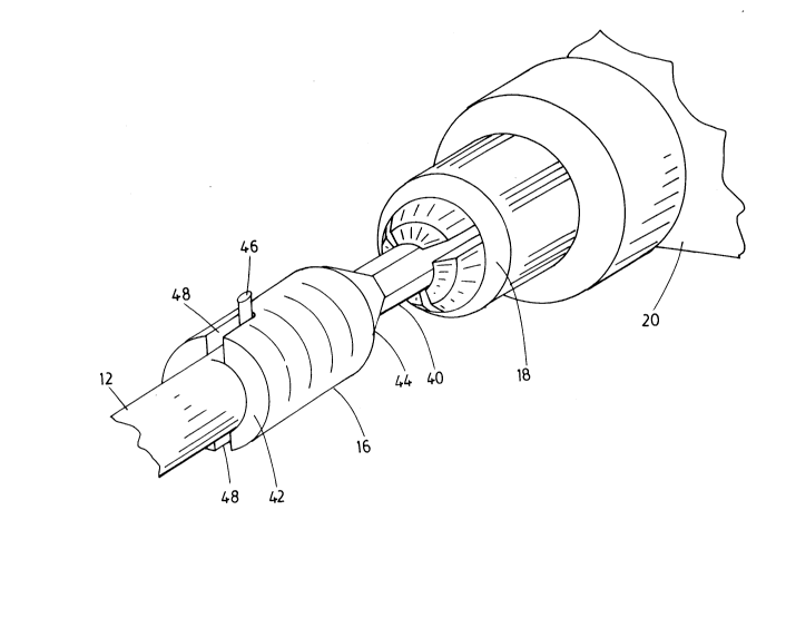
Adaptor 16 comprises a drill end 40 and a socket end
42. The drill end 40 is adapted for insertion in chuck 18
of drill 20 and conveniently may comprise a prong of
polygonal, e.g. hexagonal section, for effective gripping by
chuck 18. Thus when the prong is of hexagonal section, flat
surfaces may be presented to the chuck to obtain a positive
grip.
The drill end 40 merges into socket end 42 through a
tapered portion 44. It should be noted, however, that the
shape of the portion between ends 40, 42 is not important.
The ends may be joined by any means which is convenient and
inexpensive in manufacture.
The socket end 42 is of a dimension that the socket
will accept the end of drive shaft 12 from which handle 14
has been removed. Suitably the socket end 42 is provided
with means to engage any engagement means on the drive shaft
12 which had been provided for holding the handle 14 against
relative rotation with respect to the shaft. For example,
as shown, drive shaft 12 may be provided with diametrically
extending lugs 46 intended to engage slots on a handle
engaging part. It is very suitable to provide the socket
end 42 with slots 48 to engage lugs 46 to prevent the socket
slipping over the driveshaft 12 when drill 20 is powered up.
Figures 4 and 5 show a honey extractor 11 having a
vertical drive shaft 13. Other parts of the extractor are
similar to those of the extractor already described with
214S2(~
.
- 5 -
reference to Figures 2 and 3 and are indicated by similar
reference numerals. Drive shaft 13, although it may have a
similar handle fitting to that described with reference to
Figures 1 and 2, is illustrated with a different fitting.
Drive shaft 13 has a splined gear wheel 35 at its top end.
Gear wheel 35 meshes with an inner toothed surface of handle
cap 37. Handle 15 extends from the cap 37.
To use a power drill to operate honey extractor 11, the
handle cap 37 is removed and socket adaptor 17 is fitted in
its place. Socket adaptor 17 is similar to socket adaptor
16 already described except that the inner surface of its
socket is provided with teeth to mesh with gear wheel 35.
While adaptor 16 and adaptor 17 have been described
with different socket fittings, a universal adaptor may be
provided with both slots 48 and an inner toothed surface so
that it may be used with either type of extractor.
Alternatively, an intermediate fitting may be provided.
In use, once the drill 20 has been connected to the
extractor through adaptor 16, 17, it is only necessary to
power up the drill to operate the extractor. If the drill is
a variable speed drill, the rotation of drive shaft 12, 13
may be started slowly and the speed increased as desired.